EP1978236B1 - Saugfilter und Treibstoffversorgungsvorrichtung - Google Patents
Saugfilter und Treibstoffversorgungsvorrichtung Download PDFInfo
- Publication number
- EP1978236B1 EP1978236B1 EP08006020A EP08006020A EP1978236B1 EP 1978236 B1 EP1978236 B1 EP 1978236B1 EP 08006020 A EP08006020 A EP 08006020A EP 08006020 A EP08006020 A EP 08006020A EP 1978236 B1 EP1978236 B1 EP 1978236B1
- Authority
- EP
- European Patent Office
- Prior art keywords
- fuel
- filtration
- suction filter
- fuel pump
- connection
- Prior art date
- Legal status (The legal status is an assumption and is not a legal conclusion. Google has not performed a legal analysis and makes no representation as to the accuracy of the status listed.)
- Ceased
Links
- 239000000446 fuel Substances 0.000 title claims description 241
- 238000001914 filtration Methods 0.000 claims description 105
- 230000002093 peripheral effect Effects 0.000 claims description 40
- 239000002828 fuel tank Substances 0.000 description 17
- 230000007423 decrease Effects 0.000 description 7
- 230000003247 decreasing effect Effects 0.000 description 3
- 230000000694 effects Effects 0.000 description 3
- 239000000463 material Substances 0.000 description 3
- 239000011347 resin Substances 0.000 description 3
- 229920005989 resin Polymers 0.000 description 3
- 239000004020 conductor Substances 0.000 description 2
- 230000001105 regulatory effect Effects 0.000 description 2
- 238000005452 bending Methods 0.000 description 1
- 230000003111 delayed effect Effects 0.000 description 1
- 238000005516 engineering process Methods 0.000 description 1
- 238000004519 manufacturing process Methods 0.000 description 1
- 238000007789 sealing Methods 0.000 description 1
Images


Classifications
-
- F—MECHANICAL ENGINEERING; LIGHTING; HEATING; WEAPONS; BLASTING
- F02—COMBUSTION ENGINES; HOT-GAS OR COMBUSTION-PRODUCT ENGINE PLANTS
- F02M—SUPPLYING COMBUSTION ENGINES IN GENERAL WITH COMBUSTIBLE MIXTURES OR CONSTITUENTS THEREOF
- F02M37/00—Apparatus or systems for feeding liquid fuel from storage containers to carburettors or fuel-injection apparatus; Arrangements for purifying liquid fuel specially adapted for, or arranged on, internal-combustion engines
- F02M37/04—Feeding by means of driven pumps
- F02M37/08—Feeding by means of driven pumps electrically driven
- F02M37/10—Feeding by means of driven pumps electrically driven submerged in fuel, e.g. in reservoir
- F02M37/106—Feeding by means of driven pumps electrically driven submerged in fuel, e.g. in reservoir the pump being installed in a sub-tank
-
- F—MECHANICAL ENGINEERING; LIGHTING; HEATING; WEAPONS; BLASTING
- F02—COMBUSTION ENGINES; HOT-GAS OR COMBUSTION-PRODUCT ENGINE PLANTS
- F02M—SUPPLYING COMBUSTION ENGINES IN GENERAL WITH COMBUSTIBLE MIXTURES OR CONSTITUENTS THEREOF
- F02M37/00—Apparatus or systems for feeding liquid fuel from storage containers to carburettors or fuel-injection apparatus; Arrangements for purifying liquid fuel specially adapted for, or arranged on, internal-combustion engines
- F02M37/04—Feeding by means of driven pumps
- F02M37/14—Feeding by means of driven pumps the pumps being combined with other apparatus
-
- F—MECHANICAL ENGINEERING; LIGHTING; HEATING; WEAPONS; BLASTING
- F02—COMBUSTION ENGINES; HOT-GAS OR COMBUSTION-PRODUCT ENGINE PLANTS
- F02M—SUPPLYING COMBUSTION ENGINES IN GENERAL WITH COMBUSTIBLE MIXTURES OR CONSTITUENTS THEREOF
- F02M37/00—Apparatus or systems for feeding liquid fuel from storage containers to carburettors or fuel-injection apparatus; Arrangements for purifying liquid fuel specially adapted for, or arranged on, internal-combustion engines
- F02M37/22—Arrangements for purifying liquid fuel specially adapted for, or arranged on, internal-combustion engines, e.g. arrangements in the feeding system
- F02M37/32—Arrangements for purifying liquid fuel specially adapted for, or arranged on, internal-combustion engines, e.g. arrangements in the feeding system characterised by filters or filter arrangements
- F02M37/34—Arrangements for purifying liquid fuel specially adapted for, or arranged on, internal-combustion engines, e.g. arrangements in the feeding system characterised by filters or filter arrangements by the filter structure, e.g. honeycomb, mesh or fibrous
-
- F—MECHANICAL ENGINEERING; LIGHTING; HEATING; WEAPONS; BLASTING
- F02—COMBUSTION ENGINES; HOT-GAS OR COMBUSTION-PRODUCT ENGINE PLANTS
- F02M—SUPPLYING COMBUSTION ENGINES IN GENERAL WITH COMBUSTIBLE MIXTURES OR CONSTITUENTS THEREOF
- F02M37/00—Apparatus or systems for feeding liquid fuel from storage containers to carburettors or fuel-injection apparatus; Arrangements for purifying liquid fuel specially adapted for, or arranged on, internal-combustion engines
- F02M37/22—Arrangements for purifying liquid fuel specially adapted for, or arranged on, internal-combustion engines, e.g. arrangements in the feeding system
- F02M37/32—Arrangements for purifying liquid fuel specially adapted for, or arranged on, internal-combustion engines, e.g. arrangements in the feeding system characterised by filters or filter arrangements
- F02M37/44—Filters structurally associated with pumps
-
- F—MECHANICAL ENGINEERING; LIGHTING; HEATING; WEAPONS; BLASTING
- F02—COMBUSTION ENGINES; HOT-GAS OR COMBUSTION-PRODUCT ENGINE PLANTS
- F02M—SUPPLYING COMBUSTION ENGINES IN GENERAL WITH COMBUSTIBLE MIXTURES OR CONSTITUENTS THEREOF
- F02M37/00—Apparatus or systems for feeding liquid fuel from storage containers to carburettors or fuel-injection apparatus; Arrangements for purifying liquid fuel specially adapted for, or arranged on, internal-combustion engines
- F02M37/22—Arrangements for purifying liquid fuel specially adapted for, or arranged on, internal-combustion engines, e.g. arrangements in the feeding system
- F02M37/32—Arrangements for purifying liquid fuel specially adapted for, or arranged on, internal-combustion engines, e.g. arrangements in the feeding system characterised by filters or filter arrangements
- F02M37/50—Filters arranged in or on fuel tanks
Definitions
- the present invention relates to a fuel supply device for supplying fuel within a fuel tank to the outside of the fuel tank.
- the present invention relates to a suction filter connected to an intake port of a fuel pump.
- This type of fuel supply device comprises a fuel pump and a suction filter connected to the intake port of the fuel pump.
- the suction filter is a member for removing foreign matter contained in the fuel.
- foreign matter adheres to the surface of the suction filter over time, and the filtration resistance gradually increases. This increase in the filtration resistance leads to a decline in fuel pump efficiency
- Japanese Laid-open Patent Publication No. 2006-144553 discloses a fuel supply device.
- This fuel supply device has a connection pipe that communicates an inner space of a suction filter and a fuel intake port of a fuel pump.
- This connection pipe is bent so that the suction filter is disposed along the longitudinal direction of the fuel pump.
- the increase in the device size is avoided, while increasing the filtration surface area of the suction filter, by disposing the suction filter in the longitudinal direction of the fuel pump.
- the filtration area of the fuel filter has not been large enough, and it has not been possible to delay the increase in filtration resistance of the suction filter adequately.
- a suction filter may comprise a filtration member and a connection member.
- the filtration member has an inner space.
- the filtration member has a first filtration surface and a second filtration surface. The first filtration surface and second filtration surface are partially connected, the peripheral edges thereof are bonded together. As a result, an inner space is provided between the first filtration surface and the second filtration surface.
- the connection member is configured to communicate the inner space of the filtration member and a fuel intake port of a fuel pump.
- the connection member may have a first connection portion configured to be connected to the fuel intake port of the fuel pump. The foreign matter contained in the fuel can be removed when the fuel flows from the outside of the filtration member to the inner space of the filtration member.
- the removed foreign matter is accumulated in the surface of the filtration member.
- the fuel from which the foreign matter has been removed passes through the inner space and flows to the fuel intake port of the fuel pump via the connection member.
- the filtration member has a tubular shape so that the filtration member surrounds a circumference of the fuel pump when the first connection portion of the connection member is connected to the fuel intake port of the fuel pump. In this suction filter, since the filtration member surrounds the circumference of the fuel pump when the suction filter is connected to the fuel pump, it is possible to increase the filtration surface area of the filtration member, while suppressing the increase in the device size.
- the "tubular-shaped filtration member” may include not only members that are provided with a tubular shape by curving or bending a sheet-like filtration member, but also other various forms.
- a filtration member may comprise a plurality of sheet-like filtration portions. Each filtration portion may have an inner space. This filtration portions may be disposed side by side in the circumferential direction with respect to an axial line of the fuel pump. Further, each filtration portion may be curved or bent in the circumferential direction with respect to the axial line of the fuel pump. Furthermore, the filtration portions may be also disposed with a certain spacing in the circumferential direction (i.e., a slit (or notch) may be provided in the circumferential direction of the tubular filtration member).
- a slit is formed in the circumferential direction of the tubular-shaped filtration member
- other functional components e.g., a jet pump
- the resultant configuration can be adapted to fuel supply devices of various types.
- connection member may be connected to the filtration member in at least one location in a circumferential direction of the tubular-shaped filtration member.
- connection member may be connected to the filtration member along the entire circumference of the filtration member.
- the connection member may comprise a first sheet portion and a second sheet portion. Each of peripheral edges of the first sheet portion and the second sheet portion may be connected to the tubular-shaped filtration member. A fuel flow path may be provided between the first sheet portion and second sheet portion. One of the first sheet portion and second sheet portion may have the first connection portion.
- connection member may further have a second connection portion connected to the filtration member, and the second connection portion may have a shape gradually expanding toward the filtration member (i.e., a shape such that the cross section area of the fuel flow path increases gradually toward the filtration member).
- a flow of fuel inside the connection member is not taken into account.
- a turbulence occurs in the flow of fuel inside the connection member. Where such turbulence occurs in the fuel flow, vapor appears in the fuel or pressure loss occurs and a load is applied to the fuel pump. As a result, the fuel pump efficiency is decreased.
- the second connection portion has a shape gradually expanding toward the filtration member, the fuel that passed through the filtration member can smoothly flow into the connection member. Therefore, the flow disturbance in the fuel can be inhibited and the occurrence of vapor or pressure loss in the second connection portion can be reduced. As a result, the load applied to the fuel pump can be reduced and pump efficiency can be increased.
- connection member may be formed from a resin material. Further, it is preferred that the connection member has a certain rigidity. Furthermore, it is preferred that an inner surface (i.e., an inner wall surface of the fuel flow path) of the connection member is formed as a smooth surface. As a result, flow disturbance in the fuel can be further inhibited and the load applied to the fuel pump can be further reduced.
- the filtration surface area of the filtration member is preferably larger than a cross section area (i.e., cross section area of the fuel flow path) of the second connection portion of the connection member. Where the filtration surface area of the filtration member is increased, clogging of the suction filter can be greatly delayed. As a result, the decrease in fuel pump efficiency can be prevented.
- the above-described suction filters may be connected to the fuel pump, thereby making it possible to configure a fuel supply devices.
- the filtration member is preferably arranged with respect to the fuel pump so that the axial direction of the tubular-shaped filtration member coincides with the longitudinal direction of the fuel pump and the circumference (i.e., outer surface) of the fuel pump is surrounded by the tubular filtration member.
- the above-described fuel supply devices may be disposed within a reservoir cup.
- the fuel supply device is so disposed inside the reservoir cup that a gap is formed in at least one location in the circumferential direction between the inner wall of the reservoir cup and the outer peripheral surface of the filtration member. This is because where the inner wall of the reservoir cup and the outer peripheral surface of the filtration member are in tight contact with one another, the outer peripheral surface of the filtration member does not function as a filtration portion and the filtration surface area of the filtration member decreases.
- the reservoir cup may have a protrusion (e.g., a rib) on the inner wall of the bottom surface thereof. This protrusion may be in contact with the connection member.
- the suction filter can be supported by the protrusion at the bottom surface of the reservoir cup in a state such that the lower end of the filtration member floats above the bottom surface of the reservoir cup. Therefore, the filtration member can be prevented from being pressed against the bottom surface of the reservoir cup and deformed. By preventing the deformation of the filtration member, it is possible to prevent the decrease in the filtration surface areas of the suction filter.
- connection member may have a filtration portion in part thereof.
- the filtration surface area can be further increased and the decrease in fuel pump efficiency can be prevented more efficiently.
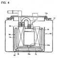
- FIG. 1 is a vertical sectional view of the fuel supply device of the first embodiment of the present teachings.
- the suction filter of the first representative embodiment of the present teachings will be described below with reference to the appended drawings.
- the fuel supply device of the present embodiment can be attached to a fuel tank of an automobile and used to supply fuel to an engine. As shown in FIG. 1 , the fuel supply device comprises a fuel discharge portion 14 and a fuel pump portion 16.
- the fuel discharge portion 14 is mounted on an opening 12a of a fuel tank 12 and covers the opening 12a.
- the fuel pump portion 16 is inserted from the opening 12a and disposed within the fuel tank 12.
- the fuel discharge portion 14 has a ring plate 18 and a lid member 20 that covers an opening 18a of the ring plate 18.
- a fuel discharge port 26 and a connector 28 are formed on the upper surface of the lid member 20.
- the fuel discharge port 26 is connected to one end of a fuel supply pipe (not shown in the figure).
- the other end of the fuel supply pipe is connected to the engine.
- the connector 28 is connected via a conductor wire (not shown in the figure) to an external power source.
- a connection section 20a that has an almost cylindrical shape extending vertically is formed on the lower surface of the lid member 20.
- a sealing member 22 is disposed between the lower surface of the peripheral edge of the lid member 20 and the upper surface of the fuel tank 12.
- a fixing member 24 that fixes the ring plate 18 to the fuel tank 12 is disposed between the lower surface of the outer peripheral edge of the ring plate 18 and the upper surface of the fuel tank 12.
- the lid member 20 is disposed so as to cover the opening 12a of the fuel tank 12, and the ring plate 18 is disposed so that the inner peripheral edge thereof is pressed against the peripheral edge of the lid member 20. With such a configuration, the fuel supply device is liquid-tightly fixed to the fuel tank 12.
- the fuel pump portion 16 comprises a housing 32, a fuel pump 34, a fuel filter 36, and a suction filter 38.
- the casing 32 has a substantially cylindrical shape that is open at the upper end and accommodates inside thereof the well-known fuel pump 34 and fuel filter 36.
- the connection section 20a of the lid member 20 is mated with the upper end of the casing 32.
- the fuel pump 34 is accommodated inside the casing 32 so that the axial line thereof is perpendicular to the opening of the fuel tank 12 and also so that a discharge port 34a is on the upper side and an intake port 34b is on the lower side.
- the discharge port 34a is connected to the fuel filter 36 via a connection pipe 40.
- the fuel filter 36 is connected to the fuel discharge port 26 via a connection pipe 30.
- a pressure regulator (not shown in the figure) is provided in the connection pipe 30.
- a connector 42 is formed at the upper end of the fuel pump 34. The connector 42 is connected to the connector 28 via a conductor wire 45.
- the suction filter 38 has a resin frame (not shown in the figure) and a bag-shaped mesh 44 covering the frame.
- the frame has a substantially cylindrical shape, and the mesh 44 is held by the frame so as to assume a substantially cylindrical shape as a whole (as shown in FIG. 1 to FIG. 3 ).
- An outer peripheral surface 45a and an inner peripheral surface 45b of the mesh 44 are connected at the upper and lower ends thereof, and an inner space 45c is formed between the outer peripheral surface 45a and the inner peripheral surface 45b (see FIG. 2 ).
- the suction filter also has a fuel channel member 46.
- the fuel channel member 46 is connected to one end (i.e., close to the lower end portion) of the substantially cylindrical-shaped mesh 44.
- the fuel channel member 46 comprises two disk-shaped sheets (i.e., upper sheet and lower sheet).
- a fuel flow path 47 is formed between the two sheets of the fuel channel member 46.
- the fuel channel member 46 is made from a resin material and has a certain rigidity. Further, the opposite surfaces of the two sheets are formed to be smooth (i.e., the inner wall surface of the fuel channel member 46 is formed to be smooth).
- a connection portion 46a for connection to the fuel pump 34 is formed at the upper surface of the fuel channel member 46. The connection portion 46a is connected to the intake port 34b of the fuel pump 34.
- the fuel channel member 46 further comprises a connection portion 48 for connection to the mesh 44.
- the connection portion 48 that is connected to the inner peripheral surface 45b of the mesh 44 has a trumpet-like shape expanding toward the mesh 44-
- the peripheral edge portion of the fuel channel member 46 expands in the up-down direction, and the vertical cross section of the expansion portion has a circular arc shape.
- the outer diameter of the suction filter 38 i.e., the outer diameter of the mesh 44
- the axial direction of the suction filter 38 coincides with the longitudinal direction of the fuel pump 34, and the suction filter 38 is disposed so as to surround the outer peripheral surface and lower portion of the casing 32 (i.e., the fuel pump 34).
- a gap is formed between the inner peripheral surface 45b of the suction filter 38 and the outer peripheral surface of the casing 32.
- a gap is also formed between the outer peripheral surface 45a of the suction filter 38 and the fuel tank 12.
- the fuel pump 34 When electric power is supplied from the external power source to the fuel pump 34, the fuel pump 34 is actuated. When the fuel pump 34 is actuated, the fuel within the fuel tank 12 is sucked from the outside (i.e., outer peripheral surface 45a and inner peripheral surface 45b) of the mesh 44 of the suction filter 38 to the inside (i.e., the inner space 45c)- At this time, the fuel is filtered by the mesh 44, and foreign matter contained in the fuel adheres to the outer surface (i.e., outer peripheral surface 45a and inner peripheral surface 45b) of the mesh 44. The fuel from which the foreign matter has been removed flows from the inner space 45c of the mesh 44 into the fuel channel member 46.
- the fuel flowing through the fuel channel member 46 is taken from the intake port 34b into the fuel pump 34.
- the fuel taken into the fuel pump 34 is pressurized and discharged from the discharge port 34a.
- the fuel discharged from the discharge port 34a is sent to the fuel filter 36 and filtered again.
- the pressure of the fuel discharged from the fuel filter 36 is regulated by the pressure regulator to a pressure corresponding to the operation state of the engine.
- the fuel with a regulated pressure is supplied from the fuel discharge port 26 to the engine.
- the mesh 44 which is a fuel filtration portion of the suction filter 38, is formed to have a cylindrical shape and extends in the up-down direction along the circumferential surface of the fuel pump 34.
- the connection portion 48 of the fuel channel member 46 has a trumpet-like shape that expands toward the mesh 44. Therefore, the fuel that passed through the mesh 44 can flow smoothly into the fuel channel member 46, and the occurrence of vapor in the connection portion 48 or pressure loss in the connection portion 48 can be inhibited. As a consequence, a load applied to the fuel pump 34 can be decreased and pump efficiency can be further increased.
- the fuel tank 12 has a reservoir cup 62 disposed in the bottom portion of the fuel tank 12.
- the fuel pump portion 66 is disposed within the reservoir cup 62.
- the fuel pump portion 66 comprises a fuel pump 34, a fuel filter 36, and a suction filter 68.
- the fuel filter 36 has a substantially cylindrical shape and is disposed around the fuel pump 34.
- the suction filter 68 is configured in the same manner as in the first embodiment.
- the suction filter 68 has a mesh 74 of a substantially cylindrical shape and a disk-shaped fuel channel member 76 connected to the lower portion of the mesh 74.
- a connection portion 78 of the fuel channel member 76 has a trumpet-like shape similar to that of the first embodiment.
- a connection portion 76a is formed at the upper surface of the fuel channel member 76.
- the connection portion 76a is connected to an intake port 34b of the fuel pump 34.
- the suction filter 68 is disposed so as to surround the outer peripheral surface and lower portion of the fuel filter 36.
- the reservoir cup 62 has a substantially cylindrical shape, and the upper end thereof is open and has a bottom portion.
- the reservoir cup 62 accommodates the fuel pump 34, fuel filter 36, and suction filter 68.
- a gap is formed between the outer peripheral surface of the suction filter 68 and the inner peripheral surface of the reservoir cup 62.
- the outer diameter of the reservoir cup 62 is somewhat less than the diameter of an opening 12a of the fuel tank 12.
- the suction filter 68 is disposed between the fuel filter 36 surrounding the periphery of the fuel pump 34 and the reservoir cup 62.
- the mesh 74 which is a fuel filtration portion of the suction filter 68, extends in the up-down direction along the circumferential surface of the fuel pump 34 and is disposed so as to overlap the fuel pump 34 in the axial direction. Therefore, in the fuel supply device of the present embodiment, the filtration surface area can be increased, without increasing the size of the apparatus.
- the connection portion 78 of the fuel channel member 76 has a trumpet-like shape, as in the first embodiment, and the pressure loss of fuel in the connection portion 78 can be reduced. As a result, the load applied to the fuel pump 34 can be decreased and the efficiency of fuel pump 34 can be increased.
- a notch (or slit) is formed in part of a mesh 84 held to have a cylindrical shape (thus, the horizontal cross section of the mesh 84 has a circular arc shape).
- a disk-shaped fuel channel member 86 is disposed in the lower portion of the mesh 84.
- An outer end portion of the fuel channel member 86 is connected to the mesh 84 and closed in a portion where the notch is formed in the mesh 84.
- the connection portion of the fuel channel member 86 has a trumpet-like shape similar to that in the first embodiment.
- a connection portion 86a for connecting to an intake port 34b of the fuel pump 34 is formed at the upper surface of the fuel channel member 86.
- a notch is provided in the mesh 84 of the suction filter 82.
- the mesh 84 can be easily formed to have a bag-like shape and the productivity can be greatly increased.
- other functional components e.g., a jet pump
- the suction filter can be adapted to devices of various configurations.
- the shape of a suction filter 92 is different from that of suction filter of the third embodiment.
- notches are formed in two locations in the circumferential direction of a mesh 94 (the mesh 94 is split into two sections by the notches (i.e., the mesh 94 has two filtration portions)).
- the two notches are formed in opposing locations.
- the two notches of the mesh 94 are disposed in the opposing locations, but the position of the notches can be changed appropriately (e.g., they can be changed appropriately according to the arrangement of other functional components (a jet pump)).
- a disk-shaped fuel channel member 96 is provided in the lower part of the mesh 94.
- the outer end portion of the fuel channel member 96 is connected to the mesh 94 and is closed by a portion where the notch is formed in the mesh 94.
- the connection portion of the fuel channel member 96 has a trumpet-like shape similar to that of the first embodiment-
- a connection portion 96a for connection to an intake port 34b of the fuel pump 34 is formed at the upper surface of the fuel channel member 96.
- the suction filter 92 of the present embodiment can be used as a suction filter of the fuel supply devices of the above-described other embodiments.
- the shape of a fuel channel 106 of a suction filter 102 is different from that of suction filters of the first embodiment or second embodiment.
- two tubular fuel channel members 106 are connected in the lower part of a mesh 104.
- the fuel channel members 106 intersect in the center of the mesh 104. Both ends of each fuel channel member 106 are connected to the mesh 104, and each connection portion is formed to have a trumpet-like shape, similarly to the first embodiment.
- a connection portion 106a for connection to an intake port 34b of the fuel pump 34 is formed in a portion where the fuel channel members 106 intersect.
- the effect obtained with the suction filter 102 of the present embodiment is substantially identical to that obtained in the first embodiment or second embodiment. Further, because the mesh 104 is supported by the two fuel channel members 106 in four locations in the circumferential directions, the cylindrical shape of the mesh 104 can be advantageously maintained.
- the number of fuel channels that communicate the mesh and the fuel pump is not limited to 2 and may be 1 or 3 and more.
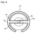
- a fuel channel 116 of a suction filter 112 is different from that of the suction filter of the third embodiment.
- a notch is formed in part in the circumferential direction of a mesh 114.
- One tubular fuel channel member 116 is disposed in the lower portion of the mesh 114. Both ends of the fuel channel member 116 are connected to the mesh 114, and the connection portions are formed to have a trumpet-like shape.
- the fuel channel member 116 passes through the center of the mesh 114, and a connection portion 116a for connection to an intake port 34b of the fuel pump 34 is formed in the central portion.
- a plurality of fuel channel members may be also provided in the fuel supply device of the present embodiment.
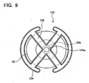
- a fuel channel member 126 of a suction filter 122 is partially different from that of the suction filter of the fourth embodiment.
- notches are formed in two location in the circumferential direction of a mesh 124.
- Two tubular fuel channel members 126 are disposed in the lower portion of the mesh 124. Both ends of each fuel channel member 126 are connected to the mesh 124, and the connection portions thereof are formed to have a trumpet-like shape.
- the fuel channel members 126 intersect in the center of the mesh 124.
- a connection portion 126a for connection to an intake port 34b of the fuel pump 34 is formed in the central portion.
- the effect obtained with the present embodiment is substantially identical to that obtained with the fourth embodiment.
- the number of fuel channel members 126 in the present embodiment also may be 1, or 3 or more.
- the shape of a reservoir cup 138 is different from that of the second embodiment.
- the reservoir cup 138 accommodates a fuel pump 34, a fuel filter 36, and a suction filter 132.
- Eight ribs 138a extending in the up-down direction i.e., axial line direction of the fuel pump 34
- the ribs 138a protrude toward the center so as come into contact with the outer peripheral surface of the suction filter 132.
- a gap equal to the protrusion length of the ribs 138a is formed between the outer peripheral surface of the suction filter 132 and the inner peripheral surface of the reservoir cup 138.
- the ribs 138a are formed on the inner peripheral surface of the reservoir cup 138, the outer peripheral surface of the suction filter 132 and the inner peripheral surface of the reservoir cup 138 arc not contacted tightly together- As a result, the outer peripheral surface of the suction filter 132 can reliably function as a filtration portion.
- the shape, number, and positions of ribs 138a may be changed appropriately.
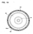
- the shape of a reservoir cup 148 is partially different from that of the second embodiment.
- the reservoir cup 148 accommodates a fuel pump 34, a fuel filter 36, and a suction filter 142.
- a rib 148a of a cylindrical shape is formed at a bottom surface of the reservoir cup 148.
- the rib 148a protrudes upward from the bottom surface of the reservoir cup 148 and supports the lower surface of a fuel channel member 146 of the suction filter 142.
- the suction filter 142 is supported by the rib 148a in a state such that the lower end of the filter (i.e., lower end of the mesh 144) floats above the bottom surface of the reservoir cup 148.
- the suction filter 142 is supported by the rib 148a, which is formed at the bottom surface of the reservoir cup 148, in a state such that the lower end of the mesh 144 floats above the bottom surface of the reservoir cup 148.
- the lower end of the mesh 144 is not pressed against the bottom surface of the reservoir cup 148. Therefore, the decrease in the filtration surface areas of the suction filter 142 caused by the deformation of the mesh 144 can be prevented.
- the shape, number and position of the rib 148a may be changed appropriately.
- the configuration of a fuel channel member 156 is partially different from that of the ninth embodiment.
- mesh portions 156a, 156b are provided concentrically with the fuel channel member 156.
- the mesh portion 156a is formed at the upper surface of the fuel channel member 156.
- the mesh portion 156b is formed at the lower surface of the fuel channel member 156.
- the mesh portions 156a, 156b are made from the same material as the mesh 154 of the suction filter 152.
- a rib 148a formed at the bottom surface of a reservoir cup 148 supports a portion (this portion has a certain rigidity) of the lower surface of the fuel channel member 156 outside the mesh portion 156b.
- the suction filter 152 is supported by the rib 148a so that the lower end of the mesh 154 is lifted above the bottom surface of the reservoir cup 148.
- the fuel filtration portion is provided not only around the fuel pump 34, but also below it.
- the filtration surface area is increased and, therefore, the decrease in pump efficiency can be effectively inhibited.
- the fuel channel member 156 can be easily deformed by installing the mesh portions 156a, 156b, it is possible to attenuate or absorb vibrations occurring when the fuel pump 34 is driven. Further, the shape and location of the mesh portions 156a, 156b provided in the fuel channel member 156 may be changed appropriately.
Landscapes
- Engineering & Computer Science (AREA)
- Chemical & Material Sciences (AREA)
- Combustion & Propulsion (AREA)
- Mechanical Engineering (AREA)
- General Engineering & Computer Science (AREA)
- Filtration Of Liquid (AREA)
- Cooling, Air Intake And Gas Exhaust, And Fuel Tank Arrangements In Propulsion Units (AREA)
- Details Of Reciprocating Pumps (AREA)
- Reciprocating Pumps (AREA)
Claims (9)
- Ansaugfilter (38) mit
einem Filtrierelement (44), das einen Innenraum (45c) aufweist, und
einem Verbindungselement (46), das zum Verbinden des Innenraums (45c) des Filtrierelements (44) und einer Kraftstoffeinlassöffnung (34b) einer Kraftstoffpumpe (34) ausgebildet ist, wobei das Verbindungselement (46) einen ersten Verbindungsbereich (46a) aufweist, der dazu ausgebildet ist, mit der Kraftstoffeinlassöffnung (34b) der Kraftstoffpumpe (34) verbunden zu werden,
wobei das Filtrierelement (44) eine röhrenförmige Form aufweist, so dass das Filtrierelement (44) einen Umfang der Kraftstoffpumpe (34) umgibt, wenn der erste Verbindungsbereich (46a) des Verbindungselements (46) mit der Kraftstoffeinlassöffnung (34b) der Kraftstoffpumpe (34) verbunden ist,
dadurch gekennzeichnet, dass
das Filtrierelement (44) eine erste Filtrieroberfläche (45a) und eine zweite Filtrieroberfläche (45b) aufweist, eine Umfangskante der ersten Filtrieroberfläche (45a) und eine Umfangskante der zweiten Filtrieroberfläche (45b) zum Schaffen des Innenraums (45c) zwischen der ersten Filtrieroberfläche (45a) und der zweiten Filtrieroberfläche (45b) miteinander verbunden sind, und sowohl die erste als auch die zweite Oberfläche (45a, 45b) zum Entfernen von Fremdstoffen, die in Kraftstoff enthalten sind, angepasst sind,. - Ansaugfilter nach Anspruch 1, bei dem das Filtrierelement (44) eine Mehrzahl von Filtrierbereichen aufweist, jeder der Filtrierbereiche einen Innenraum aufweist und die Filtrierbereiche Seite an Seite in der Umfangsrichtung bezüglich einer Axiallinie des Filtrierelements (44) angeordnet sind.
- Ansaugfilter nach Anspruch 2, bei dem die Filtrierbereiche mit einem bestimmten Abstand in der Umfangsrichtung angeordnet sind.
- Ansaugfilter nach einem der Ansprüche 1 bis 3, bei dem das Verbindungselement einen zweiten Verbindungsbereich, der mit dem röhrenförmigen Filtrierelement verbunden ist, aufweist und der zweite Verbindungsbereich eine Form aufweist, die sich graduell in Richtung des Filtrierelements (44) aufweitet.
- Ansaugfilter nach einem der Ansprüche 1 bis 4, bei dem das Verbindungselement (46) einen ersten Plattenbereich und einen zweiten Plattenbereich aufweist, jede der Umfangskanten des ersten Plattenbereichs und des zweiten Plattenbereichs mit dem Filtrierelement (44) verbunden sind, und ein Kraftstoffströmungspfad zwischen dem ersten Plattenbereich und dem zweiten Plattenbereich vorgesehen ist.
- Kraftstoffzufiihrvorrichtung, mit
einer Kraftstoffpumpe (34), und
einem Ansaugfilter (38) nach einem der Ansprüche 1 bis 5, wobei der Ansaugfilter (38) mit der Kraftstoffpumpe (34) verbunden ist,
bei der das Filtrierelement (44) bezüglich der Kraftstoffpumpe (34) derart angeordnet ist, dass eine Axialrichtung des röhrenförmigen Filtrierelements (44) mit einer Längsrichtung der Kraftstoffpumpe (34) übereinstimmt und ein Umfang der Kraftstoffpumpe (34) von dem schlauchförmigen Filtrierelement (44) umgeben ist. - Vorrichtung, mit:einem Reservoir, undeiner Kraftstoffzufiihrvorrichtung nach Anspruch 6, wobei die Kraftstoffzuführvorrichtung in dem Reservoir angeordnet ist,bei der ein Spalt an mindestens einem Ort in der Umfangsrichtung zwischen der Innenwand des Reservoirs und der Außenumfangsoberfläche des Filtrierelements (44) vorgesehen ist.
- Vorrichtung nach Anspruch 7, bei der das Reservoir einen Vorsprung auf einer Innenwand einer Bodenoberfläche aufweist und der Vorsprung in Kontakt mit dem Verbindungselement (46) ist.
- Vorrichtung nach Anspruch 7 oder 8, bei der das Verbindungselement (46) einen Filtrierbereich aufweist.
Applications Claiming Priority (1)
| Application Number | Priority Date | Filing Date | Title |
|---|---|---|---|
| JP2007100153A JP4804404B2 (ja) | 2007-04-06 | 2007-04-06 | 燃料ポンプ装置及び燃料供給装置 |
Publications (3)
| Publication Number | Publication Date |
|---|---|
| EP1978236A2 EP1978236A2 (de) | 2008-10-08 |
| EP1978236A3 EP1978236A3 (de) | 2010-01-06 |
| EP1978236B1 true EP1978236B1 (de) | 2012-06-27 |
Family
ID=39645434
Family Applications (1)
| Application Number | Title | Priority Date | Filing Date |
|---|---|---|---|
| EP08006020A Ceased EP1978236B1 (de) | 2007-04-06 | 2008-03-28 | Saugfilter und Treibstoffversorgungsvorrichtung |
Country Status (3)
| Country | Link |
|---|---|
| US (1) | US7857143B2 (de) |
| EP (1) | EP1978236B1 (de) |
| JP (1) | JP4804404B2 (de) |
Families Citing this family (16)
| Publication number | Priority date | Publication date | Assignee | Title |
|---|---|---|---|---|
| JP2010101306A (ja) * | 2008-09-24 | 2010-05-06 | Yamashin-Filter Corp | 液供給装置、燃料供給装置 |
| JP5571366B2 (ja) | 2009-12-04 | 2014-08-13 | 愛三工業株式会社 | フィルタ装置 |
| JP4960470B2 (ja) * | 2010-04-07 | 2012-06-27 | 三菱電機株式会社 | 燃料供給装置および燃料供給システム |
| DE102010014314A1 (de) * | 2010-04-09 | 2011-10-13 | Emitec Gesellschaft Für Emissionstechnologie Mbh | Vorrichtung zur Bereitstellung von flüssigem Reduktionsmittel |
| DE102010042196A1 (de) * | 2010-10-08 | 2012-04-12 | Robert Bosch Gmbh | Kraftstoff-Fördereinrichtung mit topfförmigem Vorfilter |
| KR101005096B1 (ko) * | 2010-10-25 | 2010-12-30 | 주식회사 코아비스 | 진동 감쇄를 위한 연료펌프 모듈 |
| US8372278B1 (en) * | 2012-03-21 | 2013-02-12 | GM Global Technology Operations LLC | Liquid fuel strainer assembly |
| KR101340914B1 (ko) * | 2013-05-23 | 2013-12-13 | 주식회사 코아비스 | 스트레이너 및 이를 포함하는 연료펌프모듈 |
| JP5992366B2 (ja) * | 2013-06-11 | 2016-09-14 | 愛三工業株式会社 | 燃料供給装置 |
| JP6382700B2 (ja) * | 2014-12-02 | 2018-08-29 | 株式会社ケーヒン | 燃料供給装置 |
| JP6459773B2 (ja) * | 2015-05-21 | 2019-01-30 | 株式会社デンソー | サクションフィルタ及び燃料供給装置 |
| JP6380364B2 (ja) * | 2015-12-17 | 2018-08-29 | 株式会社デンソー | 燃料ポンプ及び燃料ポンプモジュール |
| JP2018178953A (ja) * | 2017-04-20 | 2018-11-15 | 愛三工業株式会社 | 燃料供給装置 |
| US10731613B2 (en) * | 2017-10-06 | 2020-08-04 | Kohler Co. | System and method for supporting an in-tank fuel pump |
| JP2020016158A (ja) * | 2018-07-23 | 2020-01-30 | 京三電機株式会社 | 燃料供給装置 |
| KR102178858B1 (ko) * | 2019-09-25 | 2020-11-13 | 주식회사 코아비스 | 연료펌프용 스트레이너 |
Family Cites Families (22)
| Publication number | Priority date | Publication date | Assignee | Title |
|---|---|---|---|---|
| US1601503A (en) * | 1926-06-04 | 1926-09-28 | Walter T Munro | Filter for gasoline and the like |
| US4304664A (en) * | 1980-05-05 | 1981-12-08 | General Motors Corporation | Fuel strainer assembly |
| US5511957A (en) * | 1994-09-27 | 1996-04-30 | Walbro Corporation | High capacity fuel pump and filter combination |
| DE19619992A1 (de) * | 1996-05-17 | 1997-11-20 | Bosch Gmbh Robert | Kraftstoff-Fördermodul mit integriertem Kraftstoff-Feinfilter |
| US5860796A (en) * | 1996-08-07 | 1999-01-19 | Parker-Hannifin Corporation | Fuel pump assembly and filter element therefor |
| DE19709781A1 (de) * | 1997-03-10 | 1998-09-17 | Bosch Gmbh Robert | Abscheider |
| JP3566305B2 (ja) * | 1997-03-11 | 2004-09-15 | 愛三工業株式会社 | 帯電しにくいように改善されたインタンク式燃料フィルタ |
| US5876599A (en) * | 1997-04-07 | 1999-03-02 | Kuss Corporation | Compact in-tank fuel filter and module |
| FR2798164B1 (fr) * | 1999-09-07 | 2001-11-23 | Marwal Systems | Dispositif de puisage de carburant pour reservoir de vehicule automobile |
| JP2001082274A (ja) * | 1999-09-16 | 2001-03-27 | Keihin Corp | 燃料供給装置 |
| US6555000B2 (en) * | 1999-12-03 | 2003-04-29 | Parker-Hannifin Corporation | Fuel filter with bypass valve |
| DE10118050B4 (de) * | 2001-04-11 | 2004-11-18 | Siemens Ag | Feinfilter für eine Kraftstofffördereinheit |
| US6746603B2 (en) * | 2001-06-08 | 2004-06-08 | Federal-Mogul World Wide, Inc. | Fuel filtering system with valve |
| JP2003193929A (ja) * | 2001-10-16 | 2003-07-09 | Denso Corp | 燃料フィルタの製造方法 |
| US6887388B2 (en) * | 2001-12-27 | 2005-05-03 | Federal-Mogul World Wide, Inc. | Fuel pump/filter integration |
| JP2003269277A (ja) * | 2002-03-15 | 2003-09-25 | Denso Corp | 燃料供給装置 |
| JP4267545B2 (ja) * | 2004-09-03 | 2009-05-27 | 愛三工業株式会社 | 燃料ポンプユニット |
| JP2006144553A (ja) | 2004-11-16 | 2006-06-08 | Keihin Corp | 燃料ポンプユニット装置 |
| JP2006194239A (ja) | 2004-12-13 | 2006-07-27 | Aisan Ind Co Ltd | 燃料供給装置 |
| JP2006226222A (ja) | 2005-02-18 | 2006-08-31 | Hitachi Ltd | 燃料ポンプモジュール |
| JP2007224748A (ja) * | 2006-02-21 | 2007-09-06 | Denso Corp | サクションフィルタおよびそれを用いた燃料供給装置 |
| US20080107549A1 (en) * | 2006-11-08 | 2008-05-08 | Ti Group Automotive Systems, L.L.C. | Fuel pump and filter assembly |
-
2007
- 2007-04-06 JP JP2007100153A patent/JP4804404B2/ja active Active
-
2008
- 2008-03-27 US US12/078,080 patent/US7857143B2/en not_active Expired - Fee Related
- 2008-03-28 EP EP08006020A patent/EP1978236B1/de not_active Ceased
Also Published As
| Publication number | Publication date |
|---|---|
| JP4804404B2 (ja) | 2011-11-02 |
| US20080245724A1 (en) | 2008-10-09 |
| EP1978236A3 (de) | 2010-01-06 |
| US7857143B2 (en) | 2010-12-28 |
| JP2008255917A (ja) | 2008-10-23 |
| EP1978236A2 (de) | 2008-10-08 |
Similar Documents
| Publication | Publication Date | Title |
|---|---|---|
| EP1978236B1 (de) | Saugfilter und Treibstoffversorgungsvorrichtung | |
| RU2749960C2 (ru) | Фильтры в сборе, их элементы и отличительные признаки, способы их применения и сборки | |
| CN101991985B (zh) | 用于过滤流体的过滤器系统的密封装置 | |
| JP4267545B2 (ja) | 燃料ポンプユニット | |
| US8114285B2 (en) | Tri-flow filter element with venting | |
| US8893686B2 (en) | Suction filter | |
| US20210003132A1 (en) | Electric pump | |
| EP2815120B1 (de) | Filtereinsatzanordnung und herstellungsverfahren dafür | |
| US7112278B2 (en) | Fuel filter having double layer structure | |
| US11351484B2 (en) | Spin-on filter for suction-side and pressure-side applications in filtration systems | |
| CN105582719A (zh) | 中空过滤器元件、过滤器、过滤器壳体以及密封件 | |
| JP4552906B2 (ja) | 燃料供給装置 | |
| CN105582758A (zh) | 过滤器、中空过滤器元件和过滤器壳体以及密封件 | |
| WO2002016754A1 (en) | Fuel feed device | |
| JP5709220B2 (ja) | 燃料供給装置 | |
| JP4194589B2 (ja) | 燃料供給装置 | |
| KR20110105340A (ko) | 필터 장치 | |
| JP4273324B2 (ja) | 燃料フィルタ | |
| KR20130004275A (ko) | 필터 장치에 필터 부재를 수용하기 위한 하우징 포트 | |
| CN107075993B (zh) | 具有内锁环的过滤器滤筒 | |
| JP2007255376A (ja) | 燃料供給装置 | |
| JP4577389B2 (ja) | 燃料供給装置 | |
| JP2009209842A (ja) | ポンプモジュール | |
| CN115461534B (zh) | 燃料供给装置 | |
| JP2007255377A (ja) | 燃料供給装置 |
Legal Events
| Date | Code | Title | Description |
|---|---|---|---|
| PUAI | Public reference made under article 153(3) epc to a published international application that has entered the european phase |
Free format text: ORIGINAL CODE: 0009012 |
|
| 17P | Request for examination filed |
Effective date: 20080328 |
|
| AK | Designated contracting states |
Kind code of ref document: A2 Designated state(s): AT BE BG CH CY CZ DE DK EE ES FI FR GB GR HR HU IE IS IT LI LT LU LV MC MT NL NO PL PT RO SE SI SK TR |
|
| AX | Request for extension of the european patent |
Extension state: AL BA MK RS |
|
| PUAL | Search report despatched |
Free format text: ORIGINAL CODE: 0009013 |
|
| AK | Designated contracting states |
Kind code of ref document: A3 Designated state(s): AT BE BG CH CY CZ DE DK EE ES FI FR GB GR HR HU IE IS IT LI LT LU LV MC MT NL NO PL PT RO SE SI SK TR |
|
| AX | Request for extension of the european patent |
Extension state: AL BA MK RS |
|
| AKX | Designation fees paid |
Designated state(s): DE FR |
|
| GRAP | Despatch of communication of intention to grant a patent |
Free format text: ORIGINAL CODE: EPIDOSNIGR1 |
|
| GRAS | Grant fee paid |
Free format text: ORIGINAL CODE: EPIDOSNIGR3 |
|
| GRAA | (expected) grant |
Free format text: ORIGINAL CODE: 0009210 |
|
| AK | Designated contracting states |
Kind code of ref document: B1 Designated state(s): DE FR |
|
| REG | Reference to a national code |
Ref country code: DE Ref legal event code: R096 Ref document number: 602008016632 Country of ref document: DE Effective date: 20120823 |
|
| PLBE | No opposition filed within time limit |
Free format text: ORIGINAL CODE: 0009261 |
|
| STAA | Information on the status of an ep patent application or granted ep patent |
Free format text: STATUS: NO OPPOSITION FILED WITHIN TIME LIMIT |
|
| 26N | No opposition filed |
Effective date: 20130328 |
|
| REG | Reference to a national code |
Ref country code: DE Ref legal event code: R097 Ref document number: 602008016632 Country of ref document: DE Effective date: 20130328 |
|
| REG | Reference to a national code |
Ref country code: FR Ref legal event code: PLFP Year of fee payment: 9 |
|
| REG | Reference to a national code |
Ref country code: FR Ref legal event code: PLFP Year of fee payment: 10 |
|
| REG | Reference to a national code |
Ref country code: FR Ref legal event code: PLFP Year of fee payment: 11 |
|
| PGFP | Annual fee paid to national office [announced via postgrant information from national office to epo] |
Ref country code: DE Payment date: 20200317 Year of fee payment: 13 |
|
| PGFP | Annual fee paid to national office [announced via postgrant information from national office to epo] |
Ref country code: FR Payment date: 20200214 Year of fee payment: 13 |
|
| REG | Reference to a national code |
Ref country code: DE Ref legal event code: R119 Ref document number: 602008016632 Country of ref document: DE |
|
| PG25 | Lapsed in a contracting state [announced via postgrant information from national office to epo] |
Ref country code: FR Free format text: LAPSE BECAUSE OF NON-PAYMENT OF DUE FEES Effective date: 20210331 Ref country code: DE Free format text: LAPSE BECAUSE OF NON-PAYMENT OF DUE FEES Effective date: 20211001 |