EP1978199B1 - Composant en verre isolant du vide et procédé et dispositif de fabrication - Google Patents
Composant en verre isolant du vide et procédé et dispositif de fabrication Download PDFInfo
- Publication number
- EP1978199B1 EP1978199B1 EP07007253.3A EP07007253A EP1978199B1 EP 1978199 B1 EP1978199 B1 EP 1978199B1 EP 07007253 A EP07007253 A EP 07007253A EP 1978199 B1 EP1978199 B1 EP 1978199B1
- Authority
- EP
- European Patent Office
- Prior art keywords
- metal foil
- glass
- vacuum
- foil strips
- building element
- Prior art date
- Legal status (The legal status is an assumption and is not a legal conclusion. Google has not performed a legal analysis and makes no representation as to the accuracy of the status listed.)
- Active
Links
Images

Classifications
-
- E—FIXED CONSTRUCTIONS
- E06—DOORS, WINDOWS, SHUTTERS, OR ROLLER BLINDS IN GENERAL; LADDERS
- E06B—FIXED OR MOVABLE CLOSURES FOR OPENINGS IN BUILDINGS, VEHICLES, FENCES OR LIKE ENCLOSURES IN GENERAL, e.g. DOORS, WINDOWS, BLINDS, GATES
- E06B3/00—Window sashes, door leaves, or like elements for closing wall or like openings; Layout of fixed or moving closures, e.g. windows in wall or like openings; Features of rigidly-mounted outer frames relating to the mounting of wing frames
- E06B3/66—Units comprising two or more parallel glass or like panes permanently secured together
- E06B3/677—Evacuating or filling the gap between the panes ; Equilibration of inside and outside pressure; Preventing condensation in the gap between the panes; Cleaning the gap between the panes
- E06B3/6775—Evacuating or filling the gap during assembly
-
- E—FIXED CONSTRUCTIONS
- E06—DOORS, WINDOWS, SHUTTERS, OR ROLLER BLINDS IN GENERAL; LADDERS
- E06B—FIXED OR MOVABLE CLOSURES FOR OPENINGS IN BUILDINGS, VEHICLES, FENCES OR LIKE ENCLOSURES IN GENERAL, e.g. DOORS, WINDOWS, BLINDS, GATES
- E06B3/00—Window sashes, door leaves, or like elements for closing wall or like openings; Layout of fixed or moving closures, e.g. windows in wall or like openings; Features of rigidly-mounted outer frames relating to the mounting of wing frames
- E06B3/66—Units comprising two or more parallel glass or like panes permanently secured together
- E06B3/6612—Evacuated glazing units
-
- E—FIXED CONSTRUCTIONS
- E06—DOORS, WINDOWS, SHUTTERS, OR ROLLER BLINDS IN GENERAL; LADDERS
- E06B—FIXED OR MOVABLE CLOSURES FOR OPENINGS IN BUILDINGS, VEHICLES, FENCES OR LIKE ENCLOSURES IN GENERAL, e.g. DOORS, WINDOWS, BLINDS, GATES
- E06B3/00—Window sashes, door leaves, or like elements for closing wall or like openings; Layout of fixed or moving closures, e.g. windows in wall or like openings; Features of rigidly-mounted outer frames relating to the mounting of wing frames
- E06B3/66—Units comprising two or more parallel glass or like panes permanently secured together
- E06B3/663—Elements for spacing panes
- E06B3/66304—Discrete spacing elements, e.g. for evacuated glazing units
-
- E—FIXED CONSTRUCTIONS
- E06—DOORS, WINDOWS, SHUTTERS, OR ROLLER BLINDS IN GENERAL; LADDERS
- E06B—FIXED OR MOVABLE CLOSURES FOR OPENINGS IN BUILDINGS, VEHICLES, FENCES OR LIKE ENCLOSURES IN GENERAL, e.g. DOORS, WINDOWS, BLINDS, GATES
- E06B3/00—Window sashes, door leaves, or like elements for closing wall or like openings; Layout of fixed or moving closures, e.g. windows in wall or like openings; Features of rigidly-mounted outer frames relating to the mounting of wing frames
- E06B3/66—Units comprising two or more parallel glass or like panes permanently secured together
- E06B3/673—Assembling the units
- E06B3/67339—Working the edges of already assembled units
- E06B3/6736—Heat treatment
-
- Y—GENERAL TAGGING OF NEW TECHNOLOGICAL DEVELOPMENTS; GENERAL TAGGING OF CROSS-SECTIONAL TECHNOLOGIES SPANNING OVER SEVERAL SECTIONS OF THE IPC; TECHNICAL SUBJECTS COVERED BY FORMER USPC CROSS-REFERENCE ART COLLECTIONS [XRACs] AND DIGESTS
- Y02—TECHNOLOGIES OR APPLICATIONS FOR MITIGATION OR ADAPTATION AGAINST CLIMATE CHANGE
- Y02A—TECHNOLOGIES FOR ADAPTATION TO CLIMATE CHANGE
- Y02A30/00—Adapting or protecting infrastructure or their operation
- Y02A30/24—Structural elements or technologies for improving thermal insulation
- Y02A30/249—Glazing, e.g. vacuum glazing
-
- Y—GENERAL TAGGING OF NEW TECHNOLOGICAL DEVELOPMENTS; GENERAL TAGGING OF CROSS-SECTIONAL TECHNOLOGIES SPANNING OVER SEVERAL SECTIONS OF THE IPC; TECHNICAL SUBJECTS COVERED BY FORMER USPC CROSS-REFERENCE ART COLLECTIONS [XRACs] AND DIGESTS
- Y02—TECHNOLOGIES OR APPLICATIONS FOR MITIGATION OR ADAPTATION AGAINST CLIMATE CHANGE
- Y02B—CLIMATE CHANGE MITIGATION TECHNOLOGIES RELATED TO BUILDINGS, e.g. HOUSING, HOUSE APPLIANCES OR RELATED END-USER APPLICATIONS
- Y02B80/00—Architectural or constructional elements improving the thermal performance of buildings
- Y02B80/22—Glazing, e.g. vaccum glazing
Definitions
- the invention relates to a vacuum insulating glass component, which term means not only a vacuum insulating glass pane, but also another component which consists of a combination of vacuum insulating glass with, for example, a solar module.
- the invention also relates to a method for producing such a vacuum insulating glass component.
- the invention therefore relates to arrangements in which at least two glass plates or other sheet-like glass structures, with or without the inclusion of another planar body, are connected together to form a thin evacuated gap.
- Vacuum insulating glass is known per se. It differs from conventional insulating glass in that the space between the panes is evacuated while it is filled with a noble gas in normal insulating glass. Also, in the case of vacuum insulating glass, the space between the panes is considerably thinner than in the case of normal insulating glass, namely only about 0.7 mm or less, because with vacuum insulating glass no convection takes place between the individual panes due to the vacuum.
- the two individual disks are supported by grid-like over the glass surface distributed supports together so that the external air pressure can not compress them, and they are connected at their edges by a vacuum-tight edge bond.
- vacuum insulating glass panes are produced by placing spacers on a first individual glass pane in the provided grid arrangement and fixing them by gluing, and then laying the second individual glass pane on top of them.
- the laid glass has a hole in the region of its edge with a sealed, namely with glass solder fixed or glued suction, to which a suction hose of a vacuum pump can be connected.
- the two glass sheets are then laser welded along their edges with glass solder under atmospheric conditions.
- the applied glass pane is a few millimeters smaller in size than the underlying disc, so that the edge of the applied disc is each set back slightly with respect to the edge of the underlying disc. This can then be done by means of a directed from above the arrangement of the laser beam, the laser welding of the two discs with glass solder.
- the space between the panes is evacuated via the suction nozzle.
- the evacuation takes about two hours or longer, while the glass composite is maintained at a temperature of about 400 ° C to about 450 ° C. Only in this way can volatiles, mainly water, that sit in the glass surfaces, be removed from the space and produce the vacuum in sufficient quality.
- a vacuum insulating glass component according to the preamble of claim 1 is known in which at the edges of two supported by spacer elements glass sheets each vacuum-tight connected to the glass sheets metal foil elements are mounted with L-angle profile, and wherein each perpendicular to the disk plane extending, facing each other Legs of the L-shaped metal foil angle profiles of the two glass panes butted together with their ends and welded.
- the object of the invention is therefore to provide vacuum insulating glass components, which on the one hand achieves significantly better thermal insulation than good Zweistibenisolierglas, but on the other hand only requires a production effort that is at least not much higher than the production cost of a good Zweistibenisolierglases, and in use Temperature differences of the two single disks occurring mechanical Can absorb loads much better than conventional vacuum insulating glass and thus promises a reliable long-term life.
- a particularly advantageous method for producing vacuum insulating glass components according to the invention is the subject of the method claims.
- the two individual slices are each connected at their edges with a metal foil strip, and the metal foil strips of the two individual slices are welded together.
- a permanently vacuum-tight connection between the two individual panes is produced, which, however, is not rigid but allows relative heat movements of the two individual panes with respect to one another. This is absorbed essentially free of tension by the welded together metal foil strips.
- this not only results in a predictable long-term stability of vacuum insulating glass components according to the invention, but it also eliminates a limitation to relatively small formats, as is the case with the rigid edge seal of conventional vacuum insulating glass panes due to the glass welding of the two individual panes.
- the bonding of the glass sheet edges to the metal foil strips can be effected either by means of glass solder by fusion welding or by "cold" welding by means of ultrasound.
- the ultrasonic welding is preferred because it does not cause thermal stress.
- the process is easier in ultrasonic welding than in fusion welding with glass solder.
- the production of the edge bond is procedurally relatively simple.
- the ultrasonic welding (or also the glass solder fusion welding) of the glass plate edges with the metal foil strips can take place under atmospheric conditions.
- the subsequent welding of the regions of the glass sheet edges over the glass plate edges connected metal foil strips can be done in a vacuum chamber by laser welding, so that no subsequent evacuation of the space between the panes is required. Thereafter, again outside the vacuum chamber, the welded overhangs of the metal foil strips can be bent to one side or the other of the device, and the edge bond is finished.
- the metal foil strips are preferably attached to the mutually facing sides of the glass plates.
- a getter material is expediently applied to one of the metal foil strips on a region of the pane facing the pane to be produced, which serves to absorb any moisture molecules still present in the interpane space.
- Fig. 1 shows in section the edge region of a vacuum insulating glass component in the form of a vacuum insulating glass with finished edge seal.
- the arrangement consists of a cover plate 1 (outer disc) and a lower plate 2 (inner disc), which are separated by a disc space 3 from each other. In the space between the panes 3 there is a vacuum.
- the two discs 1 and 2 are held by spacers 4 at the intended mutual distance, which in a grid arrangement on the Lower disc 4 are fixed, for example by gluing, and on which the cover plate 1 is supported.
- the spacers may, as shown, be small glass cylinders, but they may also be formed as balls and they may also be made of metal.
- the cover plate 1 and the bottom plate 2 may each have a thickness of 4 mm, and the space between the panes may have a thickness preferably in the range of 0.7 mm to 1 mm.
- a metal foil strip 5 is attached vacuum-tight.
- the metal foil strips 5 are preferably attached to the sides of the two panes 1, 2 facing one another or the space between the panes 3.
- the joining of the metal foil strips 5 with the respective disc can be done either by welding by means of glass solder, but preferably by ultrasonic welding.
- the ultrasonic welding takes place with the interposition of a thin strip of aluminum foil 6 between the respective metal foil strips 5 and the glass surface, wherein the aluminum intimately connects to the glass surface as well as to the metal foil strip 5 made of other metal, preferably stainless steel.
- the regions of the metal foil strips 5 which are projecting beyond the glass pane edges and are attached to the two panes are pressed together and are preferably welded together by laser welding.
- a getter material 8 is arranged, which has been applied before the welding of the metal foil strip 5 on the underlying metal foil strip.
- the welded protrusion region of the metal foil strips 5 is bent to the edge surface of the lower plate 2 zoom.
- the cetter material need not be located between the disks as shown (where there is usually no room for thin disk space), but may be in the folded portion of the welded metal foil strips.
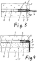
- Fig. 2 and 3 to illustrate precursors of the finished edge bond of the vacuum insulating glass component according to Fig. 1 ,
- Fig. 2 shows the two still individual discs cover plate 1 and bottom plate 2 with each welded to the edge metal foil strip 5. On the bottom plate 2, the spacers 4 are also already placed.
- Fig. 3 shows the assembled arrangement of the upper disk 1 and lower disk 2 with the metal foil strips 5 welded thereto, the regions of the metal foil strips 5 projecting beyond the disk edges being welded together by the weld seam 7.
- the finished edge bond then forms, as it does in FIG Fig. 1 is shown.
- Fig. 4 shows an arrangement as shown in Fig. 1 however, the lower pane 2 is combined with (or designed as) an additional module, here with a photovoltaic module 10.
- the photovoltaic module 10 forms a composite with the lower pane 2.
- the add-on module made wholly or partly of glass material, the metal foil strips, as in Fig. 4 is shown, as well as in the basic embodiment according to Fig. 1 be attached to the disc space 3 facing sides of the cover plate 1 and the lower plate 2 and the associated additional module.
- the additional module is not suitable for a vacuum-tight attachment of the relevant metal foil strip 5, the in Fig. 5 shown, arrangement described below are selected. In most cases, however, the one disk, here the lower disk, will itself form the additional module through an integrated special function.
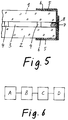
- Fig. 5 shows a modification of the formation of the vacuum-tight edge bond of the arrangement according to Fig. 1 , It differs from the embodiment Fig. 1 in that the metal foil strips 5 are not attached to the mutually facing sides of the individual glass panes 1 and 2, but on their outer sides.
- This embodiment according to Fig. 5 is possible and also equivalent in terms of the quality of the vacuum-tight edge seal as the embodiment according to Fig. 1 but it requires that the two outer surfaces of the finished vacuum insulating glass component are not completely smooth up to the peripheral edge, but at the edge have a small area elevation because of the metal foil strips 5 attached there. This could be disturbing in some applications, which is why this second embodiment Fig. 5 less preferred appears.
- the preferred material for the edge foil strips 5 in all embodiments is stainless steel.
- the outer gap between the individual sheets 1 and 2 and the metal foil strip 5 attached thereto may be sealed to the glass plate surface by a filling material 9 in the region between the respective single-wafer outer edge and the joint region.
- This has two functions. It ensures long-term vacuum tightness by protecting the weld between the metal foil strips and the glass against external influences and reducing mechanical stress. And it protects the window edges when bending the welded metal foil strips from strong mechanical stress.
- Fig. 6 shows in the form of a schematic block diagram the sequence of a preferred method for the production of vacuum insulating glass components according to the invention described above.
- a first method step A the preparation of the two individual glass panes takes place under atmospheric conditions. This includes connecting the individual disks to the metal foil strips and attaching the spacers to the bottom plate and optionally applying the getter material.
- the second process step B is the cleaning of the two individual disks, in particular the removal of water molecules from the disk surfaces. Especially coatings of the disks bind water molecules, which are difficult to remove. In the prior art, this requires longer heating to high temperatures, which is undesirable since high, especially longer-acting temperatures destroy high-quality coatings for reducing the emissivity (so-called low-E layers) and also destroy the glass structure, for example in the case of safety glass. as already explained above.
- This cleaning step is therefore carried out in the inventive method without exposure to temperature by Ionscuttering (bombardment of the glass pane surface with a Tonenwolke), wherein the ions absorb the moisture and carry away, or by plasma cleaning, also called plasma etching.
- This process step takes place in a first vacuum chamber under constant suction to remove the moisture released from the disc surfaces. It is very important that in each case both sides of each individual pane are cleaned of moisture, thus also in each case that side, which does not limit the evacuated space between panes. This is necessary because any application of moisture into the high vacuum chamber, in which the laser welding of the metal foil strip takes place, must be carefully avoided, otherwise the high vacuum is impaired.
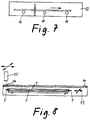
- Fig. 7 schematically shows the cleaning step according to step B in the first vacuum chamber by ion-cutting or vacuum etching from both sides of the plate, wherein the ion-cutting or vacuum etching in each case inline across the plate width, while the glass on transport means 11 passes through this first vacuum chamber 12.
- the third process step C is the laser welding of the metal foil strips in a second vacuum chamber 13, which is shown schematically in FIG Fig. 8 is shown in section.
- the lower disk 2 is first introduced into the vacuum chamber 13 and then introduced and placed the upper disk.
- the vacuum chamber 13 has on its upper side along all four edge regions each respective linear window 14, which of course are interrupted to the necessary extent by bridges required for the integrity of the top wall of the vacuum chamber 13 of supporting material.
- a laser gun 15 is disposed outside, namely above the vacuum chamber 13 and movable along the windows 14 to direct a laser beam through the windows 14 on the metal foil strips to be welded.
- the disk assembly is slidably disposed within the vacuum chamber 13 on a corresponding carriage in the disk plane, since due to the design-related interruptions of the window 14, a certain displaceability of the disk assembly in addition to the mobility of the laser gun is necessary
- the laser gun 15 is located outside the vacuum chamber 13 and is movable along the windows 14, there is no need for mirrors and any other optical elements or mechanisms within the vacuum chamber so that they can be stirred with the least possible volume. Their necessary length and width are based on the dimensions of the largest disk assemblies to be welded therein, and the height of the vacuum chamber is limited only by the thickness of the disk assembly and the necessary height of the disk support Sled determined. Because of the movability of the laser gun 15 but also outside the vacuum chamber otherwise necessary complicated laser optical devices, in particular mirror mechanisms, and simplify the device.
- step D after removing the disk arrangement with the laser-welded metal foil strips from the second vacuum chamber 13, the final after-treatment of the edge areas, namely by introducing the filler material 9, bending the laser-welded protruding portions of the metal foil strips, and if desired applying a protective cover on the finished edge seal.
Landscapes
- Engineering & Computer Science (AREA)
- Civil Engineering (AREA)
- Structural Engineering (AREA)
- Joining Of Glass To Other Materials (AREA)
- Securing Of Glass Panes Or The Like (AREA)
Claims (10)
- Elément de construction en verre isolant sous vide, avec une première feuille de verre (1) et une seconde feuille de verre (2) appuyées l'une à l'autre au moyens des éléments d'écartement (4), enfermant entre elles un mince espace intermédiaire (3) évacué, et étant fermées au niveau de leurs bords par une liaison périphérique étanche au vide,
la liaison périphérique étant formée à partir des bandes de feuille de métal (5), dont premières bandes de feuille de métal (5) sont reliées de manière étanche au vide avec les bords de la première feuille de verre (1), et dont secondes bandes de feuille de métal (5) avec les bords de la seconde feuille de verre (2), dans lequel les premières et secondes bandes de feuille de métal sont soudées les unes avec les autres,
caractérisé en ce que les zones des premières et secondes bandes de feuille de métal (5) qui dépassent des bords périphériques de la feuille de verre (1, 2) respective sont comprimées et soudées les unes avec les autres par soudage au laser, et en ce que les zones dépassantes des premières et secondes bandes de feuille de métal comprimées et soudées les unes avec les autres par soudage au laser sont pliées vers l'un ou vers l'autre côté de l'élément de construction. - Elément de construction en verre isolant sous vide selon la revendication 1, dans lequel les bandes de feuille de métal (5) sont reliées avec la feuille de verre (1, 2) respective par soudage aux ultrasons, une mince bande de feuille d'aluminium (6) étant disposée entre la bande de feuille de métal (5) respective et la feuille de verre (1, 2) respective, la bande de feuille d'aluminium respectivement étant reliée avec la surface de verre de l'un côté, et avec la bande de feuille de métal (5) de l'autre côté, en chaque cas par soudage aux ultrasons de manière étanche au vide.
- Elément de construction en verre isolant sous vide selon la revendication 1, dans lequel les bandes de feuille de métal (5) sont reliées avec la feuille de verre (1, 2) respective par soudage au moyen d'une brasure de verre.
- Elément de construction en verre isolant sous vide selon l'une quelconque des revendications 1 à 3, dans lequel un matériau getter (8) est appliqué sur au moins une des bandes de feuille de métal (5), de sorte que, après le soudage des bandes de feuille de métal, il est disposé sur le côté du cordon de soudure (7) entre les bandes de feuille de métal (5) tourné vers l'espace intermédiaire (3) évacué entre les deux feuilles de verre (1, 2).
- Elément de construction en verre isolant sous vide selon l'une quelconque des revendications 1 à 4, dans lequel les bandes de feuille de métal (5) sont reliées avec les feuilles de verre (1, 2) respectivement sur les côtés de celles-ci tournés l'un vers l'autre.
- Elément de construction en verre isolant sous vide selon l'une quelconque des revendications 1 à 5, dans lequel les bandes de feuille de métal (5) sont en acier inoxydable.
- Elément de construction en verre isolant sous vide selon l'une quelconque des revendications 1 à 6, dans lequel les espaces de séparation entre les bandes de feuille de métal (5) et les surfaces de verre tournés vers l'extérieur sont scellés au moyen d'un matériau de remplissage (9) en dehors de la zone de soudure de la bande de feuille de métal et la surface de verre.
- Elément de construction en verre isolant sous vide selon l'une quelconque des revendications 1 à 7, dans lequel la première ou la seconde feuille de verre est combinée avec un élément additionnel, à savoir l'un d'un module solaire, un module photovoltaïque et un autre élément, ou est elle-même configurée sous forme d'un tel élément.
- Procédé pour la fabrication d'un élément de construction en verre isolant sous vide selon l'une quelconque des revendications 1 à 8, dans lequel les feuilles de verre (1, 2) préparées, avec les bandes de feuille de métal (5) appliquées à celles-ci, sont introduites dans une chambre à vide et placées l'une au dessus de l'autre dans celle-ci, et dans lequel la soudure des zones dépassantes et comprimées des bandes de feuille de métal est effectuée à l'intérieur de la chambre à vide (13) par un faisceau laser généré en dehors de la chambre à vide et se déplaçant le long de la bande de feuille de métal qui est introduit dans la chambre à vide (13) à travers des fenêtres (14) s'étendant sous forme de ligne, et dans lequel les zones soudées et dépassantes des bandes de feuille de métal sont pliées vers l'un ou vers l'autre côté de l'élément de construction.
- Procédé selon la revendication 9, dans lequel, avant leur introduction dans la chambre à vide (13), où les bandes de feuille de métal (5) sont soudées, les deux feuilles de verre (1, 2) sont nettoyées dans une autre chambre à vide (12) des deux côtés par pulvérisation ionique ou par gravure à plasma pour éliminer toute humidité.
Priority Applications (8)
| Application Number | Priority Date | Filing Date | Title |
|---|---|---|---|
| PT70072533T PT1978199T (pt) | 2007-04-05 | 2007-04-05 | Elemento de construção com vidro isolado sob vácuo, bem como procedimento e equipamento para o seu fabrico |
| PL07007253T PL1978199T3 (pl) | 2007-04-05 | 2007-04-05 | Element budowlany z izolowaną próżniowo szybą zespoloną oraz sposób i urządzenie do jego wytwarzania |
| DK07007253.3T DK1978199T3 (en) | 2007-04-05 | 2007-04-05 | The vacuum insulating glass construction element as well as method and device for its production, |
| ES07007253.3T ES2588000T3 (es) | 2007-04-05 | 2007-04-05 | Elemento constructivo de vidrio de aislamiento por vacío así como procedimiento y dispositivo para su producción |
| EP07007253.3A EP1978199B1 (fr) | 2007-04-05 | 2007-04-05 | Composant en verre isolant du vide et procédé et dispositif de fabrication |
| US12/079,891 US20080245011A1 (en) | 2007-04-05 | 2008-03-28 | Vacuum insulated glass building component and method and apparatus for its manufacture |
| CA002627778A CA2627778A1 (fr) | 2007-04-05 | 2008-04-01 | Element de construction de vitrage sous vide et methode et appareillage de fabrication connexe |
| CN2008100909057A CN101302081B (zh) | 2007-04-05 | 2008-04-01 | 真空绝缘玻璃构件以及其制造方法和装置 |
Applications Claiming Priority (1)
| Application Number | Priority Date | Filing Date | Title |
|---|---|---|---|
| EP07007253.3A EP1978199B1 (fr) | 2007-04-05 | 2007-04-05 | Composant en verre isolant du vide et procédé et dispositif de fabrication |
Publications (2)
| Publication Number | Publication Date |
|---|---|
| EP1978199A1 EP1978199A1 (fr) | 2008-10-08 |
| EP1978199B1 true EP1978199B1 (fr) | 2016-05-25 |
Family
ID=39363995
Family Applications (1)
| Application Number | Title | Priority Date | Filing Date |
|---|---|---|---|
| EP07007253.3A Active EP1978199B1 (fr) | 2007-04-05 | 2007-04-05 | Composant en verre isolant du vide et procédé et dispositif de fabrication |
Country Status (8)
| Country | Link |
|---|---|
| US (1) | US20080245011A1 (fr) |
| EP (1) | EP1978199B1 (fr) |
| CN (1) | CN101302081B (fr) |
| CA (1) | CA2627778A1 (fr) |
| DK (1) | DK1978199T3 (fr) |
| ES (1) | ES2588000T3 (fr) |
| PL (1) | PL1978199T3 (fr) |
| PT (1) | PT1978199T (fr) |
Families Citing this family (45)
| Publication number | Priority date | Publication date | Assignee | Title |
|---|---|---|---|---|
| US8512829B2 (en) * | 2007-12-14 | 2013-08-20 | Guardian Industries Corp. | Metal-inclusive edge seal for vacuum insulating glass unit, and/or method of making the same |
| DE102008025945A1 (de) * | 2008-05-30 | 2009-12-03 | Fraunhofer-Gesellschaft zur Förderung der angewandten Forschung e.V. | Verfahren zur Herstellung eines vakuumdichten Verbundes zwischen einer Glasscheibe und einem Metallrahmen sowie Glasscheibenverbund |
| KR100990858B1 (ko) | 2008-09-17 | 2010-10-29 | 주식회사 에피온 | 진공창호유리 및 그 제조방법 |
| DE202009012136U1 (de) | 2009-09-07 | 2009-11-26 | Grenzebach Maschinenbau Gmbh | Vorrichtung zum Vakuum-dichten Aneinanderfügen von Glasplatten |
| DE102009040422A1 (de) | 2009-09-07 | 2011-03-17 | Grenzebach Maschinenbau Gmbh | Verfahren und Vorrichtung zum Vakuum-dichten Aneinanderfügen von Glasplatten |
| EA022427B1 (ru) * | 2009-11-18 | 2015-12-30 | Агк Гласс Юроп | Способ изготовления изоляционного остекления |
| CN102079619B (zh) * | 2009-11-27 | 2012-02-15 | 洛阳兰迪玻璃机器股份有限公司 | 一种玻璃板复合封接方法 |
| DE102010021127B4 (de) | 2010-05-21 | 2021-11-04 | Grenzebach Maschinenbau Gmbh | Verfahren zum Herstellen von Mehrscheiben-Isolierglas mit einer Hochvakuum-Isolierung |
| DE202010007079U1 (de) | 2010-05-21 | 2011-08-01 | Grenzebach Maschinenbau Gmbh | Vorrichtung zum Herstellen von Mehrscheiben-Isolierglas mit einer Hochvakuum-Isolierung |
| KR101209946B1 (ko) | 2010-09-10 | 2012-12-10 | 한국건설기술연구원 | 진공창 및 진공창의 제조방법 |
| CN102476926B (zh) * | 2010-11-23 | 2013-12-18 | 洛阳兰迪玻璃机器股份有限公司 | 一种真空玻璃封接装置 |
| WO2012075723A1 (fr) * | 2010-12-10 | 2012-06-14 | Luoyang Landglass Technology Co., Ltd. | Verre à vide ayant un trou de montage |
| WO2012075724A1 (fr) * | 2010-12-10 | 2012-06-14 | Luoyang Landglass Technology Co., Ltd. | Composant de verre à vide |
| CN102617025B (zh) * | 2011-01-31 | 2014-06-25 | 洛阳兰迪玻璃机器股份有限公司 | 一种制作真空玻璃构件时获得真空的方法 |
| US8679599B2 (en) * | 2011-03-29 | 2014-03-25 | Corning Incorporated | Light-weight strengthened, low-emittance vacuum insulated glass (VIG) windows |
| CN102795763B (zh) * | 2011-05-24 | 2015-01-21 | 洛阳兰迪玻璃机器股份有限公司 | 一种真空玻璃构件连续加工装置 |
| DE102011102843B4 (de) * | 2011-05-30 | 2022-05-25 | Grenzebach Maschinenbau Gmbh | +Vakuum - Isolierglas mit erhöhter Standfestigkeit und Verfahren zu seiner Herstellung |
| CN102285767B (zh) * | 2011-05-31 | 2013-06-05 | 朱雷 | 含有金属边的真空玻璃及其制备方法 |
| BE1020214A3 (fr) * | 2011-09-07 | 2013-06-04 | Agc Glass Europe | Panneau de vitrage comprenant des feuilles de verres associees ensemble par l'intermediaire d'espaceurs et procede de fabrication correspondants. |
| EP2592209A1 (fr) | 2011-11-11 | 2013-05-15 | Bayer MaterialScience AG | Panneau isolant sous vide |
| DE102012104360A1 (de) | 2012-05-21 | 2013-11-21 | Aerogas Gmbh | Vakuumisolierglaseinheit und deren Herstellung |
| US9346710B2 (en) | 2012-05-29 | 2016-05-24 | Corning Incorporated | Sheet glass product fabrication with growth-limited glass bump spacers |
| US9428952B2 (en) * | 2012-05-31 | 2016-08-30 | Guardian Industries Corp. | Vacuum insulated glass (VIG) window unit with reduced seal height variation and method for making same |
| CN104003628A (zh) * | 2013-02-26 | 2014-08-27 | 中国建材检验认证集团股份有限公司 | 具金属封边结构的真空玻璃及其制作方法 |
| CN104773962B (zh) * | 2014-01-09 | 2017-08-01 | 洛阳北方玻璃技术股份有限公司 | 真空玻璃封接结构以及半成品及其封接方法 |
| CN104773963A (zh) * | 2014-01-09 | 2015-07-15 | 洛阳北方玻璃技术股份有限公司 | 真空玻璃封接结构以及半成品及其封接方法 |
| CA2938659C (fr) | 2014-02-03 | 2021-11-09 | Peter Petit | Systeme de joint hermetique flexible pour ensemble de panneaux de verre plat |
| FI127237B (en) * | 2014-02-17 | 2018-02-15 | Savo Solar Oy | Solvärmeabsorbatorelement |
| KR101453307B1 (ko) | 2014-04-08 | 2014-10-23 | 주식회사 에피온 | 진공 유리 패널 모듈 |
| WO2016017709A1 (fr) * | 2014-07-30 | 2016-02-04 | 旭硝子株式会社 | Procédé de production de verre à vide multicouche et verre à vide multicouche |
| US9359252B1 (en) | 2015-07-24 | 2016-06-07 | Corning Incorporated | Methods for controlled laser-induced growth of glass bumps on glass articles |
| US20170022100A1 (en) | 2015-07-24 | 2017-01-26 | Corning Incorporated | Glass bumps on glass articles and methods of laser-induced growth |
| JPWO2017056422A1 (ja) * | 2015-09-29 | 2018-07-26 | パナソニックIpマネジメント株式会社 | ガラスパネルユニットおよびガラス窓 |
| EA201892127A1 (ru) | 2016-04-05 | 2019-07-31 | Агк Гласс Юроп | Способ изготовления вакуумного изоляционного стеклопакета |
| US11162688B2 (en) | 2017-02-06 | 2021-11-02 | Schott Gemtron Corp. | Thermally insulating glass laminates with a plurality of glass spacers submerged in a coating layer to form a sealed cavity of gas molecules |
| MX2019009317A (es) * | 2017-02-06 | 2019-09-19 | Schott Gemtron Corp | Laminados de vidrio termicamente aislantes con una pluralidad de separadores de vidrio sumergidos en una capa de revestimiento para formar una cavidad sellada de moleculas de gas. |
| US10575660B2 (en) * | 2017-08-29 | 2020-03-03 | Anthony, Inc. | Glass assembly with clear edging |
| JP7063740B2 (ja) * | 2018-06-18 | 2022-05-09 | 日本板硝子株式会社 | 真空ガラスパネル |
| WO2020118673A1 (fr) * | 2018-12-11 | 2020-06-18 | 淄博环能海臣环保技术服务有限公司 | Verre de régulation sous vide avec métal brasé à un cadre de support de tension de verre et cadre en acier inoxydable |
| CN111302656B (zh) * | 2018-12-11 | 2023-11-24 | 淄博环能海臣环保技术服务有限公司 | 玻璃及不锈钢边框与拉伸支撑边框金属钎焊夹层真空玻璃 |
| CN109734333B (zh) * | 2019-03-12 | 2021-07-27 | 河南科技大学 | 一种真空玻璃一体化支撑物制备装置 |
| CN110188445B (zh) * | 2019-05-24 | 2023-06-27 | 海南师范大学 | 一种隔音真空玻璃的支撑架的设计方法 |
| CN111273491B (zh) * | 2020-03-27 | 2022-07-12 | 武汉华星光电技术有限公司 | 液晶显示面板和显示装置 |
| KR20230025404A (ko) * | 2020-06-11 | 2023-02-21 | 브이-글래스 아이엔씨. | 2단 기밀 봉지 및 그 제조방법 |
| CN112901031A (zh) * | 2021-02-07 | 2021-06-04 | 东莞帕萨电子装备有限公司 | 真空玻璃生产线及加工工艺 |
Family Cites Families (28)
| Publication number | Priority date | Publication date | Assignee | Title |
|---|---|---|---|---|
| US3114179A (en) * | 1960-12-01 | 1963-12-17 | Window Products Inc | Heat-insulated metal-framed closure |
| US3105274A (en) * | 1961-05-19 | 1963-10-01 | Armstrong Patents Co Ltd | Multiple glass pane glazing unit and method of fabrication |
| US3360849A (en) * | 1962-03-01 | 1968-01-02 | Perkin Elmer Corp | Metal to glass welding |
| US3261139A (en) * | 1964-05-14 | 1966-07-19 | Polarpane Corp | Multiple glazed unit |
| US4004388A (en) * | 1974-02-21 | 1977-01-25 | Ppg Industries, Inc. | Window panel edge construction |
| US3971178A (en) * | 1974-03-25 | 1976-07-27 | Ppg Industries, Inc. | Add-on multiple glazing with hygroscopic material |
| US5005557A (en) * | 1985-11-29 | 1991-04-09 | Baechli Emil | Heat-insulating building and/or light element |
| JPS62168693A (ja) * | 1986-01-18 | 1987-07-24 | Yoshiaki Arata | 真空レ−ザ溶接法 |
| US5124185A (en) * | 1989-10-03 | 1992-06-23 | Ppg Industries, Inc. | Vacuum insulating unit |
| GB2276270A (en) * | 1993-03-18 | 1994-09-21 | Ibm | Spacers for flat panel displays |
| AUPM888994A0 (en) * | 1994-10-19 | 1994-11-10 | University Of Sydney, The | Design improvement to vacuum glazing |
| US5646687A (en) * | 1994-12-29 | 1997-07-08 | Lucent Technologies Inc. | Temporally-pipelined predictive encoder/decoder circuit and method |
| FR2742179B1 (fr) * | 1995-12-06 | 1998-01-16 | Saint Gobain Vitrage | Structure portante en verre |
| CN1194631A (zh) * | 1996-04-03 | 1998-09-30 | 日本板硝子株式会社 | 复层窗玻璃 |
| US6204523B1 (en) * | 1998-11-06 | 2001-03-20 | Lumileds Lighting, U.S., Llc | High stability optical encapsulation and packaging for light-emitting diodes in the green, blue, and near UV range |
| CN1077554C (zh) * | 1998-12-17 | 2002-01-09 | 张入通 | 玻璃-金属的铝丝热压封接工艺 |
| WO2001016045A1 (fr) * | 1999-08-27 | 2001-03-08 | Qingdao Synergy Technology Appliance Co., Ltd. | Procede de fabrication de vitrage sous vide et systeme mecanique d'application |
| US6686676B2 (en) * | 2001-04-30 | 2004-02-03 | General Electric Company | UV reflectors and UV-based light sources having reduced UV radiation leakage incorporating the same |
| US6989412B2 (en) * | 2001-06-06 | 2006-01-24 | Henkel Corporation | Epoxy molding compounds containing phosphor and process for preparing such compositions |
| US6841647B2 (en) * | 2001-11-06 | 2005-01-11 | National Starch And Chemical Investment Holding Corporation | Fluid resistant silicone encapsulant |
| US6632491B1 (en) * | 2002-05-21 | 2003-10-14 | Guardian Industries Corp. | IG window unit and method of making the same |
| FR2848333B1 (fr) * | 2002-12-04 | 2005-04-01 | Saint Gobain | Materiau de jonction entre des espaceurs et un substrat verrier |
| US7160972B2 (en) * | 2003-02-19 | 2007-01-09 | Nusil Technology Llc | Optically clear high temperature resistant silicone polymers of high refractive index |
| JP2004352567A (ja) * | 2003-05-29 | 2004-12-16 | Nippon Sheet Glass Co Ltd | 断熱・遮熱性ガラスパネル |
| CN1556540A (zh) * | 2003-12-30 | 2004-12-22 | 中国科学院上海微系统与信息技术研究 | 场发射显示器件的高真空封装方法 |
| US7261441B2 (en) * | 2004-02-27 | 2007-08-28 | Avago Technologies Ecbu Ip (Singapore) Pte. Ltd. | LED device and method for directing LED light |
| US7229934B2 (en) * | 2004-10-18 | 2007-06-12 | International Business Machines Corporation | Porous organosilicates with improved mechanical properties |
| CN100340513C (zh) * | 2005-06-23 | 2007-10-03 | 郑顺清 | 真空玻璃板 |
-
2007
- 2007-04-05 PL PL07007253T patent/PL1978199T3/pl unknown
- 2007-04-05 ES ES07007253.3T patent/ES2588000T3/es active Active
- 2007-04-05 EP EP07007253.3A patent/EP1978199B1/fr active Active
- 2007-04-05 DK DK07007253.3T patent/DK1978199T3/en active
- 2007-04-05 PT PT70072533T patent/PT1978199T/pt unknown
-
2008
- 2008-03-28 US US12/079,891 patent/US20080245011A1/en not_active Abandoned
- 2008-04-01 CA CA002627778A patent/CA2627778A1/fr not_active Abandoned
- 2008-04-01 CN CN2008100909057A patent/CN101302081B/zh not_active Expired - Fee Related
Also Published As
| Publication number | Publication date |
|---|---|
| CN101302081B (zh) | 2012-01-11 |
| CN101302081A (zh) | 2008-11-12 |
| EP1978199A1 (fr) | 2008-10-08 |
| US20080245011A1 (en) | 2008-10-09 |
| CA2627778A1 (fr) | 2008-10-05 |
| ES2588000T3 (es) | 2016-10-28 |
| PL1978199T3 (pl) | 2017-01-31 |
| DK1978199T3 (en) | 2016-09-05 |
| PT1978199T (pt) | 2016-08-29 |
Similar Documents
| Publication | Publication Date | Title |
|---|---|---|
| EP1978199B1 (fr) | Composant en verre isolant du vide et procédé et dispositif de fabrication | |
| DE102009058789B4 (de) | Wärmedämmendes Verglasungselement und Verfahren zu dessen Herstellung | |
| DE60038288T2 (de) | Verfahren zur versiegelung von glas | |
| DE102010021127B4 (de) | Verfahren zum Herstellen von Mehrscheiben-Isolierglas mit einer Hochvakuum-Isolierung | |
| EP1820931A1 (fr) | Vitrage coupe-feu | |
| WO1999015753A1 (fr) | Profile d'ecartement pour ensemble vitrage isolant | |
| DE102012104360A1 (de) | Vakuumisolierglaseinheit und deren Herstellung | |
| EP2403716A1 (fr) | Toit en verre intégral pour un véhicule automobile | |
| EP2190665A1 (fr) | Élément stratifié et procédé pour la fabrication de sa fixation | |
| DE102010025784A1 (de) | Dämmelement und Verfahren zur Herstellung eines Dämmelementes | |
| DE2842400A1 (de) | Solarenergiekollektor mit linsenraster | |
| EP0528354B1 (fr) | Vitrage isolant blindé | |
| DE19805265A1 (de) | Abstandhalterprofil für Isolierscheibeneinheit | |
| EP2312104A1 (fr) | Porte coupe-feu | |
| CH696408A5 (de) | Mehrscheiben-Isolierverglasung. | |
| DE202011050015U1 (de) | Solarkollektor | |
| EP2405093A2 (fr) | Verrière ignifuge modulaire | |
| EP3527770B1 (fr) | Méthode de fabrication d'un système de fixation des vitres de verre sur un cadre en bois sans perte au niveau d'isolation | |
| DE10161659C1 (de) | Koksofentür mit Membrane | |
| EP2829681B1 (fr) | Vitrage isolant | |
| DE202018100885U1 (de) | System zur Glasscheiben-Fixierung mit Holzrahmen ohne Trennverlust | |
| DE2502264A1 (de) | Verglasungseinheit | |
| DE102022130805B3 (de) | Isolierglaselement, Kühlmöbel mit diesem und Verfahren zum Herstellen eines Isolierglaselementes | |
| DE102010017447A1 (de) | Feuerschutztür | |
| DE102021113001A1 (de) | Isolierglaselement, Kühlmöbel mit diesem und Verfahren zum Herstellen eines Isolierglaselements |
Legal Events
| Date | Code | Title | Description |
|---|---|---|---|
| PUAI | Public reference made under article 153(3) epc to a published international application that has entered the european phase |
Free format text: ORIGINAL CODE: 0009012 |
|
| AK | Designated contracting states |
Kind code of ref document: A1 Designated state(s): AT BE BG CH CY CZ DE DK EE ES FI FR GB GR HU IE IS IT LI LT LU LV MC MT NL PL PT RO SE SI SK TR |
|
| AX | Request for extension of the european patent |
Extension state: AL BA HR MK RS |
|
| 17P | Request for examination filed |
Effective date: 20081124 |
|
| 17Q | First examination report despatched |
Effective date: 20090115 |
|
| RIN1 | Information on inventor provided before grant (corrected) |
Inventor name: GLASER SIEGFRIED Inventor name: FRIEDL WOLFGANG |
|
| AKX | Designation fees paid |
Designated state(s): AT BE BG CH CY CZ DE DK EE ES FI FR GB GR HU IE IS IT LI LT LU LV MC MT NL PL PT RO SE SI SK TR |
|
| GRAP | Despatch of communication of intention to grant a patent |
Free format text: ORIGINAL CODE: EPIDOSNIGR1 |
|
| GRAS | Grant fee paid |
Free format text: ORIGINAL CODE: EPIDOSNIGR3 |
|
| INTG | Intention to grant announced |
Effective date: 20160209 |
|
| GRAA | (expected) grant |
Free format text: ORIGINAL CODE: 0009210 |
|
| AK | Designated contracting states |
Kind code of ref document: B1 Designated state(s): AT BE BG CH CY CZ DE DK EE ES FI FR GB GR HU IE IS IT LI LT LU LV MC MT NL PL PT RO SE SI SK TR |
|
| REG | Reference to a national code |
Ref country code: GB Ref legal event code: FG4D Free format text: NOT ENGLISH |
|
| REG | Reference to a national code |
Ref country code: CH Ref legal event code: EP |
|
| REG | Reference to a national code |
Ref country code: IE Ref legal event code: FG4D Free format text: LANGUAGE OF EP DOCUMENT: GERMAN Ref country code: AT Ref legal event code: REF Ref document number: 802487 Country of ref document: AT Kind code of ref document: T Effective date: 20160615 |
|
| REG | Reference to a national code |
Ref country code: DE Ref legal event code: R096 Ref document number: 502007014837 Country of ref document: DE |
|
| REG | Reference to a national code |
Ref country code: PT Ref legal event code: SC4A Ref document number: 1978199 Country of ref document: PT Date of ref document: 20160829 Kind code of ref document: T Free format text: AVAILABILITY OF NATIONAL TRANSLATION Effective date: 20160822 |
|
| REG | Reference to a national code |
Ref country code: NL Ref legal event code: FP |
|
| REG | Reference to a national code |
Ref country code: DK Ref legal event code: T3 Effective date: 20160830 |
|
| REG | Reference to a national code |
Ref country code: SE Ref legal event code: TRGR |
|
| REG | Reference to a national code |
Ref country code: LT Ref legal event code: MG4D |
|
| REG | Reference to a national code |
Ref country code: ES Ref legal event code: FG2A Ref document number: 2588000 Country of ref document: ES Kind code of ref document: T3 Effective date: 20161028 |
|
| PG25 | Lapsed in a contracting state [announced via postgrant information from national office to epo] |
Ref country code: LT Free format text: LAPSE BECAUSE OF FAILURE TO SUBMIT A TRANSLATION OF THE DESCRIPTION OR TO PAY THE FEE WITHIN THE PRESCRIBED TIME-LIMIT Effective date: 20160525 |
|
| PG25 | Lapsed in a contracting state [announced via postgrant information from national office to epo] |
Ref country code: LV Free format text: LAPSE BECAUSE OF FAILURE TO SUBMIT A TRANSLATION OF THE DESCRIPTION OR TO PAY THE FEE WITHIN THE PRESCRIBED TIME-LIMIT Effective date: 20160525 Ref country code: GR Free format text: LAPSE BECAUSE OF FAILURE TO SUBMIT A TRANSLATION OF THE DESCRIPTION OR TO PAY THE FEE WITHIN THE PRESCRIBED TIME-LIMIT Effective date: 20160826 |
|
| PG25 | Lapsed in a contracting state [announced via postgrant information from national office to epo] |
Ref country code: SK Free format text: LAPSE BECAUSE OF FAILURE TO SUBMIT A TRANSLATION OF THE DESCRIPTION OR TO PAY THE FEE WITHIN THE PRESCRIBED TIME-LIMIT Effective date: 20160525 Ref country code: EE Free format text: LAPSE BECAUSE OF FAILURE TO SUBMIT A TRANSLATION OF THE DESCRIPTION OR TO PAY THE FEE WITHIN THE PRESCRIBED TIME-LIMIT Effective date: 20160525 Ref country code: RO Free format text: LAPSE BECAUSE OF FAILURE TO SUBMIT A TRANSLATION OF THE DESCRIPTION OR TO PAY THE FEE WITHIN THE PRESCRIBED TIME-LIMIT Effective date: 20160525 Ref country code: CZ Free format text: LAPSE BECAUSE OF FAILURE TO SUBMIT A TRANSLATION OF THE DESCRIPTION OR TO PAY THE FEE WITHIN THE PRESCRIBED TIME-LIMIT Effective date: 20160525 |
|
| REG | Reference to a national code |
Ref country code: DE Ref legal event code: R097 Ref document number: 502007014837 Country of ref document: DE |
|
| PLBE | No opposition filed within time limit |
Free format text: ORIGINAL CODE: 0009261 |
|
| STAA | Information on the status of an ep patent application or granted ep patent |
Free format text: STATUS: NO OPPOSITION FILED WITHIN TIME LIMIT |
|
| 26N | No opposition filed |
Effective date: 20170228 |
|
| PG25 | Lapsed in a contracting state [announced via postgrant information from national office to epo] |
Ref country code: SI Free format text: LAPSE BECAUSE OF FAILURE TO SUBMIT A TRANSLATION OF THE DESCRIPTION OR TO PAY THE FEE WITHIN THE PRESCRIBED TIME-LIMIT Effective date: 20160525 |
|
| REG | Reference to a national code |
Ref country code: DK Ref legal event code: EBP Effective date: 20170430 |
|
| REG | Reference to a national code |
Ref country code: CH Ref legal event code: PL |
|
| REG | Reference to a national code |
Ref country code: NL Ref legal event code: MM Effective date: 20170501 |
|
| GBPC | Gb: european patent ceased through non-payment of renewal fee |
Effective date: 20170405 |
|
| REG | Reference to a national code |
Ref country code: IE Ref legal event code: MM4A |
|
| REG | Reference to a national code |
Ref country code: FR Ref legal event code: ST Effective date: 20171229 |
|
| PG25 | Lapsed in a contracting state [announced via postgrant information from national office to epo] |
Ref country code: NL Free format text: LAPSE BECAUSE OF NON-PAYMENT OF DUE FEES Effective date: 20170501 Ref country code: MC Free format text: LAPSE BECAUSE OF FAILURE TO SUBMIT A TRANSLATION OF THE DESCRIPTION OR TO PAY THE FEE WITHIN THE PRESCRIBED TIME-LIMIT Effective date: 20160525 Ref country code: FR Free format text: LAPSE BECAUSE OF NON-PAYMENT OF DUE FEES Effective date: 20170502 Ref country code: FI Free format text: LAPSE BECAUSE OF NON-PAYMENT OF DUE FEES Effective date: 20170405 |
|
| PG25 | Lapsed in a contracting state [announced via postgrant information from national office to epo] |
Ref country code: GB Free format text: LAPSE BECAUSE OF NON-PAYMENT OF DUE FEES Effective date: 20170405 Ref country code: LU Free format text: LAPSE BECAUSE OF NON-PAYMENT OF DUE FEES Effective date: 20170405 Ref country code: LI Free format text: LAPSE BECAUSE OF NON-PAYMENT OF DUE FEES Effective date: 20170430 Ref country code: SE Free format text: LAPSE BECAUSE OF NON-PAYMENT OF DUE FEES Effective date: 20170406 Ref country code: CH Free format text: LAPSE BECAUSE OF NON-PAYMENT OF DUE FEES Effective date: 20170430 |
|
| REG | Reference to a national code |
Ref country code: BE Ref legal event code: MM Effective date: 20170430 |
|
| PG25 | Lapsed in a contracting state [announced via postgrant information from national office to epo] |
Ref country code: DK Free format text: LAPSE BECAUSE OF NON-PAYMENT OF DUE FEES Effective date: 20170430 Ref country code: IE Free format text: LAPSE BECAUSE OF NON-PAYMENT OF DUE FEES Effective date: 20170405 |
|
| PG25 | Lapsed in a contracting state [announced via postgrant information from national office to epo] |
Ref country code: IT Free format text: LAPSE BECAUSE OF NON-PAYMENT OF DUE FEES Effective date: 20170405 Ref country code: BE Free format text: LAPSE BECAUSE OF NON-PAYMENT OF DUE FEES Effective date: 20170430 Ref country code: PT Free format text: LAPSE BECAUSE OF NON-PAYMENT OF DUE FEES Effective date: 20180105 |
|
| REG | Reference to a national code |
Ref country code: AT Ref legal event code: MM01 Ref document number: 802487 Country of ref document: AT Kind code of ref document: T Effective date: 20170405 |
|
| REG | Reference to a national code |
Ref country code: ES Ref legal event code: FD2A Effective date: 20180705 |
|
| PG25 | Lapsed in a contracting state [announced via postgrant information from national office to epo] |
Ref country code: ES Free format text: LAPSE BECAUSE OF NON-PAYMENT OF DUE FEES Effective date: 20170406 |
|
| PG25 | Lapsed in a contracting state [announced via postgrant information from national office to epo] |
Ref country code: AT Free format text: LAPSE BECAUSE OF NON-PAYMENT OF DUE FEES Effective date: 20170405 |
|
| PG25 | Lapsed in a contracting state [announced via postgrant information from national office to epo] |
Ref country code: MT Free format text: LAPSE BECAUSE OF FAILURE TO SUBMIT A TRANSLATION OF THE DESCRIPTION OR TO PAY THE FEE WITHIN THE PRESCRIBED TIME-LIMIT Effective date: 20160525 |
|
| PG25 | Lapsed in a contracting state [announced via postgrant information from national office to epo] |
Ref country code: PL Free format text: LAPSE BECAUSE OF NON-PAYMENT OF DUE FEES Effective date: 20170405 |
|
| PG25 | Lapsed in a contracting state [announced via postgrant information from national office to epo] |
Ref country code: HU Free format text: LAPSE BECAUSE OF FAILURE TO SUBMIT A TRANSLATION OF THE DESCRIPTION OR TO PAY THE FEE WITHIN THE PRESCRIBED TIME-LIMIT; INVALID AB INITIO Effective date: 20070405 |
|
| PG25 | Lapsed in a contracting state [announced via postgrant information from national office to epo] |
Ref country code: BG Free format text: LAPSE BECAUSE OF FAILURE TO SUBMIT A TRANSLATION OF THE DESCRIPTION OR TO PAY THE FEE WITHIN THE PRESCRIBED TIME-LIMIT Effective date: 20160525 |
|
| PG25 | Lapsed in a contracting state [announced via postgrant information from national office to epo] |
Ref country code: CY Free format text: LAPSE BECAUSE OF NON-PAYMENT OF DUE FEES Effective date: 20160525 |
|
| PG25 | Lapsed in a contracting state [announced via postgrant information from national office to epo] |
Ref country code: TR Free format text: LAPSE BECAUSE OF FAILURE TO SUBMIT A TRANSLATION OF THE DESCRIPTION OR TO PAY THE FEE WITHIN THE PRESCRIBED TIME-LIMIT Effective date: 20160525 |
|
| PG25 | Lapsed in a contracting state [announced via postgrant information from national office to epo] |
Ref country code: IS Free format text: LAPSE BECAUSE OF FAILURE TO SUBMIT A TRANSLATION OF THE DESCRIPTION OR TO PAY THE FEE WITHIN THE PRESCRIBED TIME-LIMIT Effective date: 20160925 |
|
| REG | Reference to a national code |
Ref country code: DE Ref legal event code: R082 Ref document number: 502007014837 Country of ref document: DE Representative=s name: FLEUCHAUS & GALLO PARTNERSCHAFT MBB - PATENT- , DE Ref country code: DE Ref legal event code: R082 Ref document number: 502007014837 Country of ref document: DE Representative=s name: FLEUCHAUS & GALLO PARTNERSCHAFT MBB PATENTANWA, DE |
|
| PGFP | Annual fee paid to national office [announced via postgrant information from national office to epo] |
Ref country code: DE Payment date: 20230419 Year of fee payment: 17 |