EP1962071B1 - Temperaturmesssystem - Google Patents
Temperaturmesssystem Download PDFInfo
- Publication number
- EP1962071B1 EP1962071B1 EP08002565A EP08002565A EP1962071B1 EP 1962071 B1 EP1962071 B1 EP 1962071B1 EP 08002565 A EP08002565 A EP 08002565A EP 08002565 A EP08002565 A EP 08002565A EP 1962071 B1 EP1962071 B1 EP 1962071B1
- Authority
- EP
- European Patent Office
- Prior art keywords
- strand
- temperature sensor
- temperature
- metal
- measurement system
- Prior art date
- Legal status (The legal status is an assumption and is not a legal conclusion. Google has not performed a legal analysis and makes no representation as to the accuracy of the status listed.)
- Not-in-force
Links
- 238000009529 body temperature measurement Methods 0.000 title claims abstract description 37
- 230000031070 response to heat Effects 0.000 claims abstract description 4
- 239000002184 metal Substances 0.000 claims description 73
- 229910052751 metal Inorganic materials 0.000 claims description 73
- 238000009749 continuous casting Methods 0.000 claims description 29
- 238000000034 method Methods 0.000 claims description 26
- 230000004044 response Effects 0.000 claims description 11
- 230000006378 damage Effects 0.000 claims description 7
- 238000012544 monitoring process Methods 0.000 claims description 4
- 239000011241 protective layer Substances 0.000 claims description 4
- 239000000835 fiber Substances 0.000 claims description 2
- 238000001816 cooling Methods 0.000 description 40
- 230000008569 process Effects 0.000 description 13
- 230000008901 benefit Effects 0.000 description 7
- 238000005266 casting Methods 0.000 description 6
- 239000000463 material Substances 0.000 description 6
- 229910000831 Steel Inorganic materials 0.000 description 5
- 230000007812 deficiency Effects 0.000 description 5
- 239000007921 spray Substances 0.000 description 5
- 239000010959 steel Substances 0.000 description 5
- XLYOFNOQVPJJNP-UHFFFAOYSA-N water Substances O XLYOFNOQVPJJNP-UHFFFAOYSA-N 0.000 description 5
- 150000002739 metals Chemical class 0.000 description 4
- 238000010586 diagram Methods 0.000 description 3
- 239000007788 liquid Substances 0.000 description 3
- 238000005259 measurement Methods 0.000 description 3
- 239000002826 coolant Substances 0.000 description 2
- 230000000694 effects Effects 0.000 description 2
- 238000012423 maintenance Methods 0.000 description 2
- 238000004519 manufacturing process Methods 0.000 description 2
- 239000000203 mixture Substances 0.000 description 2
- 238000012986 modification Methods 0.000 description 2
- 230000004048 modification Effects 0.000 description 2
- 230000003287 optical effect Effects 0.000 description 2
- 238000012545 processing Methods 0.000 description 2
- 239000007787 solid Substances 0.000 description 2
- 239000010935 stainless steel Substances 0.000 description 2
- 229910001220 stainless steel Inorganic materials 0.000 description 2
- RYGMFSIKBFXOCR-UHFFFAOYSA-N Copper Chemical compound [Cu] RYGMFSIKBFXOCR-UHFFFAOYSA-N 0.000 description 1
- 229910000990 Ni alloy Inorganic materials 0.000 description 1
- 238000013459 approach Methods 0.000 description 1
- 230000015572 biosynthetic process Effects 0.000 description 1
- 239000003990 capacitor Substances 0.000 description 1
- 230000008859 change Effects 0.000 description 1
- 238000011109 contamination Methods 0.000 description 1
- 239000012809 cooling fluid Substances 0.000 description 1
- 239000000498 cooling water Substances 0.000 description 1
- 229910052802 copper Inorganic materials 0.000 description 1
- 239000010949 copper Substances 0.000 description 1
- 230000007547 defect Effects 0.000 description 1
- 238000013461 design Methods 0.000 description 1
- 230000008713 feedback mechanism Effects 0.000 description 1
- 239000007789 gas Substances 0.000 description 1
- 238000010438 heat treatment Methods 0.000 description 1
- 239000012535 impurity Substances 0.000 description 1
- 230000002452 interceptive effect Effects 0.000 description 1
- 238000000691 measurement method Methods 0.000 description 1
- 230000007246 mechanism Effects 0.000 description 1
- 239000013307 optical fiber Substances 0.000 description 1
- 230000036961 partial effect Effects 0.000 description 1
- 230000002829 reductive effect Effects 0.000 description 1
- 230000002441 reversible effect Effects 0.000 description 1
- 238000007711 solidification Methods 0.000 description 1
- 230000008023 solidification Effects 0.000 description 1
- 230000007704 transition Effects 0.000 description 1
- 239000002699 waste material Substances 0.000 description 1
- 238000003466 welding Methods 0.000 description 1
Images


Classifications
-
- G—PHYSICS
- G01—MEASURING; TESTING
- G01K—MEASURING TEMPERATURE; MEASURING QUANTITY OF HEAT; THERMALLY-SENSITIVE ELEMENTS NOT OTHERWISE PROVIDED FOR
- G01K1/00—Details of thermometers not specially adapted for particular types of thermometer
- G01K1/14—Supports; Fastening devices; Arrangements for mounting thermometers in particular locations
- G01K1/146—Supports; Fastening devices; Arrangements for mounting thermometers in particular locations arrangements for moving thermometers to or from a measuring position
-
- B—PERFORMING OPERATIONS; TRANSPORTING
- B22—CASTING; POWDER METALLURGY
- B22D—CASTING OF METALS; CASTING OF OTHER SUBSTANCES BY THE SAME PROCESSES OR DEVICES
- B22D11/00—Continuous casting of metals, i.e. casting in indefinite lengths
- B22D11/16—Controlling or regulating processes or operations
- B22D11/22—Controlling or regulating processes or operations for cooling cast stock or mould
- B22D11/225—Controlling or regulating processes or operations for cooling cast stock or mould for secondary cooling
-
- G—PHYSICS
- G01—MEASURING; TESTING
- G01K—MEASURING TEMPERATURE; MEASURING QUANTITY OF HEAT; THERMALLY-SENSITIVE ELEMENTS NOT OTHERWISE PROVIDED FOR
- G01K13/00—Thermometers specially adapted for specific purposes
Definitions
- the present invention relates to a temperature measurement system for monitoring the operating temperatures in a process.
- the present invention is directed to a temperature measurement system wherein the temperature sensor is biased in the direction of thermal energy emitted by the body to be measured.
- a variety of temperature measurement devices are known in the art for monitoring temperatures within a process. Of such devices, many are directed to measuring the temperature of metal being cast in a continuous casting process.
- molten metal is poured into a cooled copper faced mold that controls the physical width and thickness of the finished product.
- Metal exits the mold in the form of a strand or slab having a thin shell of solidified metal with a core of molten metal.
- the strand continues into a secondary cooling zone to further solidify the metal.
- As the metal passes through the machine it is gradually cooled (secondary cooling) with water sprays or water/air mix sprays which are used to convert the molten metal from a liquid state to a semi-solid state as it changes direction from the vertical into the horizontal direction for handling and processing.
- the rate of cooling has a direct effect on the metallurgical characteristic of the metal being produced and there is an ideal cooling curve, known to those skilled in the art, which should be followed in order to achieve the best quality.
- the continuous casting machine length is divided into zones and preset water flow values are available to increase or decrease the volume of cooling water to those zones in order to achieve an exit temperature from the zone.
- the metal surface temperature is measured with optical pyrometers or similar devices.
- no successful attempts have been made to integrate that temperature to a predetermined curve such as an ideal curve, and imprecise cooling is the result. This is due in large part to the inability of traditional measurement systems to make accurate temperature readings in the casting environment, which includes temperature diverse flows of cooling fluids, gases, heated steam, other impurities, and metal in various stages of the liquid to solid transition.
- Breakout is a major problem that occurs when the thin shell of the strand of material breaks, allowing the still-molten metal inside the strand to spill out and foul the casting system, requiring an expensive shutdown. Often, breakout is due to too high a withdrawal rate, resulting in the shell not having enough time to solidify to the required thickness. Alternatively, breakout can be due to the metal being too hot, which means that final solidification takes place below the straightening rolls and the strand breaks due to stresses applied during straightening. A typical breakout can cost a steel mill $250,000 and it is not uncommon to have two or three breakouts per month.
- US 4,707,148 describes a thermocouple temperature sensing device comprising thermocouples attached to a common support rod by means of a thermal element that includes a strip of memory metal.
- US 3,015,234 describes a temperature measurement system for measuring the temperature of a heated vessel comprising a temperature sensitive element held in forcible contact with the wall of a well protruding into the vessel by the flexure of a bimetallic strip.
- US 4,699,202 describes a system and method for cooling a strand of metal in a continuous casting system.
- US 4,787,438 describes a method and apparatus for continuously casting strip metal, for example strip steel.
- the need to improve the quality and the quantity of continuously cast materials with reduced down time is a driver in certain metal production Industries, such as the steel industry.
- the state of the art still does not include a system for measuring the temperature of continuously cast metal with sufficient accuracy to allow for active control of the continuous casting process in a meaningful manner.
- the present invention provides a solution for these problems.
- the invention provides a temperature measurement system for monitoring the temperature of a strand of metal in a continuous casting system, comprising a temperature sensor adapted and configured to receive thermal energy from the strand of metal.
- the system also Includes a generally elongate bimetallic strip operatively associated with the temperature sensor, the bimetallic strip being configured and adapted to move the temperature sensor in response to thermal energy received from the strand of metal back and forth between a first position in the absence of the strand of metal, in which the bimetallic strip retracts the temperature sensor to a position that clears a passing dummy bar without damage to the sensor, and a second position when in the presence of the strand of metal, in which the temperature sensor is in thermal contact with the strand of metal.
- the temperature sensor can include at least one thermocouple.
- the thermocouple can include a second bimetallic member, or alternatively the bimetallic member can serve as both the thermocouple and the means for biasing. It is envisioned that the thermocouple can be of any of the following types: tip sensitive, grounded junction, consumable, non-consumable, and thermopile. It is also envisioned that the temperature sensor can include at least one thermistor, optical fiber thermometer, RTD, TSC, a set of electrodes calibrated to Infer temperature based on electrical resistance between the electrodes, or any other suitable temperature sensor.
- the temperature sensor may be in thermal contact with the strand of metal while in the second position through a protective layer.
- the protective layer may be a wear bar affixed to the bimetallic strip.
- a method for measuring a temperature of a body includes steps of providing a temperature sensor with a heat sensitive biasing member coupled thereto, extending the heat sensitive biasing member from a first position wherein the temperature sensor is displaced away from the body to a second position in which the temperature sensor is in close proximity to the body in response to heat received from the body, measuring the temperature of the body with the temperature sensor, removing the body from close proximity with the temperature sensor and heat sensitive biasing member, and retracting the heat sensitive biasing member from the second position back to the first position in response to lack of proximity with the body.
- the body is a strand of metal in a continuous casting system
- the step of retracting Includes retracting the temperature sensor to a location that is clear from a dummy bar movably disposed within the continuous casting system, the dummy bar being adapted and configured to meet the strand of metal in the extended position when a new strand of metal is initially formed in the system, the dummy bar being further adapted and configured to retract as the strand moves through the system.
- the step of extending can include extending to a second position in which the temperature sensor physically contacts a surface of the body.
- the step of measuring can include protecting the temperature sensor from direct physical contact with the strand of metal by measuring the temperature of the body with the temperature sensor disposed within a wear bar, the wear bar being in direct physical contact with the strand of metal.
- the devices and methods presented herein may be used for measuring the operating temperatures of processes.
- the present invention is particularly suited for measuring temperatures in processes which require extension and subsequent retraction of a temperature sensor, such as when measuring the temperature of a slab or strand of metal being continuously cast while avoiding damaging interference with a structure, such as a dummy bar, moving back and forth between subsequent slabs or strands.
- a continuous casting system including a mold for dispensing a strand of metal, a secondary cooling region downstream from the mold including a plurality of rollers for conveying the strand of metal from the mold and a plurality of spray nozzles for cooling the strand as it passes by the rollers.
- the system also preferably includes a dummy bar movably disposed in the system.
- the dummy bar is displaceable between a retracted position and an extended position.
- the dummy bar is adapted and configured to meet a strand of metal in the extended position when a new strand of metal is initially formed during start up of the system.
- the dummy bar is further adapted and configured to retract as the strand moves along the plurality of rollers through the system.
- the system also includes at least one temperature sensor disposed in the secondary cooling region, and means for biasing the temperature sensor in the direction of the strand of metal in response to receiving thermal energy from the strand of metal.
- the means for biasing is adapted and configured to extend from a first position wherein the temperature sensor is displaced from a plane through which the strand of material passes, to a second position wherein the temperature sensor is in close proximity to the plane.
- Fig. 1 a partial view of an exemplary embodiment of the continuous casting system is shown in Fig. 1 and is designated generally by reference character 100.
- Embodiments of a temperature measurement system in accordance with the invention, or aspects thereof, are provided in Figs. 2-10 , as will be also be described below.
- a continuous casting system having a mold for dispensing a strand of metal, a secondary cooling region downstream from the mold, and a dummy bar adapted and configured to meet the strand of metal during start up of the system and to retract as the strand moves through the system.
- a continuous casting system, (or "caster") 100 is provided with a mold 102 for dispensing a strand 104 of metal. Mold 102 controls the physical width and thickness of the finished product. Molten metal from a ladle and/or tundish 128 is poured into the top of mold 102, which has means for cooling the molten metal to begin forming solidified shell 106 around liquid crater 108 of molten metal, thus making strand 104. Strand 104 exits mold 102 to enter secondary cooling region 110.
- Secondary cooling region 110 further cools strand 104 and gradually bends strand 104 from a generally vertical flow direction to a generally horizontal flow direction.
- Sprayers 112 spray water, air, or a mix of water and air onto strand 104 to further cool the metal.
- Rollers 114 help form and move strand 104 through caster 100.
- the cooling of the metal preferably conforms to an ideal cooling curve, known to those skilled in the art, in order to achieve the best metallurgical characteristics in strand 104.
- Dummy bar 116 assists in the start up of the continuous casting process.
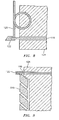
- dummy bar 116 Prior to forming strand 104 in mold 102, dummy bar 116 extends upward through the vertical portion of secondary cooling region 110. In this position, dummy bar 116 blocks the opening on the bottom of mold 102, as shown in Fig. 2 . In this manner, dummy bar 116 prevents metal from entering secondary cooling region 110 prematurely.
- dummy bar 116 retracts downward, freeing the way for strand 104 to enter secondary cooling region 110, as shown in Fig. 3 .
- Caster 100 can be configured in a variety of different arrangements, including vertical casting as opposed to casting from vertical to horizontal. Further, the exact arrangement of mold 102, secondary cooling region 110, sprayers 112, rollers 114, and dummy bar 116 can also be varied. Those of ordinary skill in the art will readily appreciate that any variation of caster 100 can be used.
- a temperature sensor is provided, disposed in the secondary cooling region.
- a means for biasing the temperature sensor in the direction of the strand of metal in response to receiving thermal energy from the strand of metal is also provided.
- caster 100 includes a sub-system in proximity to rollers 114, namely temperature measurement system 126, including temperature sensor 118 and member 120.
- a contact-type temperature sensor preferably makes positive thermal contact with the surface of strand 104.
- Means for biasing may be provided, for example in the form of heat sensitive biasing member 120, which takes advantage of the heat radiating from strand 104 by biasing sensor 118 toward the surface of strand 104 in response to the heat radiating therefrom.
- Sensor 118 and member 120 are configured and dimensioned so that when sensor 118 is biased toward strand 104 a positive thermal contact is achieved between strand 104 and sensor 118.
- member 120 includes an elongate, bimetallic strip in which the two metals have different coefficients of thermal expansion.
- the two metals, formed into strips are tightly bonded together into a single elongate strip, such as by welding a seam defined between the two metal strips around the edge of member 120.
- the heat radiating therefrom has the effect of deforming the bimetallic strip.
- Member 120 is arranged so that the movement from the deformation of the bimetallic element is in a direction toward strand 104.
- Sensor 118 is disposed near an end of member 120 so that the result of member 120 responding to heat from strand 104 is that sensor 118 is brought into thermal contact with the surface of strand 104. In this position it is possible for sensor 118 to continuously measure the surface temperature of strand 104 as strand 104 moves past sensor 118.
- member 120 undergoes reverse deformation, which relaxes the bimetallic element, and thereby withdraws temperature sensor 118 away from the plane defined by the path of the surface of strand 104.
- Sensor 118 and member 120 can remain in the retracted position until a new strand 104 arrives, heating the bimetallic element once again, deforming member 120 and extending sensor 118 back into a position in thermal contact with the new strand 104, and so forth.
- sensor 118 and member 120 to retract when there is no strand 104 present, and to extend toward the surface of a strand 104 when present, is particularly advantageous in the process of continuous casting.
- Dummy bar 116 extends up to mold 102, moving past rollers 114 and sensors 118, prior to each strand 104 being released through secondary cooling region 110. Dummy bar 116 then retracts moving down again past rollers 114 and sensors 118. If sensors 118 were always biased, by being spring loaded for example, toward the surface of strand 104, then in the absence of a strand 104 and dummy bar 116, sensors 118 would extend into the path of dummy bar 116.
- dummy bar 116 could easily shear temperature sensors 118 away from their mountings, or otherwise damage sensors 118, when dummy bar 116 moves past.
- Member 120 ensures that temperature sensor 118 extends into sensing position only when in the presence of strand 104. Temperature sensor 118 is therefore always clear from the path when dummy bar 116 passes and sensor 118 thus avoids being damaged thereby.
- a variety of other means for biasing are also envisioned besides bimetallic elements.
- Any device or mechanism capable of actuating movement of temperature sensor 118 toward strand 104 in response to heat from strand 104 can be used.
- a pneumatic or hydraulic actuator coupled with a temperature feedback sensor responsive to heat from strand 104 could be used as a means for biasing a temperature sensor toward strand 104.
- the simplicity of operation and maintenance of bimetallic elements make them a preferable means of biasing.
- Member 120 is shown as an elongate strip.
- the size of a bimetallic element can vary, however preferably the bimetallic element is about 0.1 inches thick.
- the bimetallic element can also be coiled, helical, or any other suitable shape, as shown by way of example as coiled member 220 and helical member 320 in Figs. 8 and 9 , respectively.
- Fig. 10 shows yet another suitable member 420 in the form of three bimetallic elements 422 attached end to end in an accordion arrangement to increase the amount of deflection within the given space. Any number of bimetallic elements could be used in such an accordion configuration.
- the bimetallic element can be made from a variety of combinations of metals.
- the bimetallic element of member 120 is made of a first portion that is 302 stainless steel and a second portion that is 410 stainless steel.
- first portion that is 302 stainless steel
- second portion that is 410 stainless steel.
- suitable materials that can be used.
- thermocouples there are a variety of types of temperature sensors 118 that can be used. Numerous suitable types of thermocouples are available, for example, from OMEGA Engineering, INC., One Omega Drive, Stamford, Connecticut 06907-0047 P.O. Box 4047. In a preferred embodiment, a type-K thermocouple is used as sensor 118. However, any suitable consumable or non-consumable thermocouple can be used. If thermocouples are used as sensors 118, preferably they are tip sensitive or grounded junction thermocouples.
- thermocouples other suitable temperature sensors 118 include thermistors, optic fiber thermometers, resistance temperature detectors (“RTD's”), temperature sensitive capacitors (“TSC's”), or any other sensors suited to measuring temperature in harsh environments like that in the continuous casting process. It is also possible for sensor 118 to be in the form of electrical leads, which when brought into physical contact with strand 104 can be used to measure electrical resistance of strand 104, and thereby infer the temperature of strand 104. It is also contemplated, since the junction of two dissimilar metals constitutes a thermocouple junction, that if a bimetallic element is used as member 120, the bimetallic element can itself double as a thermocouple.
- a bimetallic element properly configured, can serve as both means for biasing and as sensor 118. It is also possible to practice the invention using multiple temperature sensors as sensor 118, such as a thermopile or an array of thermistors. All of these varieties of temperature sensors, and their equivalents, can be used.
- temperature sensor 118 It is not necessary for temperature sensor 118 to come into direct physical contact with a moving strand 104, as shown in Figs. 4 and 5 . It is sufficient for sensor 118 to make positive thermal contact with strand 104. Moreover, in the context of temperature controlling a continuous casting process for example, it is not necessary for sensor 118 to provide exact temperatures of strand 104 itself, rather it is sufficient for sensor 118 to be responsive to changes in temperature in strand 104. In an alternative embodiment, shown by way of example and not limitation in Figs. 6 and 7 , wear bar 122 houses the sensitive portion of sensor 118. Wear bar 122 drags along the passing strand 104 and conducts heat from strand 104 into the sensitive portion of sensor 118.
- Wear bar 122 therefore protects the sensitive portion of sensor 118 from damage and wear that could arise from direct physical contact with strand 104, while also allowing meaningful temperature readings of strand 104 by placing sensor 118 in good thermal contact with strand 104.
- wear bar 122 is made of a nickel alloy, but any suitable wear resistant material that allows for thermal contact between sensor 118 and strand 104 can also be used.
- sensor 118 and member 120 can be integrated into bearing block 124 of roller 114. This location allows for temperature measurement system 126 to achieve good contact against strand 104 without adding undue bulk or otherwise interfering with the other components in secondary cooling region 110. While this arrangement is preferred, those of ordinary skill in the art will readily appreciate that other locations for mounting system 126 within secondary cooling region 110 may be used. Similarly, those of ordinary skill in the art will readily appreciate how to provide strain relief for any electrical leads that may be present for sensor 118. It is also preferred that member 120 and sensor 118 be integrated into bearing block 124 in such a way as to be replaceable while still in the operating position, thus reducing the amount of downtime required for changing out the components of system 126.
- caster 100 has multiple temperature measurement systems 126 located throughout secondary cooling region 110.
- Fig. 1 shows each roller 114 in secondary cooling region 110 having a system 126 associated therewith.
- Figs. 2 and 3 show different possible locations for systems 126, where only some of rollers 114 have systems 126 associated therewith. It is most preferable that multiple systems 126 be arranged in an array across the width and length of strand 104 in secondary cooling region 110. This arrangement allows for tight temperature control of strand 104, as it allows for more complete data on the surface temperature of strand 104. It is also contemplated that existing casters can be retrofitted with systems 126, or in the alternative new casters can be manufactured including integrated systems 126.
- non-contact-type temperature instruments must be used in secondary cooling region 110, such as infrared thermometers, radiometers, pyrometers or other optical and radiative instruments, so that the instrumentation can be offset from the path of dummy bar 116 and thus clear dummy bar 116 as it passes.
- the disadvantage of non-contact temperature measurement is that in general such techniques require clear visibility in order to provide meaningful surface temperature readings.
- clear visibility of strand 104 is virtually impossible due to the cooling sprays, steam, and other gasses present in proximity to strand 104.
- direct contact sensors provide much better readings. But traditionally direct contact sensors have had the disadvantage of needing to be replaced or repaired frequently because they risk being damaged each time dummy bar 116 passes.
- the only alternative has traditionally been to refrain from attempting any measurements within secondary cooling region 110, which gives the already stated disadvantage of deviation from ideal cooling curves with its accompanying loss in quality and risk of breakout, etc.
- the invention advances the state of the art of continuous casting because it allows for the benefits of direct contact-type temperature instrumentation without the destruction of the temperature sensors.
- the invention has the benefit of providing contact-type temperature measurements of strand 104 within secondary cooling region 110, which are more reliable and meaningful than non-contact measurements, while also providing the advantages that non-contact instruments have in clearing dummy bar 116.
- the invention also overcomes the disadvantages of traditional measurement techniques by avoiding the repeated damage to sensors 118 typical of traditional contact instruments in secondary cooling region 110, while avoiding the inaccuracy incurred by non-contact instruments in the steamy environment of a continuous caster. Meaningful temperature measurements in secondary cooling region 110 that require little or no maintenance solve a long existing need in the art because they present the possibility of tighter cooling control systems that will increase quality and reduce breakouts and down time over the state of the art.
- a temperature measurement system is also provided.
- the system includes a temperature sensor adapted and configured to receive thermal energy from a thermal energy source and means for biasing the temperature sensor in the direction of the thermal energy source in response to receiving thermal energy from the source.
- temperature measurement system 126 is provided having temperature sensor 118 and heat sensitive biasing member 120. Temperature measurement system 126 of the invention is described in detail above in the context of a continuous casting system. However, the temperature measurement system of the invention is not limited to use in a continuous casting system. A temperature measurement system in accordance with the invention can be used in any process or system in which temperature sensors need to be withdrawn from the sensing position while not in use in order to avoid damage or contamination, and extended into the sensing position when in use, wherein the movement between the extended and withdrawn positions is in response to a change in temperature.
- a temperature measurement system has been described including a temperature sensor and means for biasing the temperature sensor in the direction of a thermal energy source in response to receiving thermal energy from the source.
- a continuous casting system has been described including at least one temperature sensor disposed in the secondary cooling region and means for biasing the temperature sensor in the direction of the strand of metal in response to receiving thermal energy from the strand of metal.
Landscapes
- Physics & Mathematics (AREA)
- General Physics & Mathematics (AREA)
- Engineering & Computer Science (AREA)
- Mechanical Engineering (AREA)
- Continuous Casting (AREA)
- Measuring Temperature Or Quantity Of Heat (AREA)
- Radiation Pyrometers (AREA)
Claims (9)
- Temperaturmesssystem für das Überwachen der Temperatur eines Metallstranges (104) in einer Stranggießanlage (100), das aufweist:a) einen Temperatursensor (118), der ausgebildet und gestaltet ist, um Wärmeenergie vom Metallstrang (104) aufzunehmen; undb) einen im Allgemeinen länglichen Bimetallstreifen (120), der funktionell mit dem Temperatursensor (118) verbunden ist, wobei der Bimetallstreifen (120) gestaltet und ausgebildet ist, um den Temperatursensor (118) als Reaktion auf die vom Metallstrang (104) aufgenommene Wärmeenergie hin- und herzubewegen zwischen:i) einer ersten Position bei Nichtvorhandensein eines Metallstranges (104), in der der Bimetallstreifen (120) den Temperatursensor (118) in eine Position zurückzieht, die ein passierender Anfahrstrang (116) ohne Beschädigung am Sensor (118) freigibt; undii) einer zweiten Position, in Gegenwart des Metallstranges (104), in der der Temperatursensor (118) in Wärmekontakt mit dem Metallstrang (104) ist.
- Temperaturmesssystem nach Anspruch 1, bei dem der Temperatursensor (118) ein Thermoelement umfasst.
- Temperaturmesssystem nach Anspruch 2, bei dem das Thermoelement ein Typ ist, der ausgewählt wird aus der Liste, die besteht aus: einem spitzenempfindlichen; einem mit geerdeten Übergang; einem verbrauchbaren; einem nicht verbrauchbaren; und einer Thermosäule.
- Temperaturmesssystem nach Anspruch 1, bei dem der Temperatursensor (118) mindestens einen Temperatursensor umfasst, der ausgewählt wird aus der Liste, die besteht aus: einem Thermistor; einem Lichtwellenleiterthermometer; einem RTD; einem TSC; und einem Satz Elektroden, die geeicht sind, um die Temperatur auf der Basis des elektrischen Widerstandes zwischen den Elektroden abzuleiten.
- Temperaturmesssystem nach Anspruch 1, bei dem der Temperatursensor (118) mit dem Metallstrang (104) durch eine Schutzschicht (122) in Wärmekontakt ist, während er sich in der zweiten Position befindet.
- Temperaturmesssystem nach Anspruch 5, bei dem die Schutzschicht (122) ein Verschleißstab ist, der am Bimetallstreifen (120) befestigt ist.
- Verfahren zur Messung der Temperatur eines Körpers (104), wobei das Verfahren die folgenden Schritte aufweist:a) Bereitstellen eines Temperatursensors (118) mit einem wärmeempfindlichen Vorspannelement (120), das damit verbunden ist;b) Ausziehen des wärmeempfindlichen Vorspannelementes (120) von einer ersten Position, in der der Temperatursensor (118) vom Körper (104) weg verschoben wird, zu einer zweiten Position, in der sich der Temperatursensor (118) in unmittelbarer Nähe zum Körper (104) als Reaktion auf die vom Körper (104) aufgenommene Wärme befindet;c) Messen der Temperatur des Körpers (104) mit dem Temperatursensor (118);d) Entfernen des Körpers (104) aus der unmittelbaren Nähe zum Temperatursensor (118) und dem wärmeempfindlichen Vorspannelement (120); unde) Zurückziehen des wärmeempfindlichen Vorspannelementes (120) aus der zweiten Position zurück in die erste Position als Reaktion auf das Nichtvorhandensein der Nähe zum Körper (104),wobei der Körper (104) ein Metallstrang in einer Stranggießanlage (100) ist, und wobei der Schritt des Zurückziehens das Zurückziehen des Temperatursensors (118) zu einer Stelle umfasst, die frei von einem Anfahrstrang (116) ist, der beweglich innerhalb der Stranggießanlage (100) angeordnet ist, wobei der Anfahrstrang (116) ausgebildet und gestaltet ist, um dem Metallstrang (104) in der ausgezogenen Position zu entsprechen, wenn ein neuer Metallstrang anfangs in der Anlage hergestellt wird, wobei der Anfahrstrang (116) außerdem ausgebildet und gestaltet ist, um sich zurückzuziehen, während sich der Strang durch das System bewegt.
- Verfahren nach Anspruch 7, bei dem der Schritt des Ausziehens das Ausziehen bis zu einer zweiten Position umfasst, in der der Temperatursensor (118) körperlich eine Oberfläche des Körpers (104) kontaktiert.
- Verfahren nach Anspruch 7 oder 8, bei dem der Schritt des Messens das Schützen des Temperatursensors (118) vor einem direkten körperlichen Kontakt mit dem Metallstrang durch Messen der Temperatur des Körpers (104) mit dem Temperatursensor umfasst, der innerhalb eines Verschleißstabes (122) angeordnet ist, wobei der Verschleißstab (122) in direktem körperlichem Kontakt mit dem Metallstrang (104) ist.
Priority Applications (1)
| Application Number | Priority Date | Filing Date | Title |
|---|---|---|---|
| EP10015707.2A EP2354774B1 (de) | 2007-02-21 | 2008-02-12 | Temperaturmesssystem |
Applications Claiming Priority (1)
| Application Number | Priority Date | Filing Date | Title |
|---|---|---|---|
| US11/709,070 US7549797B2 (en) | 2007-02-21 | 2007-02-21 | Temperature measurement system |
Related Child Applications (2)
| Application Number | Title | Priority Date | Filing Date |
|---|---|---|---|
| EP10015707.2A Division EP2354774B1 (de) | 2007-02-21 | 2008-02-12 | Temperaturmesssystem |
| EP10015707.2 Division-Into | 2010-12-16 |
Publications (3)
| Publication Number | Publication Date |
|---|---|
| EP1962071A2 EP1962071A2 (de) | 2008-08-27 |
| EP1962071A3 EP1962071A3 (de) | 2009-07-29 |
| EP1962071B1 true EP1962071B1 (de) | 2012-04-25 |
Family
ID=39512831
Family Applications (2)
| Application Number | Title | Priority Date | Filing Date |
|---|---|---|---|
| EP10015707.2A Not-in-force EP2354774B1 (de) | 2007-02-21 | 2008-02-12 | Temperaturmesssystem |
| EP08002565A Not-in-force EP1962071B1 (de) | 2007-02-21 | 2008-02-12 | Temperaturmesssystem |
Family Applications Before (1)
| Application Number | Title | Priority Date | Filing Date |
|---|---|---|---|
| EP10015707.2A Not-in-force EP2354774B1 (de) | 2007-02-21 | 2008-02-12 | Temperaturmesssystem |
Country Status (5)
| Country | Link |
|---|---|
| US (1) | US7549797B2 (de) |
| EP (2) | EP2354774B1 (de) |
| JP (2) | JP2008203260A (de) |
| AT (1) | ATE555371T1 (de) |
| ES (1) | ES2384809T3 (de) |
Families Citing this family (16)
| Publication number | Priority date | Publication date | Assignee | Title |
|---|---|---|---|---|
| JP4760590B2 (ja) * | 2006-07-26 | 2011-08-31 | 株式会社デンソー | 温度検出素子 |
| US7549792B2 (en) * | 2006-10-06 | 2009-06-23 | Covidien Ag | Electronic thermometer with selectable modes |
| BRPI0714891B1 (pt) * | 2007-10-24 | 2018-07-24 | Shenyang Taihe Metallurgy Measurement & Control Technology Co. Ltd. | Método e dispositivo de medição da temperatura superficial de tarugos e placas de fundição contínua |
| JP2010052851A (ja) * | 2008-08-26 | 2010-03-11 | Kyocera Mita Corp | 温風発生装置、給紙装置及びこれらを備えた画像形成装置 |
| KR101149144B1 (ko) * | 2009-07-24 | 2012-06-01 | 현대제철 주식회사 | 압연재의 온도 측정 장치 |
| BR112013020392B1 (pt) * | 2011-02-14 | 2020-05-12 | Nippon Steel Corporation | Dispositivo de medição de temperatura de superfície de placa lingotada usado em máquina de lingotamento contínuo |
| KR101376565B1 (ko) * | 2011-12-15 | 2014-04-02 | (주)포스코 | 연속 소둔라인 급냉대의 스트립 온도제어 방법 및 장치 |
| AU2013310149B2 (en) * | 2012-08-28 | 2015-06-11 | Nippon Steel Corporation | Method and Apparatus for Measuring Surface Temperature of Cast Slab |
| US9682334B2 (en) | 2013-03-13 | 2017-06-20 | Ecolab Usa Inc. | Solid water separation to sample spray water from a continuous caster |
| FR3048081A1 (fr) * | 2016-02-24 | 2017-08-25 | Univ D'artois | Fluxmetre thermique |
| DE102016107168B4 (de) | 2016-04-18 | 2025-05-22 | Carl Zeiss Industrielle Messtechnik Gmbh | Verfahren zum Abkühlen von Werkstücken |
| US10310462B2 (en) | 2016-05-05 | 2019-06-04 | Honeywell International Inc. | System and apparatus for sustaining process temperature measurement for RTD lead wire break |
| CN109014106B (zh) * | 2017-06-12 | 2020-07-21 | 上海梅山钢铁股份有限公司 | 减少板坯连铸尾坯精整量和提高坯尾温度的封顶方法 |
| CN112413616B (zh) * | 2020-10-14 | 2022-11-18 | 湖北工业大学 | 一种高温锅炉自动温度场测量吹灰系统 |
| CN116944440A (zh) * | 2022-04-13 | 2023-10-27 | 斯凯孚公司 | 集成光学传感器的导向辊以及连铸机 |
| TWI880722B (zh) * | 2023-05-08 | 2025-04-11 | 美商賀利氏科納米北美有限責任公司 | 自動化高溫計追蹤 |
Citations (1)
| Publication number | Priority date | Publication date | Assignee | Title |
|---|---|---|---|---|
| US4787438A (en) * | 1986-02-27 | 1988-11-29 | Sms Schloemann-Siemag, A.G. | Method and apparatus for continuously casting metal |
Family Cites Families (51)
| Publication number | Priority date | Publication date | Assignee | Title |
|---|---|---|---|---|
| US3015234A (en) * | 1958-04-14 | 1962-01-02 | Gay Sales Co | Bimetallic mounting |
| DE1408481A1 (de) * | 1959-09-15 | 1968-10-03 | Gerdts Gustav F Kg | Bimetall-Ausdehnungskoerper |
| US3263502A (en) * | 1964-01-21 | 1966-08-02 | Redwood L Springfield | Multiple thermocouple support |
| US3478808A (en) * | 1964-10-08 | 1969-11-18 | Bunker Ramo | Method of continuously casting steel |
| DE1813330C3 (de) * | 1968-12-07 | 1978-06-01 | Demag Ag, 4100 Duisburg | Einrichtung zum fortlaufenden Messen der Temperatur an Metallsträngen, insbesondere beim Stranggießen von Stahl |
| US3559485A (en) | 1969-02-25 | 1971-02-02 | Bloom Eng Co Inc | Method and apparatus for temperature measurement in a metallurgical furnace |
| CH552424A (de) | 1972-09-06 | 1974-08-15 | Concast Ag | Verfahren zum steuern der kuehlung eines aus einer durchlaufkokille austretenden stranges und vorrichtung zur durchfuehrung dieses verfahrens. |
| US4009750A (en) | 1972-09-06 | 1977-03-01 | Concast Ag | Apparatus for controlling the cooling of a strand emanating from a continuous casting mold |
| US4073332A (en) | 1974-09-26 | 1978-02-14 | Centre De Recherches Metallurgiques Centrum Voor Research In De Metallurgie | Method of controlling continuous casting of a metal |
| BE822744A (fr) | 1974-11-28 | 1975-03-14 | Procede pour la mesure de la temperature notamment d'un lingot de metal. | |
| JPS593740B2 (ja) | 1975-07-30 | 1984-01-25 | 日立化成工業株式会社 | 凹凸表面に感光層の形成された固体板の製造法 |
| BE884195R (fr) | 1978-01-03 | 1981-01-05 | Centre Rech Metallurgique | Perfectionnements aux procedes de mesure de la temperature, specialement celle d'un lingot de metal |
| JPS5440676A (en) * | 1977-09-06 | 1979-03-30 | Iida Sankyo | Set temperature detector |
| BE862611A (fr) | 1978-01-03 | 1978-07-03 | Centre Rech Metallurgique | Perfectionnements aux procedes de mesure de la temperature, specialement celle d'un lingot de metal. |
| DE3017044C2 (de) * | 1980-05-03 | 1983-08-18 | G. Rau GmbH & Co, 7530 Pforzheim | Thermobimetall mit hoher Anwendungsgrenze sowie Herstellungsverfahren hierzu |
| JPS58119452A (ja) * | 1982-01-09 | 1983-07-15 | Kawasaki Steel Corp | 連続鋳造における鋳片表面温度の制御方法 |
| JPS58199612A (ja) | 1982-05-17 | 1983-11-21 | Toshiba Corp | 注水バンク制御方法 |
| DE3321028A1 (de) | 1982-06-17 | 1983-12-22 | Smiths Industries Public Ltd. Co., London | Optisches bauteil |
| JPS6015059A (ja) | 1983-07-06 | 1985-01-25 | Nippon Kokan Kk <Nkk> | スラブの温度分布測定装置 |
| US4666297A (en) | 1985-11-14 | 1987-05-19 | United Technologies Corporation | Dual spectra optical pyrometer having an air pressure sensitive shutter |
| US4836689A (en) | 1986-02-27 | 1989-06-06 | Rosemount Inc. | Asymmetric purge air system for cleaning a lens |
| US4786188A (en) | 1986-02-27 | 1988-11-22 | Rosemont Inc. | Purge air system for a combustion instrument |
| JPS62230464A (ja) | 1986-03-31 | 1987-10-09 | Sumitomo Metal Ind Ltd | 連続鋳造における鋳片表面温度測定装置 |
| US4707148A (en) * | 1986-04-02 | 1987-11-17 | Thermo Electric Instruments | Temperature sensing device |
| US4699202A (en) | 1986-10-02 | 1987-10-13 | Bethlehem Steel Corporation | System and method for controlling secondary spray cooling in continuous casting |
| JPS63235055A (ja) | 1987-03-24 | 1988-09-30 | Sumitomo Metal Ind Ltd | 連続鋳造鋳片の表面温度制御方法 |
| DE8802281U1 (de) * | 1988-02-22 | 1988-05-19 | Siemens AG, 1000 Berlin und 8000 München | Direkt beheizter Bimetallstreifen |
| DE3827254A1 (de) * | 1988-08-11 | 1990-02-15 | Vdo Schindling | Temperaturschalter |
| US5146244A (en) | 1990-01-23 | 1992-09-08 | Rosemount Inc. | Window purging system for a combustion instrument |
| JPH0654256B2 (ja) | 1990-06-27 | 1994-07-20 | 株式会社寺岡精工 | 計数秤 |
| JPH0487436U (de) * | 1990-11-30 | 1992-07-29 | ||
| US5125739A (en) | 1991-01-14 | 1992-06-30 | United Technologies Corporation | Triple spectral area pyrometer |
| JPH04339555A (ja) | 1991-05-15 | 1992-11-26 | Sumitomo Metal Ind Ltd | 連続鋳造鋳片の表面温度制御方法 |
| US5472145A (en) | 1994-04-14 | 1995-12-05 | Delavan Inc. | Straight stream nozzle |
| JP3193253B2 (ja) | 1995-01-17 | 2001-07-30 | 東海ゴム工業株式会社 | 流体封入式防振ブッシュ |
| JPH08267207A (ja) | 1995-03-30 | 1996-10-15 | Kawasaki Steel Corp | 連続鋳造方法 |
| JP3445405B2 (ja) * | 1995-04-21 | 2003-09-08 | 住友特殊金属株式会社 | 合金鋳片の製造方法と合金鋳片製造用スクレーパー |
| US6264767B1 (en) | 1995-06-07 | 2001-07-24 | Ipsco Enterprises Inc. | Method of producing martensite-or bainite-rich steel using steckel mill and controlled cooling |
| US6012507A (en) * | 1997-06-12 | 2000-01-11 | Alcan International Limited | Apparatus and method for measuring the temperature of a moving surface |
| CA2332933C (en) | 1998-07-10 | 2007-11-06 | Ipsco Inc. | Method and apparatus for producing martensite- or bainite-rich steel using steckel mill and controlled cooling |
| JP2000310570A (ja) * | 1999-04-28 | 2000-11-07 | Mitsui Mining & Smelting Co Ltd | 炊事具の温度検出具 |
| US6688534B2 (en) | 2001-03-07 | 2004-02-10 | Delavan Inc | Air assist fuel nozzle |
| WO2003024611A1 (en) | 2001-09-20 | 2003-03-27 | Delavan Inc. | Low pressure spray nozzle |
| JP3803066B2 (ja) * | 2002-02-05 | 2006-08-02 | 安立計器株式会社 | 接触式温度センサ |
| US6789602B2 (en) | 2002-02-11 | 2004-09-14 | Commonwealth Industries, Inc. | Process for producing aluminum sheet product having controlled recrystallization |
| US6863228B2 (en) | 2002-09-30 | 2005-03-08 | Delavan Inc. | Discrete jet atomizer |
| RU2236325C1 (ru) | 2003-01-22 | 2004-09-20 | Открытое акционерное общество "Северсталь" | Устройство для вторичного охлаждения непрерывнолитого слитка |
| JP2004243390A (ja) | 2003-02-14 | 2004-09-02 | Sanyo Special Steel Co Ltd | 連続鋳造における2次帯での冷却方法 |
| US7334413B2 (en) | 2004-05-07 | 2008-02-26 | Rosemount Aerospace Inc. | Apparatus, system and method for observing combustion conditions in a gas turbine engine |
| US7484369B2 (en) | 2004-05-07 | 2009-02-03 | Rosemount Aerospace Inc. | Apparatus for observing combustion conditions in a gas turbine engine |
| JP4833090B2 (ja) * | 2007-01-15 | 2011-12-07 | 株式会社テイエルブイ | 温度センサ |
-
2007
- 2007-02-21 US US11/709,070 patent/US7549797B2/en not_active Expired - Fee Related
-
2008
- 2008-02-12 AT AT08002565T patent/ATE555371T1/de active
- 2008-02-12 ES ES08002565T patent/ES2384809T3/es active Active
- 2008-02-12 EP EP10015707.2A patent/EP2354774B1/de not_active Not-in-force
- 2008-02-12 EP EP08002565A patent/EP1962071B1/de not_active Not-in-force
- 2008-02-15 JP JP2008033924A patent/JP2008203260A/ja not_active Ceased
-
2012
- 2012-05-10 JP JP2012108456A patent/JP2012183587A/ja active Pending
Patent Citations (1)
| Publication number | Priority date | Publication date | Assignee | Title |
|---|---|---|---|---|
| US4787438A (en) * | 1986-02-27 | 1988-11-29 | Sms Schloemann-Siemag, A.G. | Method and apparatus for continuously casting metal |
Also Published As
| Publication number | Publication date |
|---|---|
| ES2384809T3 (es) | 2012-07-12 |
| US20080198900A1 (en) | 2008-08-21 |
| EP1962071A2 (de) | 2008-08-27 |
| EP2354774A3 (de) | 2011-12-28 |
| EP2354774B1 (de) | 2014-07-30 |
| EP2354774A2 (de) | 2011-08-10 |
| JP2008203260A (ja) | 2008-09-04 |
| US7549797B2 (en) | 2009-06-23 |
| EP1962071A3 (de) | 2009-07-29 |
| ATE555371T1 (de) | 2012-05-15 |
| JP2012183587A (ja) | 2012-09-27 |
Similar Documents
| Publication | Publication Date | Title |
|---|---|---|
| EP1962071B1 (de) | Temperaturmesssystem | |
| US3921697A (en) | Method and apparatus for controlling the operating conditions in continuous metal casting machines having a revolving endless casting belt | |
| EP3377238B1 (de) | Giessverfahren für bleichstreifen mit balligkeitssteuerung | |
| US3864973A (en) | Method and apparatus for determining the operating conditions in continuous metal casting machines of the type having a revolving endless casting belt | |
| EP3753648B1 (de) | Verfahren und vorrichtung zur steuerung einer variablen hüllendicke eines gussstreifens | |
| JP2017536242A (ja) | クラウン制御を備える金属ストリップをキャスティングする方法 | |
| KR20200127034A (ko) | 금속용 연속 주조 잉곳 주형, 연속 금속 주조기에서의 브레이크아웃 감지 시스템 및 방법 | |
| WO2006130941A1 (en) | Device for continuous temperature measurement of molten steel in the undish using optical fiber and infra-red pyrometer | |
| US11148193B2 (en) | Method for casting metal strip with edge control | |
| KR102365633B1 (ko) | 크라운 제어를 이용하여 금속 스트립을 주조하기 위한 주조 롤 및 방법 | |
| US20110067835A1 (en) | Method and apparatus for controlling strip temperature rebound in cast strip | |
| EP0259876B1 (de) | Verfahren zur automatischen Füllstandskontrolle für Doppelband-Stranggussmaschinen | |
| JPH0567893B2 (de) | ||
| KR101755402B1 (ko) | 탕면 가시화 장치 | |
| US20100132912A1 (en) | Strip casting apparatus with improved side dam | |
| JPS6030565A (ja) | 加熱鋳型式連続鋳造法における鋳塊表面形状の安定法 | |
| JP5621623B2 (ja) | 連続鋳造機におけるロールの冷却方法、冷却装置及び鋳片支持ロール | |
| Usher | Continuous measurement of liquid steel temperature in the tundish | |
| JPH0555216B2 (de) | ||
| JPH0461737B2 (de) | ||
| BR112019026570B1 (pt) | Sistemas de controle de cilindro de lingotamento com controle de circunferencial ajustável para o uso em um lingotador de cilindros gêmeos para produzir metal em tira lingotada | |
| KR20110006947A (ko) | 소재의 온도 측정 장치 |
Legal Events
| Date | Code | Title | Description |
|---|---|---|---|
| PUAI | Public reference made under article 153(3) epc to a published international application that has entered the european phase |
Free format text: ORIGINAL CODE: 0009012 |
|
| AK | Designated contracting states |
Kind code of ref document: A2 Designated state(s): AT BE BG CH CY CZ DE DK EE ES FI FR GB GR HR HU IE IS IT LI LT LU LV MC MT NL NO PL PT RO SE SI SK TR |
|
| AX | Request for extension of the european patent |
Extension state: AL BA MK RS |
|
| PUAL | Search report despatched |
Free format text: ORIGINAL CODE: 0009013 |
|
| AK | Designated contracting states |
Kind code of ref document: A3 Designated state(s): AT BE BG CH CY CZ DE DK EE ES FI FR GB GR HR HU IE IS IT LI LT LU LV MC MT NL NO PL PT RO SE SI SK TR |
|
| AX | Request for extension of the european patent |
Extension state: AL BA MK RS |
|
| 17P | Request for examination filed |
Effective date: 20091118 |
|
| 17Q | First examination report despatched |
Effective date: 20091218 |
|
| AKX | Designation fees paid |
Designated state(s): AT BE BG CH CY CZ DE DK EE ES FI FR GB GR HR HU IE IS IT LI LT LU LV MC MT NL NO PL PT RO SE SI SK TR |
|
| 17Q | First examination report despatched |
Effective date: 20100326 |
|
| GRAP | Despatch of communication of intention to grant a patent |
Free format text: ORIGINAL CODE: EPIDOSNIGR1 |
|
| GRAS | Grant fee paid |
Free format text: ORIGINAL CODE: EPIDOSNIGR3 |
|
| GRAA | (expected) grant |
Free format text: ORIGINAL CODE: 0009210 |
|
| AK | Designated contracting states |
Kind code of ref document: B1 Designated state(s): AT BE BG CH CY CZ DE DK EE ES FI FR GB GR HR HU IE IS IT LI LT LU LV MC MT NL NO PL PT RO SE SI SK TR |
|
| REG | Reference to a national code |
Ref country code: GB Ref legal event code: FG4D |
|
| REG | Reference to a national code |
Ref country code: CH Ref legal event code: EP |
|
| REG | Reference to a national code |
Ref country code: AT Ref legal event code: REF Ref document number: 555371 Country of ref document: AT Kind code of ref document: T Effective date: 20120515 |
|
| REG | Reference to a national code |
Ref country code: IE Ref legal event code: FG4D |
|
| REG | Reference to a national code |
Ref country code: DE Ref legal event code: R096 Ref document number: 602008015108 Country of ref document: DE Effective date: 20120621 |
|
| REG | Reference to a national code |
Ref country code: CH Ref legal event code: NV Representative=s name: MARKS & CLERK (LUXEMBOURG) LLP |
|
| REG | Reference to a national code |
Ref country code: ES Ref legal event code: FG2A Ref document number: 2384809 Country of ref document: ES Kind code of ref document: T3 Effective date: 20120712 |
|
| REG | Reference to a national code |
Ref country code: SE Ref legal event code: TRGR |
|
| REG | Reference to a national code |
Ref country code: NL Ref legal event code: VDEP Effective date: 20120425 |
|
| REG | Reference to a national code |
Ref country code: AT Ref legal event code: MK05 Ref document number: 555371 Country of ref document: AT Kind code of ref document: T Effective date: 20120425 |
|
| LTIE | Lt: invalidation of european patent or patent extension |
Effective date: 20120425 |
|
| PG25 | Lapsed in a contracting state [announced via postgrant information from national office to epo] |
Ref country code: LT Free format text: LAPSE BECAUSE OF FAILURE TO SUBMIT A TRANSLATION OF THE DESCRIPTION OR TO PAY THE FEE WITHIN THE PRESCRIBED TIME-LIMIT Effective date: 20120425 Ref country code: IS Free format text: LAPSE BECAUSE OF FAILURE TO SUBMIT A TRANSLATION OF THE DESCRIPTION OR TO PAY THE FEE WITHIN THE PRESCRIBED TIME-LIMIT Effective date: 20120825 Ref country code: FI Free format text: LAPSE BECAUSE OF FAILURE TO SUBMIT A TRANSLATION OF THE DESCRIPTION OR TO PAY THE FEE WITHIN THE PRESCRIBED TIME-LIMIT Effective date: 20120425 Ref country code: CY Free format text: LAPSE BECAUSE OF FAILURE TO SUBMIT A TRANSLATION OF THE DESCRIPTION OR TO PAY THE FEE WITHIN THE PRESCRIBED TIME-LIMIT Effective date: 20120425 Ref country code: PL Free format text: LAPSE BECAUSE OF FAILURE TO SUBMIT A TRANSLATION OF THE DESCRIPTION OR TO PAY THE FEE WITHIN THE PRESCRIBED TIME-LIMIT Effective date: 20120425 Ref country code: NO Free format text: LAPSE BECAUSE OF FAILURE TO SUBMIT A TRANSLATION OF THE DESCRIPTION OR TO PAY THE FEE WITHIN THE PRESCRIBED TIME-LIMIT Effective date: 20120725 |
|
| PG25 | Lapsed in a contracting state [announced via postgrant information from national office to epo] |
Ref country code: HR Free format text: LAPSE BECAUSE OF FAILURE TO SUBMIT A TRANSLATION OF THE DESCRIPTION OR TO PAY THE FEE WITHIN THE PRESCRIBED TIME-LIMIT Effective date: 20120425 Ref country code: PT Free format text: LAPSE BECAUSE OF FAILURE TO SUBMIT A TRANSLATION OF THE DESCRIPTION OR TO PAY THE FEE WITHIN THE PRESCRIBED TIME-LIMIT Effective date: 20120827 Ref country code: LV Free format text: LAPSE BECAUSE OF FAILURE TO SUBMIT A TRANSLATION OF THE DESCRIPTION OR TO PAY THE FEE WITHIN THE PRESCRIBED TIME-LIMIT Effective date: 20120425 Ref country code: SI Free format text: LAPSE BECAUSE OF FAILURE TO SUBMIT A TRANSLATION OF THE DESCRIPTION OR TO PAY THE FEE WITHIN THE PRESCRIBED TIME-LIMIT Effective date: 20120425 Ref country code: GR Free format text: LAPSE BECAUSE OF FAILURE TO SUBMIT A TRANSLATION OF THE DESCRIPTION OR TO PAY THE FEE WITHIN THE PRESCRIBED TIME-LIMIT Effective date: 20120726 |
|
| PG25 | Lapsed in a contracting state [announced via postgrant information from national office to epo] |
Ref country code: BE Free format text: LAPSE BECAUSE OF FAILURE TO SUBMIT A TRANSLATION OF THE DESCRIPTION OR TO PAY THE FEE WITHIN THE PRESCRIBED TIME-LIMIT Effective date: 20120425 |
|
| PG25 | Lapsed in a contracting state [announced via postgrant information from national office to epo] |
Ref country code: EE Free format text: LAPSE BECAUSE OF FAILURE TO SUBMIT A TRANSLATION OF THE DESCRIPTION OR TO PAY THE FEE WITHIN THE PRESCRIBED TIME-LIMIT Effective date: 20120425 Ref country code: RO Free format text: LAPSE BECAUSE OF FAILURE TO SUBMIT A TRANSLATION OF THE DESCRIPTION OR TO PAY THE FEE WITHIN THE PRESCRIBED TIME-LIMIT Effective date: 20120425 Ref country code: DK Free format text: LAPSE BECAUSE OF FAILURE TO SUBMIT A TRANSLATION OF THE DESCRIPTION OR TO PAY THE FEE WITHIN THE PRESCRIBED TIME-LIMIT Effective date: 20120425 Ref country code: CZ Free format text: LAPSE BECAUSE OF FAILURE TO SUBMIT A TRANSLATION OF THE DESCRIPTION OR TO PAY THE FEE WITHIN THE PRESCRIBED TIME-LIMIT Effective date: 20120425 Ref country code: AT Free format text: LAPSE BECAUSE OF FAILURE TO SUBMIT A TRANSLATION OF THE DESCRIPTION OR TO PAY THE FEE WITHIN THE PRESCRIBED TIME-LIMIT Effective date: 20120425 Ref country code: NL Free format text: LAPSE BECAUSE OF FAILURE TO SUBMIT A TRANSLATION OF THE DESCRIPTION OR TO PAY THE FEE WITHIN THE PRESCRIBED TIME-LIMIT Effective date: 20120425 Ref country code: SK Free format text: LAPSE BECAUSE OF FAILURE TO SUBMIT A TRANSLATION OF THE DESCRIPTION OR TO PAY THE FEE WITHIN THE PRESCRIBED TIME-LIMIT Effective date: 20120425 |
|
| PLBE | No opposition filed within time limit |
Free format text: ORIGINAL CODE: 0009261 |
|
| STAA | Information on the status of an ep patent application or granted ep patent |
Free format text: STATUS: NO OPPOSITION FILED WITHIN TIME LIMIT |
|
| 26N | No opposition filed |
Effective date: 20130128 |
|
| PGFP | Annual fee paid to national office [announced via postgrant information from national office to epo] |
Ref country code: CH Payment date: 20130225 Year of fee payment: 6 Ref country code: ES Payment date: 20130226 Year of fee payment: 6 Ref country code: SE Payment date: 20130227 Year of fee payment: 6 |
|
| REG | Reference to a national code |
Ref country code: DE Ref legal event code: R097 Ref document number: 602008015108 Country of ref document: DE Effective date: 20130128 |
|
| PG25 | Lapsed in a contracting state [announced via postgrant information from national office to epo] |
Ref country code: BG Free format text: LAPSE BECAUSE OF FAILURE TO SUBMIT A TRANSLATION OF THE DESCRIPTION OR TO PAY THE FEE WITHIN THE PRESCRIBED TIME-LIMIT Effective date: 20120725 |
|
| PG25 | Lapsed in a contracting state [announced via postgrant information from national office to epo] |
Ref country code: MC Free format text: LAPSE BECAUSE OF NON-PAYMENT OF DUE FEES Effective date: 20130228 |
|
| REG | Reference to a national code |
Ref country code: IE Ref legal event code: MM4A |
|
| PG25 | Lapsed in a contracting state [announced via postgrant information from national office to epo] |
Ref country code: IE Free format text: LAPSE BECAUSE OF NON-PAYMENT OF DUE FEES Effective date: 20130212 |
|
| PG25 | Lapsed in a contracting state [announced via postgrant information from national office to epo] |
Ref country code: MT Free format text: LAPSE BECAUSE OF FAILURE TO SUBMIT A TRANSLATION OF THE DESCRIPTION OR TO PAY THE FEE WITHIN THE PRESCRIBED TIME-LIMIT Effective date: 20120425 |
|
| REG | Reference to a national code |
Ref country code: SE Ref legal event code: EUG Ref country code: CH Ref legal event code: PL |
|
| PG25 | Lapsed in a contracting state [announced via postgrant information from national office to epo] |
Ref country code: CH Free format text: LAPSE BECAUSE OF NON-PAYMENT OF DUE FEES Effective date: 20140228 Ref country code: LI Free format text: LAPSE BECAUSE OF NON-PAYMENT OF DUE FEES Effective date: 20140228 |
|
| PG25 | Lapsed in a contracting state [announced via postgrant information from national office to epo] |
Ref country code: SE Free format text: LAPSE BECAUSE OF NON-PAYMENT OF DUE FEES Effective date: 20140213 |
|
| REG | Reference to a national code |
Ref country code: FR Ref legal event code: PLFP Year of fee payment: 8 |
|
| PGFP | Annual fee paid to national office [announced via postgrant information from national office to epo] |
Ref country code: DE Payment date: 20150203 Year of fee payment: 8 |
|
| PGFP | Annual fee paid to national office [announced via postgrant information from national office to epo] |
Ref country code: GB Payment date: 20150211 Year of fee payment: 8 Ref country code: FR Payment date: 20150210 Year of fee payment: 8 |
|
| PG25 | Lapsed in a contracting state [announced via postgrant information from national office to epo] |
Ref country code: TR Free format text: LAPSE BECAUSE OF FAILURE TO SUBMIT A TRANSLATION OF THE DESCRIPTION OR TO PAY THE FEE WITHIN THE PRESCRIBED TIME-LIMIT Effective date: 20120425 |
|
| REG | Reference to a national code |
Ref country code: ES Ref legal event code: FD2A Effective date: 20150703 |
|
| PG25 | Lapsed in a contracting state [announced via postgrant information from national office to epo] |
Ref country code: HU Free format text: LAPSE BECAUSE OF FAILURE TO SUBMIT A TRANSLATION OF THE DESCRIPTION OR TO PAY THE FEE WITHIN THE PRESCRIBED TIME-LIMIT; INVALID AB INITIO Effective date: 20080212 Ref country code: LU Free format text: LAPSE BECAUSE OF NON-PAYMENT OF DUE FEES Effective date: 20130212 Ref country code: ES Free format text: LAPSE BECAUSE OF NON-PAYMENT OF DUE FEES Effective date: 20140213 |
|
| PG25 | Lapsed in a contracting state [announced via postgrant information from national office to epo] |
Ref country code: IT Free format text: LAPSE BECAUSE OF NON-PAYMENT OF DUE FEES Effective date: 20140212 |
|
| REG | Reference to a national code |
Ref country code: DE Ref legal event code: R119 Ref document number: 602008015108 Country of ref document: DE |
|
| GBPC | Gb: european patent ceased through non-payment of renewal fee |
Effective date: 20160212 |
|
| REG | Reference to a national code |
Ref country code: FR Ref legal event code: ST Effective date: 20161028 |
|
| PG25 | Lapsed in a contracting state [announced via postgrant information from national office to epo] |
Ref country code: FR Free format text: LAPSE BECAUSE OF NON-PAYMENT OF DUE FEES Effective date: 20160229 Ref country code: GB Free format text: LAPSE BECAUSE OF NON-PAYMENT OF DUE FEES Effective date: 20160212 Ref country code: DE Free format text: LAPSE BECAUSE OF NON-PAYMENT OF DUE FEES Effective date: 20160901 |