EP1962016A2 - Plaque de brûleur - Google Patents
Plaque de brûleur Download PDFInfo
- Publication number
- EP1962016A2 EP1962016A2 EP20080101726 EP08101726A EP1962016A2 EP 1962016 A2 EP1962016 A2 EP 1962016A2 EP 20080101726 EP20080101726 EP 20080101726 EP 08101726 A EP08101726 A EP 08101726A EP 1962016 A2 EP1962016 A2 EP 1962016A2
- Authority
- EP
- European Patent Office
- Prior art keywords
- combustion region
- burner plate
- combustion
- plate according
- burner
- Prior art date
- Legal status (The legal status is an assumption and is not a legal conclusion. Google has not performed a legal analysis and makes no representation as to the accuracy of the status listed.)
- Withdrawn
Links
Images

Classifications
-
- F—MECHANICAL ENGINEERING; LIGHTING; HEATING; WEAPONS; BLASTING
- F23—COMBUSTION APPARATUS; COMBUSTION PROCESSES
- F23D—BURNERS
- F23D14/00—Burners for combustion of a gas, e.g. of a gas stored under pressure as a liquid
- F23D14/46—Details
- F23D14/48—Nozzles
- F23D14/58—Nozzles characterised by the shape or arrangement of the outlet or outlets from the nozzle, e.g. of annular configuration
-
- F—MECHANICAL ENGINEERING; LIGHTING; HEATING; WEAPONS; BLASTING
- F23—COMBUSTION APPARATUS; COMBUSTION PROCESSES
- F23D—BURNERS
- F23D14/00—Burners for combustion of a gas, e.g. of a gas stored under pressure as a liquid
- F23D14/02—Premix gas burners, i.e. in which gaseous fuel is mixed with combustion air upstream of the combustion zone
- F23D14/04—Premix gas burners, i.e. in which gaseous fuel is mixed with combustion air upstream of the combustion zone induction type, e.g. Bunsen burner
- F23D14/08—Premix gas burners, i.e. in which gaseous fuel is mixed with combustion air upstream of the combustion zone induction type, e.g. Bunsen burner with axial outlets at the burner head
-
- F—MECHANICAL ENGINEERING; LIGHTING; HEATING; WEAPONS; BLASTING
- F23—COMBUSTION APPARATUS; COMBUSTION PROCESSES
- F23D—BURNERS
- F23D14/00—Burners for combustion of a gas, e.g. of a gas stored under pressure as a liquid
- F23D14/12—Radiant burners
- F23D14/16—Radiant burners using permeable blocks
-
- F—MECHANICAL ENGINEERING; LIGHTING; HEATING; WEAPONS; BLASTING
- F23—COMBUSTION APPARATUS; COMBUSTION PROCESSES
- F23D—BURNERS
- F23D14/00—Burners for combustion of a gas, e.g. of a gas stored under pressure as a liquid
- F23D14/46—Details
- F23D14/48—Nozzles
- F23D14/56—Nozzles for spreading the flame over an area, e.g. for desurfacing of solid material, for surface hardening or for heating workpieces
-
- F—MECHANICAL ENGINEERING; LIGHTING; HEATING; WEAPONS; BLASTING
- F24—HEATING; RANGES; VENTILATING
- F24C—DOMESTIC STOVES OR RANGES ; DETAILS OF DOMESTIC STOVES OR RANGES, OF GENERAL APPLICATION
- F24C3/00—Stoves or ranges for gaseous fuels
- F24C3/04—Stoves or ranges for gaseous fuels with heat produced wholly or partly by a radiant body, e.g. by a perforated plate
- F24C3/047—Ranges
-
- F—MECHANICAL ENGINEERING; LIGHTING; HEATING; WEAPONS; BLASTING
- F23—COMBUSTION APPARATUS; COMBUSTION PROCESSES
- F23D—BURNERS
- F23D2203/00—Gaseous fuel burners
- F23D2203/10—Flame diffusing means
- F23D2203/105—Porous plates
-
- F—MECHANICAL ENGINEERING; LIGHTING; HEATING; WEAPONS; BLASTING
- F23—COMBUSTION APPARATUS; COMBUSTION PROCESSES
- F23D—BURNERS
- F23D2900/00—Special features of, or arrangements for burners using fluid fuels or solid fuels suspended in a carrier gas
- F23D2900/14—Special features of gas burners
- F23D2900/14062—Special features of gas burners for cooking ranges having multiple flame rings
-
- F—MECHANICAL ENGINEERING; LIGHTING; HEATING; WEAPONS; BLASTING
- F23—COMBUSTION APPARATUS; COMBUSTION PROCESSES
- F23D—BURNERS
- F23D2900/00—Special features of, or arrangements for burners using fluid fuels or solid fuels suspended in a carrier gas
- F23D2900/14—Special features of gas burners
- F23D2900/14064—Burner heads of non circular shape
Definitions
- the invention relates to a burner plate for gas-fired appliances and a multi-circuit gas cooker with such a burner plate.
- EP 0 718 551 A2 is a radiant burner with a gas-permeable burner plate made of ceramic or metal for gas-fired appliances, especially for hobs or single cookers whose heating surface is made of glass ceramic, known in which the gas-permeable burner plate having regions with different gas permeability. Certain areas of the burner plate may not have gas permeability. The regions of the burner plate can be designed with different gas permeability as circular or annular and concentrically arranged zones or spirally extending. Certain regions of the burner plate can be designed with different gas permeability as circular cutouts or sectors and / or segments.
- the burner plate in particular for hobs or single cookers with a heating surface made of glass ceramic, in particular for infrared gas burners, has a first combustion region and a second combustion region, which can be controlled separately from each other.
- the first focal area is in circumferential Direction at least partially unevenly shaped, z. B. with n-fold rotational symmetry.
- the burner plate which is also designed in several parts, can produce a non-negligible heat output.
- the burner plate can be designed to be permeable to gas, for example through holes, pores, etc. In other areas, the burner plate does not need to be gas-permeable or to have little or less gas permeability.
- the burner plate is preferably designed as a ceramic.
- the second combustion region is at least partially unevenly formed in the circumferential direction.
- the combustion areas do not have to be of the same shape.
- the second combustion region at least partially surrounds the first combustion region, in particular if it completely surrounds it.
- At least one of the combustion region has an at least partially annular portion, at the inner and / or outer periphery at regular intervals further part (firing) areas of the same or regular shape join.
- the first firing region has a shape in which the further partial firing regions adjoin an outer circumference of the annular subregion.
- the annular portion may be closed or open.
- each of these partial regions is of the same shape; in the case of further partial regions of regular shape, for example, partial regions of different shapes may alternate regularly.
- the present invention is not limited to a regular arrangement.
- the annular portion is made oval or rectangular.
- the second combustion region has a basic shape similar to the first combustion region, possibly with different dimensions (length, width, angle, etc.), in particular if partial combustion regions adjoin an outer circumference of an annular subregion.
- the second combustion region has a basic shape that is complementary to the first combustion region at its inner circumference surrounding the first combustion region. It is advantageous if the first and the second combustion region together result in a substantially gapless, in particular annular, focal region.
- the partial firing regions adjoining the annular partial firing region are formed at least one firing region in the form of sectors, in particular angular sectors or ring segments.
- advantageously also other partial combustion areas adjoining the annular partial combustion area are possible, eg. In the form of subcircles (inter alia semicircles), parts of surfaces with sinusoidal edge, rectangles, so on.
- the multi-circuit gas cooker has such a burner plate, wherein the first combustion region is connected to at least one first heating circuit and the second combustion region is connected to at least one second heating circuit.
- FIG. 1 a burner plate 1 for gas-fired appliances, in particular for hobs or single cookers with a heating surface of glass ceramic (not shown), shown having a first combustion region 2, which completely covers an inner burner ring 3 to a center circle of radius R1, and a second Burning area 4, which completely covers an outer burner ring 5.
- the two combustion rings 3, 5 and combustion regions 2, 4 can be controlled separately from each other with gas.
- the two combustion rings 3, 5 can be designed as separate components or in one piece.
- the inner combustion region 2 is formed in the circumferential direction about the center M at least partially non-uniform, ie z. B. non-circular or annular, but rotationally symmetric (here with 6-fold rotational symmetry).
- the second combustion region 4 also has an at least partially non-uniform shape in the circumferential direction.
- the second, outer combustion region 4 at its inner circumference enclosing the first, inner combustion region 2 has a basic shape complementary to the first combustion region 2.
- the inner combustion region 2 has an inner annular Operabrenn Scheme 6 with thickness R2-R1, adjoin the outer periphery corresponding to radius R2 at regular intervals Operabrenn Schemee 7 in the form of angular sectors of height R3-R2.
- An inner circle with radius R1 of the combustion ring 3 thus does not serve as a focal region.
- the second combustion region 4 has complementary to an outer circumferential annular part (burning) area 8 of thickness R4-R3, on the inner circumference at regular intervals further part (burning) areas 9 in the form of angular sectors of height R2-R3 integrally connect.
- the inner burner ring 3 for example, in the outer burner ring 5 are suitably used.
- the angular sectors 7, 9 fit into one another and together form a ring-shaped combustion region of thickness (R3-R2), if necessary with different focal intensity, when the control or gas supply is common.
- the inner and outer combustion regions 2, 4 together form a substantially continuous or continuous combustion region in annular form with thickness R4-R1, possibly with different focal intensity or a corresponding, substantially continuous heat distribution at the bottom of the pot.
- the second, outer burner ring 5 can be switched off; the first, inner burner ring 3 then operates as in a single-circuit gas burner.
- the heating power and - characteristic of a dual-circuit or multi-circuit gas burner can be adjusted easily, evenly and sensitively.
- a heated usable area of an internal burner inner combustion area 2 can be expanded further outward in comparison to an internal burner with a ring-shaped or circular combustion area, which allows a more uniform and sensitive heating of cookware even when operating only with an internal burner.
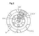
- FIG. 2 shows a further burner plate 10, in which the inner combustion region 2 or torch 3 equal to that FIG. 1 is constructed.
- the outer combustion region 11 or combustion ring 12 now has a basic shape similar to the first combustion region 2, namely centrally without combustion region, with an inner annular combustion region 13 of thickness R5-R3 and at its outer circumference at regular intervals circumferentially integrally then further partial combustion regions 14 in Shape of sectors of height R6-R5 with parallel to each other Pages.
- the sectors 14 may also be considered as ring cutouts.
- the first combustion ring 3 may be circular, the second combustion ring 12 annular.
- the heating power and - characteristic of a dual-circuit or multi-circuit gas burner can be adjusted easily, evenly and sensitively.
- z. B. may be an outer contour of the inner combustion region and / or combustion ring instead of angular sectors in the circumferential direction in waveform, z. B. as a sinusoidal wave, or as a result of hemisphere, etc.
- multi-circuit burners can be used with more than two combustion rings.
- the outer periphery of a burner plate needs not to be circular, for example, oval or rectangular outer contours are possible.
- the maximum outer circumference of a combustion region also need not be circular, for example, oval or rectangular shapes are possible.
- the burner plate is not limited to gas burners, but can also be used for other hobs.
- the inside and outside of the combustion areas may be non-uniform, including angular symmetry, contoured.
Landscapes
- Engineering & Computer Science (AREA)
- Chemical & Material Sciences (AREA)
- Combustion & Propulsion (AREA)
- Mechanical Engineering (AREA)
- General Engineering & Computer Science (AREA)
- Gas Burners (AREA)
- Surface Treatment Of Glass (AREA)
Applications Claiming Priority (1)
| Application Number | Priority Date | Filing Date | Title |
|---|---|---|---|
| DE200710008895 DE102007008895A1 (de) | 2007-02-23 | 2007-02-23 | Brennerplatte |
Publications (2)
| Publication Number | Publication Date |
|---|---|
| EP1962016A2 true EP1962016A2 (fr) | 2008-08-27 |
| EP1962016A3 EP1962016A3 (fr) | 2015-05-27 |
Family
ID=39427712
Family Applications (1)
| Application Number | Title | Priority Date | Filing Date |
|---|---|---|---|
| EP08101726.1A Withdrawn EP1962016A3 (fr) | 2007-02-23 | 2008-02-19 | Plaque de brûleur |
Country Status (2)
| Country | Link |
|---|---|
| EP (1) | EP1962016A3 (fr) |
| DE (1) | DE102007008895A1 (fr) |
Families Citing this family (1)
| Publication number | Priority date | Publication date | Assignee | Title |
|---|---|---|---|---|
| DE202014101097U1 (de) * | 2014-03-11 | 2015-06-12 | Ulrich Dreizler | Brenner mit einer Oberflächenverbrennung |
Citations (1)
| Publication number | Priority date | Publication date | Assignee | Title |
|---|---|---|---|---|
| EP0718551A2 (fr) | 1994-12-20 | 1996-06-26 | Schott Glaswerke | Brûleur radiant avec une plaque de brûleur perméable au gaz |
Family Cites Families (8)
| Publication number | Priority date | Publication date | Assignee | Title |
|---|---|---|---|---|
| US434258A (en) * | 1890-08-12 | Burner for gas or vapor stoves | ||
| US3606612A (en) * | 1969-10-20 | 1971-09-20 | Columbia Gas Syst | Gas burner and control |
| NL176301C (nl) * | 1974-08-24 | Schwank Gmbh | Toestel met ten minste een gasbrander voor een kookplaat. | |
| AT378845B (de) * | 1979-06-06 | 1985-10-10 | Nibelle Pierre Dkfm | Kochfeld fuer einen gasherd |
| DE3728466A1 (de) * | 1987-08-26 | 1989-03-09 | Ego Elektro Blanc & Fischer | Kochgeraet |
| DE4130337C2 (de) * | 1991-09-12 | 2002-05-02 | Ego Elektro Blanc & Fischer | Verfahren zum Betrieb einer elektrischen Heizeinheit und elektrische Heizeinheit |
| JP3624310B2 (ja) * | 2000-07-25 | 2005-03-02 | アタム技研株式会社 | ガス燃焼装置 |
| DE10251548A1 (de) * | 2002-11-05 | 2004-05-19 | Cramer Sr, S.R.O. | Leistungsoptimierter Strahlungsbrenner |
-
2007
- 2007-02-23 DE DE200710008895 patent/DE102007008895A1/de not_active Withdrawn
-
2008
- 2008-02-19 EP EP08101726.1A patent/EP1962016A3/fr not_active Withdrawn
Patent Citations (1)
| Publication number | Priority date | Publication date | Assignee | Title |
|---|---|---|---|---|
| EP0718551A2 (fr) | 1994-12-20 | 1996-06-26 | Schott Glaswerke | Brûleur radiant avec une plaque de brûleur perméable au gaz |
Also Published As
| Publication number | Publication date |
|---|---|
| EP1962016A3 (fr) | 2015-05-27 |
| DE102007008895A1 (de) | 2008-08-28 |
Similar Documents
| Publication | Publication Date | Title |
|---|---|---|
| DE19813691C1 (de) | Kochmulde mit einem Gasbrenner | |
| DE10012578C2 (de) | Kochfeld | |
| EP2290287A2 (fr) | Chapeau de brûleur pour cuisinière à gaz et brûleur doté d'un tel chapeau | |
| DE10315343A1 (de) | Gasbrenner mit Abdeckung | |
| DE3433880A1 (de) | Kochmulde | |
| EP1962016A2 (fr) | Plaque de brûleur | |
| DE19861078C2 (de) | Gaskochgerät | |
| DE102005032980A1 (de) | Brennkammerbaugruppe für einen Verdampferbrenner | |
| WO2014166807A1 (fr) | Support de récipient, système de support de récipient et table de cuisson au gaz | |
| DE102011017683A1 (de) | Topfträger und Gaskochstelle | |
| DE19505470C2 (de) | Topfträger für Gaskochmulden | |
| DE3018794C2 (de) | Gasherd mit einer wärmeübertragenden Platte und einem Strahlungsbrenner | |
| DE69518939T2 (de) | Kochmulde mit positionierbarem Gasbrenner | |
| DE102007021939A1 (de) | Kochfeld | |
| EP2473784B1 (fr) | Dispositif brûleur à gaz et foyer de cuisson à gaz | |
| DE19844551C2 (de) | Gaskochgerät | |
| DE19600322C1 (de) | Einrichtung zur Halterung von gewölbten Kochpfannen | |
| DE102014208409A1 (de) | Heizkörper für ein Gargerät sowie Gargerät mit einem Heizkörper | |
| DE202011003179U1 (de) | Brennofen | |
| DE102018205970A1 (de) | Heizkörper für ein Gargerät und Gargerät | |
| AT396173B (de) | Kochstelle | |
| WO2002016831A1 (fr) | Bruleur a rayonnement gazeux | |
| EP0305962A2 (fr) | Distributeur de chaleur de flammes-gaz pour des ustensiles de cuisine et/ou pour des plaques de cuisson | |
| DE9400835U1 (de) | Adapterelement | |
| AT390138B (de) | Kochplatte fuer gasherde |
Legal Events
| Date | Code | Title | Description |
|---|---|---|---|
| PUAI | Public reference made under article 153(3) epc to a published international application that has entered the european phase |
Free format text: ORIGINAL CODE: 0009012 |
|
| AK | Designated contracting states |
Kind code of ref document: A2 Designated state(s): AT BE BG CH CY CZ DE DK EE ES FI FR GB GR HR HU IE IS IT LI LT LU LV MC MT NL NO PL PT RO SE SI SK TR |
|
| AX | Request for extension of the european patent |
Extension state: AL BA MK RS |
|
| RIN1 | Information on inventor provided before grant (corrected) |
Inventor name: OBERHOMBURG, MARTIN Inventor name: HACOHEN, JOSEPH Inventor name: MASTIO, EMMANUEL Inventor name: CLAUSS, STEPHANE Inventor name: CONRAT, JUAN-IGNACIO |
|
| RAP1 | Party data changed (applicant data changed or rights of an application transferred) |
Owner name: BSH HAUSGERAETE GMBH |
|
| PUAL | Search report despatched |
Free format text: ORIGINAL CODE: 0009013 |
|
| AK | Designated contracting states |
Kind code of ref document: A3 Designated state(s): AT BE BG CH CY CZ DE DK EE ES FI FR GB GR HR HU IE IS IT LI LT LU LV MC MT NL NO PL PT RO SE SI SK TR |
|
| AX | Request for extension of the european patent |
Extension state: AL BA MK RS |
|
| RIC1 | Information provided on ipc code assigned before grant |
Ipc: F24C 3/06 20060101ALI20150420BHEP Ipc: F23D 14/56 20060101ALI20150420BHEP Ipc: F23D 14/08 20060101ALI20150420BHEP Ipc: F23D 14/58 20060101ALI20150420BHEP Ipc: F23D 14/16 20060101AFI20150420BHEP |
|
| 17P | Request for examination filed |
Effective date: 20151127 |
|
| RBV | Designated contracting states (corrected) |
Designated state(s): AT BE BG CH CY CZ DE DK EE ES FI FR GB GR HR HU IE IS IT LI LT LU LV MC MT NL NO PL PT RO SE SI SK TR |
|
| AKX | Designation fees paid |
Designated state(s): AT BE BG CH CY CZ DE DK EE ES FI FR GB GR HR HU IE IS IT LI LT LU LV MC MT NL NO PL PT RO SE SI SK TR |
|
| AXX | Extension fees paid |
Extension state: RS Extension state: BA Extension state: MK Extension state: AL |
|
| STAA | Information on the status of an ep patent application or granted ep patent |
Free format text: STATUS: THE APPLICATION IS DEEMED TO BE WITHDRAWN |
|
| 18D | Application deemed to be withdrawn |
Effective date: 20170901 |