EP1961332B1 - Dispositif d'amortissement pour éléments de meuble mobiles - Google Patents
Dispositif d'amortissement pour éléments de meuble mobiles Download PDFInfo
- Publication number
- EP1961332B1 EP1961332B1 EP08151739A EP08151739A EP1961332B1 EP 1961332 B1 EP1961332 B1 EP 1961332B1 EP 08151739 A EP08151739 A EP 08151739A EP 08151739 A EP08151739 A EP 08151739A EP 1961332 B1 EP1961332 B1 EP 1961332B1
- Authority
- EP
- European Patent Office
- Prior art keywords
- housing
- slide
- spring
- bearing
- energy storage
- Prior art date
- Legal status (The legal status is an assumption and is not a legal conclusion. Google has not performed a legal analysis and makes no representation as to the accuracy of the status listed.)
- Not-in-force
Links
Images


Classifications
-
- E—FIXED CONSTRUCTIONS
- E05—LOCKS; KEYS; WINDOW OR DOOR FITTINGS; SAFES
- E05F—DEVICES FOR MOVING WINGS INTO OPEN OR CLOSED POSITION; CHECKS FOR WINGS; WING FITTINGS NOT OTHERWISE PROVIDED FOR, CONCERNED WITH THE FUNCTIONING OF THE WING
- E05F1/00—Closers or openers for wings, not otherwise provided for in this subclass
- E05F1/08—Closers or openers for wings, not otherwise provided for in this subclass spring-actuated, e.g. for horizontally sliding wings
- E05F1/16—Closers or openers for wings, not otherwise provided for in this subclass spring-actuated, e.g. for horizontally sliding wings for sliding wings
-
- A—HUMAN NECESSITIES
- A47—FURNITURE; DOMESTIC ARTICLES OR APPLIANCES; COFFEE MILLS; SPICE MILLS; SUCTION CLEANERS IN GENERAL
- A47B—TABLES; DESKS; OFFICE FURNITURE; CABINETS; DRAWERS; GENERAL DETAILS OF FURNITURE
- A47B88/00—Drawers for tables, cabinets or like furniture; Guides for drawers
- A47B88/40—Sliding drawers; Slides or guides therefor
- A47B88/453—Actuated drawers
- A47B88/46—Actuated drawers operated by mechanically-stored energy, e.g. by springs
- A47B88/467—Actuated drawers operated by mechanically-stored energy, e.g. by springs self-closing
-
- E—FIXED CONSTRUCTIONS
- E05—LOCKS; KEYS; WINDOW OR DOOR FITTINGS; SAFES
- E05F—DEVICES FOR MOVING WINGS INTO OPEN OR CLOSED POSITION; CHECKS FOR WINGS; WING FITTINGS NOT OTHERWISE PROVIDED FOR, CONCERNED WITH THE FUNCTIONING OF THE WING
- E05F5/00—Braking devices, e.g. checks; Stops; Buffers
- E05F5/003—Braking devices, e.g. checks; Stops; Buffers for sliding wings
-
- A—HUMAN NECESSITIES
- A47—FURNITURE; DOMESTIC ARTICLES OR APPLIANCES; COFFEE MILLS; SPICE MILLS; SUCTION CLEANERS IN GENERAL
- A47B—TABLES; DESKS; OFFICE FURNITURE; CABINETS; DRAWERS; GENERAL DETAILS OF FURNITURE
- A47B2210/00—General construction of drawers, guides and guide devices
- A47B2210/0091—Drawer movement damping
- A47B2210/0094—Drawer damping device with 2 relatively movable parts to convert kinetic energy
-
- E—FIXED CONSTRUCTIONS
- E05—LOCKS; KEYS; WINDOW OR DOOR FITTINGS; SAFES
- E05F—DEVICES FOR MOVING WINGS INTO OPEN OR CLOSED POSITION; CHECKS FOR WINGS; WING FITTINGS NOT OTHERWISE PROVIDED FOR, CONCERNED WITH THE FUNCTIONING OF THE WING
- E05F3/00—Closers or openers with braking devices, e.g. checks; Construction of pneumatic or liquid braking devices
- E05F3/22—Additional arrangements for closers, e.g. for holding the wing in opened or other position
- E05F3/221—Mechanical power-locks, e.g. for holding the wing open or for free-moving zones
-
- E—FIXED CONSTRUCTIONS
- E05—LOCKS; KEYS; WINDOW OR DOOR FITTINGS; SAFES
- E05Y—INDEXING SCHEME RELATING TO HINGES OR OTHER SUSPENSION DEVICES FOR DOORS, WINDOWS OR WINGS AND DEVICES FOR MOVING WINGS INTO OPEN OR CLOSED POSITION, CHECKS FOR WINGS AND WING FITTINGS NOT OTHERWISE PROVIDED FOR, CONCERNED WITH THE FUNCTIONING OF THE WING
- E05Y2201/00—Constructional elements; Accessories therefore
- E05Y2201/40—Motors; Magnets; Springs; Weights; Accessories therefore
- E05Y2201/404—Motors; Magnets; Springs; Weights; Accessories therefore characterised by the function
- E05Y2201/41—Motors; Magnets; Springs; Weights; Accessories therefore characterised by the function for closing
- E05Y2201/412—Motors; Magnets; Springs; Weights; Accessories therefore characterised by the function for closing for the final closing movement
-
- E—FIXED CONSTRUCTIONS
- E05—LOCKS; KEYS; WINDOW OR DOOR FITTINGS; SAFES
- E05Y—INDEXING SCHEME RELATING TO HINGES OR OTHER SUSPENSION DEVICES FOR DOORS, WINDOWS OR WINGS AND DEVICES FOR MOVING WINGS INTO OPEN OR CLOSED POSITION, CHECKS FOR WINGS AND WING FITTINGS NOT OTHERWISE PROVIDED FOR, CONCERNED WITH THE FUNCTIONING OF THE WING
- E05Y2201/00—Constructional elements; Accessories therefore
- E05Y2201/40—Motors; Magnets; Springs; Weights; Accessories therefore
- E05Y2201/47—Springs; Spring tensioners
- E05Y2201/49—Wrap springs
-
- E—FIXED CONSTRUCTIONS
- E05—LOCKS; KEYS; WINDOW OR DOOR FITTINGS; SAFES
- E05Y—INDEXING SCHEME RELATING TO HINGES OR OTHER SUSPENSION DEVICES FOR DOORS, WINDOWS OR WINGS AND DEVICES FOR MOVING WINGS INTO OPEN OR CLOSED POSITION, CHECKS FOR WINGS AND WING FITTINGS NOT OTHERWISE PROVIDED FOR, CONCERNED WITH THE FUNCTIONING OF THE WING
- E05Y2900/00—Application of doors, windows, wings or fittings thereof
- E05Y2900/20—Application of doors, windows, wings or fittings thereof for furnitures, e.g. cabinets
Definitions
- the invention relates to a device for damped Endanyak a movable part, in particular a sliding door, a drawer or other furniture part, with a slidably mounted in a housing and a satchel overlapping slide, which mediates a catch in a Einfangwolf for capturing a movable part Mit Meetings is held and is attenuated by releasing the catch of the force of an energy accumulator of a damping member in an end position.
- a device of the type mentioned above is from DE 20 2005 006 931 U1 previously known.
- the attenuator is formed there as an eddy current brake.
- the energy storage is formed by a helical gear tension spring.
- a similar device with double pneumatic damper describes the DE 20 2004 018 970 U1 .
- the EP 363 642 A1 describes a linear damper with a gear transmission. From the EP 1625 810 A1 is a pneumatic damper for a linear guide known.
- a door closer with a liquid rotary damper describes the WO 2005001227 ,
- the invention has for its object to further develop a generic device nutzsvorteilhaft.
- the energy accumulator has a scroll spring.
- a roll spring has a spring characteristic that rises very slightly.
- a scroll spring or a mainspring consists essentially of a long, wound into a spiral spring steel strip. Such springs are used in self-winding retractors, such as tape measures or roller shutter belts. According to such a rolling or mainspring is used as energy storage. In this case, the roll spring unwinds at the displacement of the slider from the Einfang ein to the end position at most only a few turns.
- the scroll spring is in a power storage housing fixedly connected to the housing.
- the power storage housing is in two parts. It consists of a core part and a shell part. The core part is firmly connected to the housing.
- the shell part has a substantially cup-shaped shape.
- the outer wall of the pot forms a winding zone for a pull rope.
- the spirally wound leaf spring is connected at one end to the core part. She can be there be hooked in a slot.
- the other end of the spring is connected to the rotatably mounted on the core part shell part. Again, the end of the spring form a hook and be hooked into a slot of the jacket wall of the shell part.
- the outer diameter of the shell part is in relation chosen on the displacement path of the slider so that the shell part in the course of the slide displacement a maximum of twice, preferably only once, rotates about its axis.
- the energy storage consisting of a housing core part and a housing shell part and from the scroll spring, can be mounted as an assembly.
- the energy storage can be re-tensioned. This is done by the shell part is rotated relative to the core part by several, preferably one and a half turns in the clamping direction of the spring. This increases the number of spring coils and thus slowly the spring force. The entire device is thus adaptable to different heavy drawers or sliding doors.
- the core part and the shell part may be made of plastic.
- the core member may form a journal which simultaneously holds one end of the spring.
- the bearing pin can protrude through a bottom opening of the cup-shaped shell part. At the opening of the shell part, a bearing collar can be connected, which rests in a bearing groove of the core part.
- the core member may be secured to a portion of the generally two-piece housing with a fastening tab.
- the slide can be made of plastic.
- the bottom or the ceiling of the housing may form a guide rib or a plurality of guide ribs, which engage in a guide groove of the slider.
- the pull cable which is wrapped around the housing shell part and attached to the slider, may be made of nylon.
- a pneumatic damper is provided. This consists of a cylinder, which rests in a fork-shaped receptacle of the slider. This receptacle is formed by two spaced apart retaining walls.
- the belonging to the pneumatic damper piston rod is connected on one side via a fixing pin to the housing.
- the other end of the piston rod carries a piston, which is slidably guided in the cylinder.
- the piston has an air passage opening, so that a damping of the slider movement is generated. It is essential that the slider movement dampened in the tightening direction is.
- the piston can be designed so that when the slide is displaced in the opposite direction, ie in the opening direction, considerably more air can flow over the piston, so that there is no or only little damping in this direction of movement.
- the sear is pivotally mounted on a boom of the slider. It has a guide pin, which is guided in two congruent guide slots of the housing.
- the squeegee also has a locking pin, which is also guided in the guide slot.
- the guide slot has at its one end an angled portion which is provided with a latching niche. In this detent recess of the locking pin occurs when the device is in its catch position.
- the pin is positively controlled in this latching niche, when the sling pawl, from a drawer or a sliding door, is dragged from the end position to the catching position. Along with this shift, the energy storage is stored.
- the sling pawl turns transversely in this catching position, so that a catching jaw formed by the squeezing catch can catch a catch, which is firmly connected to the door or the drawer.
- the cylinder forming the damping member is connected in the same material as the slider, which is longitudinally guided within the housing.
- the cylinder does not need to have a lid. But he has a material integrally molded cylinder bottom. The piston is anchored with its piston rod on the housing tensile strength and protrudes with his head in the cylinder.
- the piston has an air passage opening, which is designed as a valve. From the slider can protrude a boom which rotatably supports a guide pin of the sear in a bearing eye. A guide pin of the adjacent detent pin of the sear is guided in a guide slot which has an acute-angled locking projection at the end.
- the catch has a stop arm against the a driver attached to the rear of the sliding door strikes when it enters the safety jaw. In a proper operation, this is done with inclined sear, so that the driver overflows due to the inclination receding lying pressure arm of the sear.
- the pressure arm forming the pressure flank emerges from the path of movement of the driver as a result of a pivoting of the safety catch.
- the pressure flank is part of a catch.
- the catch is a hinged by a spring hinge on the sear arm.
- the spring hinge forms a spring. This is preloaded.
- a tie rod attacks on the catch.
- the catch can shift against the tie rod. He has a ramp, on which the driver can accumulate.
- the satchel is a unitary injection molded part.
- the tie rod is materially connected to the sear and forms a hammer head, which rests in a holding chamber of the latch.
- the pneumatic cylinder is the same material with the slider and material unit connected to a boom. At the end of the boom is a bearing eye, in which a guide pin of the sear is guided. A distance from the guide pin locking pin is also guided in a guide slot of the housing. The guide slot forms an acute-angled locking portion, in which the locking pin can occur.
- an arcuate detent spring is attached the same material.
- first latching recess in which the latching pin rests when it is in the guide slot.
- the detent spring forms a second detent recess, in which the guide pin is located when it is in the detent portion of the guide slot.
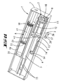
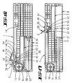
- the device shown in the drawings can be secured in the region of an upper running rail 40 of a sliding door on the ceiling 42 of a carcass.
- the housing 1 is fastened to the rear of the running rail 40.
- the running rail 40 has two guide grooves 41 for the rollers of the two sliding doors, not shown.
- a driver 6 is attached to the back of the sliding door. This driver cooperates with a sear 2 of the device.
- the sear 2 has a catch mouth 37. This catch mouth is formed by a stop arm 38 and a pressure arm 39. In the in Fig. 3 shown fishing position is the catch mouth 37 in an oblique opening position. If the sliding door is closed, the catch 6 comes against the stop arm 38 of the catch mouth 37. The catch 2 is pivoted. A locking pin 5 of the sear 2 thereby leaves a detent niche 4 of a section 14 'of a guide slot 14.
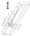
- the housing is in two parts. It has a first housing part 1 'and a second housing part 1 ", the latter forming the screw-on console with which the housing 1 is fastened to the cover 42 of the carcass
- Both housing parts 1', 1" form a guide formed by two ribs 15 for one Slider 3.
- the slider 3 has two ribs projecting in the direction of the housing part 1 ", which form between them a guide groove 16 in which the guide ribs 15 are in.
- the slider 3 has a boom on which the sear pawl 2 is pivotably mounted
- the guide pin 13 projects beyond two guide slots 14, 14 'which lie congruently to each other, wherein each of the two housing parts 1', 1 "is associated with a guide slot 14, 14 '.
- the locking pin 5 projects into the two guide slots 14, 14 '.
- the catch 2 is located outside the housing 1.
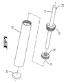
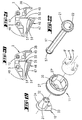
- the energy storage 7 is formed by a mounting unit.
- This mounting unit consists of a core part 10, which can be fastened with a fastening tab 33 on the housing. From the fastening tab 33 projects from a bearing pin 31.
- the bearing pin 31 is surrounded by a bearing collar 34 at a slight distance. Between bearing collar 34 and bearing pin 31, an annular bearing groove is formed.
- the bearing pin 31 extends through a bottom opening 30, which forms a bearing opening, the bottom 29 of a cup-shaped housing shell part 11.
- the pot wall is formed by an open annular wall 27. On the outer wall, the annular wall 27 has a partial circumferential ridge 28. An extension of the bottom 29 also forms a peripheral ridge 29 '.
- a scroll spring 9 This consists of a multi-wound leaf spring.
- One end 9 "of the leaf spring 9 is fastened in a fastening slot 32 of the bearing pin 31 projecting into the pot cavity
- the other end 9 'of the leaf spring 9 is fastened in a fastening slot 26 of the annular wall 27.
- the circumferential length of the outer wall of the annular wall 27 corresponds approximately to that of FIG Length of the guide slot 14.
- a pull rope 12 is attached, for example, nylon or other suitable material.
- the other end of the pull cable 12 is connected to the housing shell part 11, wherein the pull rope with several turns on the winding surface of the shell part 11 between the ribs 28, 29 'rests.
- the housing part 1 "forms a bearing cup 36, in which the housing shell part 11 is rotatably mounted.” This bearing cup supports the housing shell part 11 on the side opposite the bearing collar 35.
- the other housing part 1 ' forms a mounting pin 44 opposite the bearing cup 36, which in FIG engages a cavity of the bearing pin 31.
- a further pin 45 is provided for the rotationally fixed attachment of the fastening tab 33 on the housing part 1 '.
- the slide 3 has on its side opposite the boom 43 two spaced apart retaining walls 24, 25. Between the two retaining walls 24, 25, the cylinder 19 extends a pneumatic damper 8.
- a piston 21 In the cylinder 19, which is closed with a plug 20, is located a piston 21.
- the piston 21 is screwed onto one end of a piston rod 17.
- a cap 18 In the plug 20 opposite the opening of the cylinder 19, a cap 18 is screwed.
- This has a central opening which supports the piston rod 17.
- the piston 21 opposite the end of the piston rod 17 is fixedly connected to a fastening pin 23 with the housing 1.
- the piston 21 performs a relative movement relative to the cylinder 19. In this case, air flows through the piston.
- the piston has an air passage opening 22.
- the width of the air passage opening 22 determines the degree of damping. There are measures provided that increases the effective air passage opening when the slide 3 of his in the Fig. 2 illustrated end position in the in Fig. 3 shifted catch position, which is associated with the opening of the sliding door. This movement should be done undamped. A damping should be done in the opposite direction, when the energy storage discharges.
- the housing shell part 11 Since the circumference of the housing shell part 11 has a length which substantially corresponds to the length of the guide slot 14, the housing shell part 11 is rotated substantially once during the displacement of the slider 3 from the end position to the catching position.
- the preloaded roll spring 9 is only slightly further tensioned during this shift. The spring tension increases only slightly.
- the scroll spring 9 By repeatedly rotating the shell part 11 relative to the core part 10, however, the scroll spring 9 can be significantly stretched or relaxed. By these measures, the spring force of the scroll spring can be adapted to different requirements. During normal use, ie when tensioning the scroll spring in the course of opening the sliding door or when relaxing the scroll spring when closing the sliding door whose spring force changes only slightly.
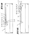
- a housing half 1 has a guide slot 14 arranged near the edge of the housing, in which a guide pin 13 and a latching pin 5 of a sear 2 are guided.
- the sear 2 is located outside the housing.
- the guide slot 14 has at its end an acute-angled extension 14 ', in which the locking pin 5 can dip. This has a pivoting of the sear 2 from a driving position into a catching position result. In this position, the driver 6 a sliding door in the space between the pressure arm 39 and stop arm 38 occur.
- the pressure arm 39 is an acute-angled extension of a catch 46.
- the catch is formed by a plastic arm, which is fastened with a film hinge 48 on the catching pawl body.
- the film hinge 48 forms a leaf spring.
- the pressure arm 39 has a chamber 51 with a cross-section reduced chamber opening 51 '. Opposite the chamber opening 51 'is rooting on the catching pawl body 2, a tie rod 49.
- the tie rod 49 has a hammerhead head 50. In the in Fig. 21 shown manufacturing position leaves the catching pawl part 2, the injection molding machine it manufactures. In this state, the hammer head 50 is disposed outside the chamber 51.
- the leaf spring forming a film hinge 48 is relaxed. The flycatcher will then be in the in Fig. 20 brought bias position shown by the hammer head 50 is pivoted into the chamber 51.
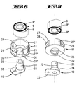
- An inner end 9 "of the roller spring 9 inserts into a fastening slot 32 of a housing core part 10.
- An outer end 9 ' is fastened to a holding body 27' of a ring wall body 27, on the cylindrical outer surface of which a pull cable is wound.
- the Switzerlandsseil attacks a slider 3.
- This slide is guided on the housing ribs and forms the same material from the boom 43, which forms a bearing eye 52 at its free end, in which the guide pin 13 of the sear 2 is rotatably mounted.
- the slider 3 On the side facing away from the boom 43, the slider 3 is integrally formed with a pneumatic cylinder 19, which is part of a pneumatic damper 8.
- the pneumatic cylinder 19 has an opening in which the head 21 of a piston is inserted.
- the piston rod 17 has at its end a holding plate 57, which rests in a groove 56 of the wall of the housing 1. Again, the head of the piston 21 has an overflow.
- W-shaped leaf spring 53 in addition to a slide 3 material integrally formed, W-shaped leaf spring 53.
Claims (12)
- Dispositif pour le serrage final amorti d'une pièce mobile, en particulier d'une porte coulissante, d'un tiroir coulissant ou d'une autre pièce de mobilier, avec un coulisseau (3) agencé de manière coulissante dans un boîtier (1) et hébergeant un cliquet de capture (2), qui est maintenu au moyen d'un cran (4, 5) dans une position de capture en vue de la capture d'un toc d'entraînement (6) affecté à la pièce mobile et qui, après soulèvement du cran (4, 5) par la force d'un accumulateur d'énergie (7), de manière amortie par un élément d'amortissement (8), peut être déplacé dans une position finale, caractérisé en ce que l'accumulateur d'énergie (7) présente un ressort spinale (9), qui est hébergé par un boîtier d'accumulateur d'énergie présentant une pièce centrale (10) reliée de manière fixe avec le boîtier (1) et une pièce d'enveloppe (11) montée de manière à pouvoir être mise en rotation par la pièce centrale, le coulisseau (3) étant relié à l'accumulateur d'énergie (7) par un câble de traction (12) enroulé sur la pièce d'enveloppe (11).
- Dispositif selon la revendication 1, caractérisé en ce que la pièce centrale (10) est fixée au niveau du boîtier (1) par une patte de fixation (33).
- Dispositif selon l'une quelconque des revendications précédentes, caractérisé en ce que la pièce d'enveloppe (11) présente une configuration en forme de pot, avec une collerette de montage (35), se raccordant à une ouverture de montage (30) du fond de pot (29), qui repose dans une rainure de montage formée par une collerette de montage (34) de la pièce centrale (10).
- Dispositif selon l'une quelconque des revendications précédentes, caractérisé en ce que le ressort spinale (9) est maintenu dans une fente de fixation (32) d'un tourillon (31) de la pièce centrale (10) par une première extrémité formant crochet (9"), et dans une fente de fixation (26) d'une paroi annulaire (27, 27') de la pièce d'enveloppe (11) par une seconde extrémité (9').
- Dispositif selon l'une quelconque des revendications précédentes, caractérisé par des étais périphériques (28, 29') agencés sur le pourtour de la pièce d'enveloppe (11).
- Dispositif selon l'une quelconque des revendications précédentes, caractérisé en ce que le coulisseau (3) est monté coulissant au moyen d'une rainure de guidage (16) sur une ou plusieurs nervures de guidage (15) d'une pièce de boîtier (1', 1").
- Dispositif selon l'une quelconque des revendications précédentes, caractérisé en ce qu'un amortisseur pneumatique (8) formant l'atténuateur présente un cylindre (19) dans lequel est agencé un piston (21) fixé au niveau de l'extrémité d'une tige de piston (17).
- Dispositif selon la revendication 7, caractérisé en ce que le cylindre (19) se situe entre deux parois de maintien (24, 25) du coulisseau (3) et la tige de piston (17) est fixée au niveau du boîtier (1).
- Dispositif selon l'une quelconque des revendications précédentes, caractérisé en ce que le cliquet de capture (2) présente un flan de pression (39) qui est formé par un loqueteau.
- Dispositif selon la revendication 9, caractérisé en ce que le loqueteau (46) présente un ressort formé par une charnière pelliculaire (48) et maintenu en précontrainte au moyen d'un tirant (49).
- Dispositif selon l'une quelconque des revendications 7 à 10, caractérisé en ce que le cylindre (19) et le coulisseau (3) forment un ensemble présentant une homogénéité de matériau.
- Dispositif selon l'une quelconque des revendications précédentes, caractérisé par un ressort à cran (53) formé sur le coulisseau, pour fixer un tourillon à cran (5) du cliquet de capture (2) dans respectivement une des deux positions d'encliquetage (54, 55).
Applications Claiming Priority (1)
| Application Number | Priority Date | Filing Date | Title |
|---|---|---|---|
| DE102007009076A DE102007009076A1 (de) | 2007-02-23 | 2007-02-23 | Dämpfungseinrichtung für bewegbare Möbelteile |
Publications (2)
| Publication Number | Publication Date |
|---|---|
| EP1961332A1 EP1961332A1 (fr) | 2008-08-27 |
| EP1961332B1 true EP1961332B1 (fr) | 2011-04-20 |
Family
ID=39420518
Family Applications (1)
| Application Number | Title | Priority Date | Filing Date |
|---|---|---|---|
| EP08151739A Not-in-force EP1961332B1 (fr) | 2007-02-23 | 2008-02-21 | Dispositif d'amortissement pour éléments de meuble mobiles |
Country Status (3)
| Country | Link |
|---|---|
| EP (1) | EP1961332B1 (fr) |
| AT (1) | ATE505976T1 (fr) |
| DE (2) | DE102007009076A1 (fr) |
Families Citing this family (17)
| Publication number | Priority date | Publication date | Assignee | Title |
|---|---|---|---|---|
| MX2007005260A (es) * | 2004-11-05 | 2007-07-09 | Accuride Int Inc | Mecanismo de movimiento amortiguado y corredera que se incorpora al mismo. |
| DE202008000932U1 (de) * | 2008-01-22 | 2009-05-28 | Hettich-Heinze Gmbh & Co. Kg | Dämpfungseinrichtung für bewegbare Möbelteile |
| DE102008051360A1 (de) * | 2008-10-15 | 2010-05-12 | Karl Simon Gmbh & Co. Kg | Einzugsvorrichtung |
| CN101810404B (zh) * | 2009-02-20 | 2011-10-19 | 李绍汉 | 抽屉缓冲器 |
| DE202009002715U1 (de) | 2009-02-25 | 2010-07-15 | Paul Hettich Gmbh & Co. Kg | Auszugsführung für ein Möbelauszugsteil |
| DE202009011042U1 (de) | 2009-08-13 | 2010-12-30 | Weber & Co. Gmbh Kg | Schiebetürbeschlag |
| DE202009014882U1 (de) * | 2009-12-18 | 2011-05-05 | Hettich-Heinze Gmbh & Co. Kg | Beschlaggarnitur für zwei Schiebetürflügel |
| DE102010000341A1 (de) * | 2010-02-08 | 2011-08-11 | Karl Simon GmbH & Co. KG, 78733 | Einzugvorrichtung für Möbel |
| DE102010000340C5 (de) * | 2010-02-08 | 2019-12-05 | Karl Simon Gmbh & Co. Kg | Einzugvorrichtung und -anordnung für Schiebetüren sowie ein Verfahren zur Bedienung einer Schiebetür |
| DE202010008860U1 (de) * | 2010-10-21 | 2012-01-23 | Hücking GmbH | Beschlagsystem für Schiebetüren |
| DE102010061160B4 (de) * | 2010-12-10 | 2023-10-26 | Hettich-Heinze Gmbh & Co. Kg | Schließ- und Dämpfungsvorrichtung für bewegbare Möbelteile |
| DE102011115662B4 (de) * | 2011-09-28 | 2013-04-25 | Door & Window Hardware Co. | Verstellbare automatische Rückstellvorrichtung mit Pufferwirkung für eine Schiebetür |
| DE102015203812B4 (de) * | 2015-03-03 | 2020-11-12 | Hahn-Gasfedern Gmbh | Feder- und/oder Dämpferelement |
| WO2017192112A1 (fr) * | 2016-06-30 | 2017-11-09 | Rollmech Automotive Sanayi Ve Ticaret Anonim Sirketi | Butoir de porte coulissante |
| JP6962567B2 (ja) * | 2018-04-26 | 2021-11-05 | 日本アキュライド株式会社 | 自動引き込み装置付きスライドレール |
| CN112353152B (zh) * | 2020-11-16 | 2022-08-05 | 湖州品创孵化器有限公司 | 一种金属家具插栓孔体结构 |
| AT526130A1 (de) * | 2022-04-29 | 2023-11-15 | Blum Gmbh Julius | Anordnung zur Führung wenigstens eines bewegbaren Möbelteiles relativ zu einem Möbelkorpus |
Family Cites Families (13)
| Publication number | Priority date | Publication date | Assignee | Title |
|---|---|---|---|---|
| US4004372A (en) * | 1975-04-14 | 1977-01-25 | Doormaid, Inc. | Sliding door closer and method and apparatus for installing the same |
| JPH0270879A (ja) | 1988-09-06 | 1990-03-09 | Sankyo Seiki Mfg Co Ltd | ドアクローザー |
| BR0303572A (pt) * | 2002-03-21 | 2004-04-20 | Blum Gmbh Julius | Dispositivo pneumático de freagem e de amortecimento, especialmente para partes de móveis que podem ser movidas |
| DE20218927U1 (de) * | 2002-12-05 | 2003-02-13 | Hettich Heinze Gmbh & Co Kg | Dämpfungs- und Einzugsvorrichtung für Schiebetüren |
| WO2005044046A1 (fr) | 2003-01-10 | 2005-05-19 | Alfit Ag | Mecanisme de retrait automatique destine a des guides de tiroirs |
| CA2521444C (fr) | 2003-05-13 | 2008-07-08 | Grass America Inc. | Mecanisme de fermeture d'un tiroir |
| JP3930459B2 (ja) | 2003-06-30 | 2007-06-13 | 株式会社シモダイラ | 引戸の戸閉装置 |
| DE20315124U1 (de) | 2003-09-29 | 2004-02-26 | Hettich-Heinze Gmbh & Co. Kg | Selbsteinzug mit Dämpfer für bewegliche Möbelteile |
| DE102004038708A1 (de) | 2004-08-10 | 2006-03-09 | Schock Metallwerk Gmbh | Bewegungsdämpfungsvorrichtung |
| DE202004018970U1 (de) | 2004-12-08 | 2005-02-03 | Hettich-Heinze Gmbh & Co. Kg | Auszug, insbesondere Schwerlastauszug mit mindestens einem Schiebelement |
| DE102005010226A1 (de) * | 2005-03-05 | 2006-03-30 | Daimlerchrysler Ag | Verschiebevorrichtung mit temperaturabhängiger Antriebskraft |
| DE202005006931U1 (de) | 2005-04-28 | 2006-08-31 | Hettich-Heinze Gmbh & Co. Kg | Dämpfungseinrichtung für bewegbare Möbelteile |
| DE102005038727A1 (de) * | 2005-08-15 | 2007-02-22 | Miele & Cie. Kg | Waschmaschine mit Waschmittel- und Spülmittelschublade mit die Schliess- oder Öffnungsbewegung unterstützenden Mitteln |
-
2007
- 2007-02-23 DE DE102007009076A patent/DE102007009076A1/de not_active Ceased
-
2008
- 2008-02-21 DE DE502008003237T patent/DE502008003237D1/de active Active
- 2008-02-21 EP EP08151739A patent/EP1961332B1/fr not_active Not-in-force
- 2008-02-21 AT AT08151739T patent/ATE505976T1/de active
Also Published As
| Publication number | Publication date |
|---|---|
| DE502008003237D1 (de) | 2011-06-01 |
| ATE505976T1 (de) | 2011-05-15 |
| EP1961332A1 (fr) | 2008-08-27 |
| DE102007009076A1 (de) | 2008-08-28 |
Similar Documents
| Publication | Publication Date | Title |
|---|---|---|
| EP1961332B1 (fr) | Dispositif d'amortissement pour éléments de meuble mobiles | |
| EP2948023B1 (fr) | Dispositif d'accélération pour parties mobiles de meubles ou d'appareils ménagers | |
| AT509923B1 (de) | Einzugsvorrichtung zum einziehen eines bewegbar gelagerten möbelteiles | |
| DE10253138B4 (de) | Türvorrichtung für ein Fahrzeug und Verfahren zum Steuern einer Bewegung einer Tür | |
| DE102010051518B4 (de) | Türverschluss für ein elektrisches Haushaltsgerät | |
| EP0985847A2 (fr) | Dispositif de limitation de force | |
| EP2217782A1 (fr) | Dispositif de traction et d'amortissement d'une porte coulissante logée dans un rail profilé pour le guidage de mécanismes de roulement, vers la position terminale | |
| EP2088229B1 (fr) | Machine à coudre et dispositif de bobinage pour une telle machine à coudre | |
| WO2016037919A1 (fr) | Dispositif pour enrouler und'enroulement de câble | |
| EP2335476B1 (fr) | Dispositif de freinage pour un rouleau de corde d'une laisse enroulable et déroulable mécaniquement pour mener des animaux | |
| DE202009005255U1 (de) | Rastsystem | |
| EP3013187A1 (fr) | Dispositif de rentrée, guide de retrait avec dispositif de rentrée et meuble équipé d'un guide de retrait | |
| DE4015404A1 (de) | Rohrschelle | |
| DE20318929U1 (de) | Einzugsautomatik für Schubladen-Ausziehführungen | |
| DE202005016007U1 (de) | Spule für eine Angelrolle | |
| DE102010038247A1 (de) | Schließsystem eines ausziehbaren Möbelteils und Möbel | |
| DE102014218019B3 (de) | Vorrichtung zum Aufwickeln eines Kabels | |
| DE102009012921A1 (de) | Gerät oder Möbel mit einer Schublade | |
| EP2138621B1 (fr) | Machine à coudre et dispositif de bobinage pour une telle machine à coudre | |
| DE102006056791A1 (de) | Federgelenk | |
| DE3722604C2 (de) | Wendevorrichtung für Rafflamellenstores | |
| WO2019042836A1 (fr) | Dispositif d'insertion permettant d'insérer une partie mobile d'un meuble ou d'un appareil ménager dans une position finale | |
| CH713355A2 (de) | Lagerteil für eine Stoffwalze einer Wetterschutzvorrichtung. | |
| EP3955773B1 (fr) | Dispositif rétractable pour une partie mobile | |
| DE102016121609A1 (de) | Gurtaufroller |
Legal Events
| Date | Code | Title | Description |
|---|---|---|---|
| PUAI | Public reference made under article 153(3) epc to a published international application that has entered the european phase |
Free format text: ORIGINAL CODE: 0009012 |
|
| AK | Designated contracting states |
Kind code of ref document: A1 Designated state(s): AT BE BG CH CY CZ DE DK EE ES FI FR GB GR HR HU IE IS IT LI LT LU LV MC MT NL NO PL PT RO SE SI SK TR |
|
| AX | Request for extension of the european patent |
Extension state: AL BA MK RS |
|
| 17P | Request for examination filed |
Effective date: 20090226 |
|
| 17Q | First examination report despatched |
Effective date: 20090331 |
|
| AKX | Designation fees paid |
Designated state(s): AT BE BG CH CY CZ DE DK EE ES FI FR GB GR HR HU IE IS IT LI LT LU LV MC MT NL NO PL PT RO SE SI SK TR |
|
| GRAP | Despatch of communication of intention to grant a patent |
Free format text: ORIGINAL CODE: EPIDOSNIGR1 |
|
| GRAS | Grant fee paid |
Free format text: ORIGINAL CODE: EPIDOSNIGR3 |
|
| GRAA | (expected) grant |
Free format text: ORIGINAL CODE: 0009210 |
|
| AK | Designated contracting states |
Kind code of ref document: B1 Designated state(s): AT BE BG CH CY CZ DE DK EE ES FI FR GB GR HR HU IE IS IT LI LT LU LV MC MT NL NO PL PT RO SE SI SK TR |
|
| REG | Reference to a national code |
Ref country code: GB Ref legal event code: FG4D Free format text: NOT ENGLISH |
|
| REG | Reference to a national code |
Ref country code: CH Ref legal event code: EP |
|
| REG | Reference to a national code |
Ref country code: IE Ref legal event code: FG4D Free format text: LANGUAGE OF EP DOCUMENT: GERMAN |
|
| REF | Corresponds to: |
Ref document number: 502008003237 Country of ref document: DE Date of ref document: 20110601 Kind code of ref document: P |
|
| REG | Reference to a national code |
Ref country code: DE Ref legal event code: R096 Ref document number: 502008003237 Country of ref document: DE Effective date: 20110601 |
|
| REG | Reference to a national code |
Ref country code: NL Ref legal event code: VDEP Effective date: 20110420 |
|
| LTIE | Lt: invalidation of european patent or patent extension |
Effective date: 20110420 |
|
| PG25 | Lapsed in a contracting state [announced via postgrant information from national office to epo] |
Ref country code: PT Free format text: LAPSE BECAUSE OF FAILURE TO SUBMIT A TRANSLATION OF THE DESCRIPTION OR TO PAY THE FEE WITHIN THE PRESCRIBED TIME-LIMIT Effective date: 20110822 Ref country code: SE Free format text: LAPSE BECAUSE OF FAILURE TO SUBMIT A TRANSLATION OF THE DESCRIPTION OR TO PAY THE FEE WITHIN THE PRESCRIBED TIME-LIMIT Effective date: 20110420 Ref country code: NO Free format text: LAPSE BECAUSE OF FAILURE TO SUBMIT A TRANSLATION OF THE DESCRIPTION OR TO PAY THE FEE WITHIN THE PRESCRIBED TIME-LIMIT Effective date: 20110720 Ref country code: LT Free format text: LAPSE BECAUSE OF FAILURE TO SUBMIT A TRANSLATION OF THE DESCRIPTION OR TO PAY THE FEE WITHIN THE PRESCRIBED TIME-LIMIT Effective date: 20110420 Ref country code: HR Free format text: LAPSE BECAUSE OF FAILURE TO SUBMIT A TRANSLATION OF THE DESCRIPTION OR TO PAY THE FEE WITHIN THE PRESCRIBED TIME-LIMIT Effective date: 20110420 |
|
| REG | Reference to a national code |
Ref country code: IE Ref legal event code: FD4D |
|
| PG25 | Lapsed in a contracting state [announced via postgrant information from national office to epo] |
Ref country code: CY Free format text: LAPSE BECAUSE OF FAILURE TO SUBMIT A TRANSLATION OF THE DESCRIPTION OR TO PAY THE FEE WITHIN THE PRESCRIBED TIME-LIMIT Effective date: 20110420 Ref country code: ES Free format text: LAPSE BECAUSE OF FAILURE TO SUBMIT A TRANSLATION OF THE DESCRIPTION OR TO PAY THE FEE WITHIN THE PRESCRIBED TIME-LIMIT Effective date: 20110731 Ref country code: FI Free format text: LAPSE BECAUSE OF FAILURE TO SUBMIT A TRANSLATION OF THE DESCRIPTION OR TO PAY THE FEE WITHIN THE PRESCRIBED TIME-LIMIT Effective date: 20110420 Ref country code: IS Free format text: LAPSE BECAUSE OF FAILURE TO SUBMIT A TRANSLATION OF THE DESCRIPTION OR TO PAY THE FEE WITHIN THE PRESCRIBED TIME-LIMIT Effective date: 20110820 Ref country code: SI Free format text: LAPSE BECAUSE OF FAILURE TO SUBMIT A TRANSLATION OF THE DESCRIPTION OR TO PAY THE FEE WITHIN THE PRESCRIBED TIME-LIMIT Effective date: 20110420 Ref country code: LV Free format text: LAPSE BECAUSE OF FAILURE TO SUBMIT A TRANSLATION OF THE DESCRIPTION OR TO PAY THE FEE WITHIN THE PRESCRIBED TIME-LIMIT Effective date: 20110420 |
|
| PG25 | Lapsed in a contracting state [announced via postgrant information from national office to epo] |
Ref country code: NL Free format text: LAPSE BECAUSE OF FAILURE TO SUBMIT A TRANSLATION OF THE DESCRIPTION OR TO PAY THE FEE WITHIN THE PRESCRIBED TIME-LIMIT Effective date: 20110420 |
|
| PG25 | Lapsed in a contracting state [announced via postgrant information from national office to epo] |
Ref country code: EE Free format text: LAPSE BECAUSE OF FAILURE TO SUBMIT A TRANSLATION OF THE DESCRIPTION OR TO PAY THE FEE WITHIN THE PRESCRIBED TIME-LIMIT Effective date: 20110420 Ref country code: CZ Free format text: LAPSE BECAUSE OF FAILURE TO SUBMIT A TRANSLATION OF THE DESCRIPTION OR TO PAY THE FEE WITHIN THE PRESCRIBED TIME-LIMIT Effective date: 20110420 Ref country code: IE Free format text: LAPSE BECAUSE OF FAILURE TO SUBMIT A TRANSLATION OF THE DESCRIPTION OR TO PAY THE FEE WITHIN THE PRESCRIBED TIME-LIMIT Effective date: 20110420 |
|
| PLBE | No opposition filed within time limit |
Free format text: ORIGINAL CODE: 0009261 |
|
| STAA | Information on the status of an ep patent application or granted ep patent |
Free format text: STATUS: NO OPPOSITION FILED WITHIN TIME LIMIT |
|
| PG25 | Lapsed in a contracting state [announced via postgrant information from national office to epo] |
Ref country code: SK Free format text: LAPSE BECAUSE OF FAILURE TO SUBMIT A TRANSLATION OF THE DESCRIPTION OR TO PAY THE FEE WITHIN THE PRESCRIBED TIME-LIMIT Effective date: 20110420 Ref country code: DK Free format text: LAPSE BECAUSE OF FAILURE TO SUBMIT A TRANSLATION OF THE DESCRIPTION OR TO PAY THE FEE WITHIN THE PRESCRIBED TIME-LIMIT Effective date: 20110420 Ref country code: PL Free format text: LAPSE BECAUSE OF FAILURE TO SUBMIT A TRANSLATION OF THE DESCRIPTION OR TO PAY THE FEE WITHIN THE PRESCRIBED TIME-LIMIT Effective date: 20110420 Ref country code: RO Free format text: LAPSE BECAUSE OF FAILURE TO SUBMIT A TRANSLATION OF THE DESCRIPTION OR TO PAY THE FEE WITHIN THE PRESCRIBED TIME-LIMIT Effective date: 20110420 |
|
| 26N | No opposition filed |
Effective date: 20120123 |
|
| REG | Reference to a national code |
Ref country code: DE Ref legal event code: R097 Ref document number: 502008003237 Country of ref document: DE Effective date: 20120123 |
|
| PG25 | Lapsed in a contracting state [announced via postgrant information from national office to epo] |
Ref country code: IT Free format text: LAPSE BECAUSE OF FAILURE TO SUBMIT A TRANSLATION OF THE DESCRIPTION OR TO PAY THE FEE WITHIN THE PRESCRIBED TIME-LIMIT Effective date: 20110420 |
|
| BERE | Be: lapsed |
Owner name: WEBER & CO. G.M.B.H. KG Effective date: 20120228 |
|
| PG25 | Lapsed in a contracting state [announced via postgrant information from national office to epo] |
Ref country code: MC Free format text: LAPSE BECAUSE OF NON-PAYMENT OF DUE FEES Effective date: 20120229 |
|
| REG | Reference to a national code |
Ref country code: CH Ref legal event code: PL |
|
| GBPC | Gb: european patent ceased through non-payment of renewal fee |
Effective date: 20120221 |
|
| PG25 | Lapsed in a contracting state [announced via postgrant information from national office to epo] |
Ref country code: LI Free format text: LAPSE BECAUSE OF NON-PAYMENT OF DUE FEES Effective date: 20120229 Ref country code: CH Free format text: LAPSE BECAUSE OF NON-PAYMENT OF DUE FEES Effective date: 20120229 |
|
| REG | Reference to a national code |
Ref country code: FR Ref legal event code: ST Effective date: 20121031 |
|
| PG25 | Lapsed in a contracting state [announced via postgrant information from national office to epo] |
Ref country code: BE Free format text: LAPSE BECAUSE OF NON-PAYMENT OF DUE FEES Effective date: 20120228 |
|
| PG25 | Lapsed in a contracting state [announced via postgrant information from national office to epo] |
Ref country code: GB Free format text: LAPSE BECAUSE OF NON-PAYMENT OF DUE FEES Effective date: 20120221 Ref country code: FR Free format text: LAPSE BECAUSE OF NON-PAYMENT OF DUE FEES Effective date: 20120229 |
|
| PG25 | Lapsed in a contracting state [announced via postgrant information from national office to epo] |
Ref country code: BG Free format text: LAPSE BECAUSE OF FAILURE TO SUBMIT A TRANSLATION OF THE DESCRIPTION OR TO PAY THE FEE WITHIN THE PRESCRIBED TIME-LIMIT Effective date: 20110720 |
|
| PG25 | Lapsed in a contracting state [announced via postgrant information from national office to epo] |
Ref country code: MT Free format text: LAPSE BECAUSE OF FAILURE TO SUBMIT A TRANSLATION OF THE DESCRIPTION OR TO PAY THE FEE WITHIN THE PRESCRIBED TIME-LIMIT Effective date: 20110420 |
|
| REG | Reference to a national code |
Ref country code: DE Ref legal event code: R082 Ref document number: 502008003237 Country of ref document: DE Representative=s name: KOHLER SCHMID MOEBUS PATENTANWAELTE, DE Ref country code: DE Ref legal event code: R082 Ref document number: 502008003237 Country of ref document: DE Representative=s name: KOHLER SCHMID MOEBUS PATENTANWAELTE PARTNERSCH, DE |
|
| REG | Reference to a national code |
Ref country code: AT Ref legal event code: MM01 Ref document number: 505976 Country of ref document: AT Kind code of ref document: T Effective date: 20130221 |
|
| PG25 | Lapsed in a contracting state [announced via postgrant information from national office to epo] |
Ref country code: TR Free format text: LAPSE BECAUSE OF FAILURE TO SUBMIT A TRANSLATION OF THE DESCRIPTION OR TO PAY THE FEE WITHIN THE PRESCRIBED TIME-LIMIT Effective date: 20110420 |
|
| PG25 | Lapsed in a contracting state [announced via postgrant information from national office to epo] |
Ref country code: LU Free format text: LAPSE BECAUSE OF NON-PAYMENT OF DUE FEES Effective date: 20120221 Ref country code: AT Free format text: LAPSE BECAUSE OF NON-PAYMENT OF DUE FEES Effective date: 20130221 |
|
| PG25 | Lapsed in a contracting state [announced via postgrant information from national office to epo] |
Ref country code: HU Free format text: LAPSE BECAUSE OF FAILURE TO SUBMIT A TRANSLATION OF THE DESCRIPTION OR TO PAY THE FEE WITHIN THE PRESCRIBED TIME-LIMIT Effective date: 20080221 |
|
| PG25 | Lapsed in a contracting state [announced via postgrant information from national office to epo] |
Ref country code: GR Free format text: LAPSE BECAUSE OF FAILURE TO SUBMIT A TRANSLATION OF THE DESCRIPTION OR TO PAY THE FEE WITHIN THE PRESCRIBED TIME-LIMIT Effective date: 20110420 |
|
| REG | Reference to a national code |
Ref country code: DE Ref legal event code: R079 Ref document number: 502008003237 Country of ref document: DE Free format text: PREVIOUS MAIN CLASS: A47B0088040000 Ipc: A47B0088400000 |
|
| REG | Reference to a national code |
Ref country code: DE Ref legal event code: R082 Ref document number: 502008003237 Country of ref document: DE Representative=s name: KOHLER SCHMID MOEBUS PATENTANWAELTE PARTNERSCH, DE Ref country code: DE Ref legal event code: R081 Ref document number: 502008003237 Country of ref document: DE Owner name: SLIDING COMPETENCE CENTER KFT., HU Free format text: FORMER OWNER: WEBER & CO. GMBH KG, 42551 VELBERT, DE |
|
| PGFP | Annual fee paid to national office [announced via postgrant information from national office to epo] |
Ref country code: DE Payment date: 20190227 Year of fee payment: 12 |
|
| REG | Reference to a national code |
Ref country code: DE Ref legal event code: R119 Ref document number: 502008003237 Country of ref document: DE |
|
| PG25 | Lapsed in a contracting state [announced via postgrant information from national office to epo] |
Ref country code: DE Free format text: LAPSE BECAUSE OF NON-PAYMENT OF DUE FEES Effective date: 20200901 |
|
| P01 | Opt-out of the competence of the unified patent court (upc) registered |
Effective date: 20230630 |