EP1961332B1 - Damping device for movable furniture parts - Google Patents
Damping device for movable furniture parts Download PDFInfo
- Publication number
- EP1961332B1 EP1961332B1 EP08151739A EP08151739A EP1961332B1 EP 1961332 B1 EP1961332 B1 EP 1961332B1 EP 08151739 A EP08151739 A EP 08151739A EP 08151739 A EP08151739 A EP 08151739A EP 1961332 B1 EP1961332 B1 EP 1961332B1
- Authority
- EP
- European Patent Office
- Prior art keywords
- housing
- slide
- spring
- bearing
- energy storage
- Prior art date
- Legal status (The legal status is an assumption and is not a legal conclusion. Google has not performed a legal analysis and makes no representation as to the accuracy of the status listed.)
- Not-in-force
Links
Images


Classifications
-
- E—FIXED CONSTRUCTIONS
- E05—LOCKS; KEYS; WINDOW OR DOOR FITTINGS; SAFES
- E05F—DEVICES FOR MOVING WINGS INTO OPEN OR CLOSED POSITION; CHECKS FOR WINGS; WING FITTINGS NOT OTHERWISE PROVIDED FOR, CONCERNED WITH THE FUNCTIONING OF THE WING
- E05F1/00—Closers or openers for wings, not otherwise provided for in this subclass
- E05F1/08—Closers or openers for wings, not otherwise provided for in this subclass spring-actuated, e.g. for horizontally sliding wings
- E05F1/16—Closers or openers for wings, not otherwise provided for in this subclass spring-actuated, e.g. for horizontally sliding wings for sliding wings
-
- A—HUMAN NECESSITIES
- A47—FURNITURE; DOMESTIC ARTICLES OR APPLIANCES; COFFEE MILLS; SPICE MILLS; SUCTION CLEANERS IN GENERAL
- A47B—TABLES; DESKS; OFFICE FURNITURE; CABINETS; DRAWERS; GENERAL DETAILS OF FURNITURE
- A47B88/00—Drawers for tables, cabinets or like furniture; Guides for drawers
- A47B88/40—Sliding drawers; Slides or guides therefor
- A47B88/453—Actuated drawers
- A47B88/46—Actuated drawers operated by mechanically-stored energy, e.g. by springs
- A47B88/467—Actuated drawers operated by mechanically-stored energy, e.g. by springs self-closing
-
- E—FIXED CONSTRUCTIONS
- E05—LOCKS; KEYS; WINDOW OR DOOR FITTINGS; SAFES
- E05F—DEVICES FOR MOVING WINGS INTO OPEN OR CLOSED POSITION; CHECKS FOR WINGS; WING FITTINGS NOT OTHERWISE PROVIDED FOR, CONCERNED WITH THE FUNCTIONING OF THE WING
- E05F5/00—Braking devices, e.g. checks; Stops; Buffers
- E05F5/003—Braking devices, e.g. checks; Stops; Buffers for sliding wings
-
- A—HUMAN NECESSITIES
- A47—FURNITURE; DOMESTIC ARTICLES OR APPLIANCES; COFFEE MILLS; SPICE MILLS; SUCTION CLEANERS IN GENERAL
- A47B—TABLES; DESKS; OFFICE FURNITURE; CABINETS; DRAWERS; GENERAL DETAILS OF FURNITURE
- A47B2210/00—General construction of drawers, guides and guide devices
- A47B2210/0091—Drawer movement damping
- A47B2210/0094—Drawer damping device with 2 relatively movable parts to convert kinetic energy
-
- E—FIXED CONSTRUCTIONS
- E05—LOCKS; KEYS; WINDOW OR DOOR FITTINGS; SAFES
- E05F—DEVICES FOR MOVING WINGS INTO OPEN OR CLOSED POSITION; CHECKS FOR WINGS; WING FITTINGS NOT OTHERWISE PROVIDED FOR, CONCERNED WITH THE FUNCTIONING OF THE WING
- E05F3/00—Closers or openers with braking devices, e.g. checks; Construction of pneumatic or liquid braking devices
- E05F3/22—Additional arrangements for closers, e.g. for holding the wing in opened or other position
- E05F3/221—Mechanical power-locks, e.g. for holding the wing open or for free-moving zones
-
- E—FIXED CONSTRUCTIONS
- E05—LOCKS; KEYS; WINDOW OR DOOR FITTINGS; SAFES
- E05Y—INDEXING SCHEME RELATING TO HINGES OR OTHER SUSPENSION DEVICES FOR DOORS, WINDOWS OR WINGS AND DEVICES FOR MOVING WINGS INTO OPEN OR CLOSED POSITION, CHECKS FOR WINGS AND WING FITTINGS NOT OTHERWISE PROVIDED FOR, CONCERNED WITH THE FUNCTIONING OF THE WING
- E05Y2201/00—Constructional elements; Accessories therefore
- E05Y2201/40—Motors; Magnets; Springs; Weights; Accessories therefore
- E05Y2201/404—Motors; Magnets; Springs; Weights; Accessories therefore characterised by the function
- E05Y2201/41—Motors; Magnets; Springs; Weights; Accessories therefore characterised by the function for closing
- E05Y2201/412—Motors; Magnets; Springs; Weights; Accessories therefore characterised by the function for closing for the final closing movement
-
- E—FIXED CONSTRUCTIONS
- E05—LOCKS; KEYS; WINDOW OR DOOR FITTINGS; SAFES
- E05Y—INDEXING SCHEME RELATING TO HINGES OR OTHER SUSPENSION DEVICES FOR DOORS, WINDOWS OR WINGS AND DEVICES FOR MOVING WINGS INTO OPEN OR CLOSED POSITION, CHECKS FOR WINGS AND WING FITTINGS NOT OTHERWISE PROVIDED FOR, CONCERNED WITH THE FUNCTIONING OF THE WING
- E05Y2201/00—Constructional elements; Accessories therefore
- E05Y2201/40—Motors; Magnets; Springs; Weights; Accessories therefore
- E05Y2201/47—Springs; Spring tensioners
- E05Y2201/49—Wrap springs
-
- E—FIXED CONSTRUCTIONS
- E05—LOCKS; KEYS; WINDOW OR DOOR FITTINGS; SAFES
- E05Y—INDEXING SCHEME RELATING TO HINGES OR OTHER SUSPENSION DEVICES FOR DOORS, WINDOWS OR WINGS AND DEVICES FOR MOVING WINGS INTO OPEN OR CLOSED POSITION, CHECKS FOR WINGS AND WING FITTINGS NOT OTHERWISE PROVIDED FOR, CONCERNED WITH THE FUNCTIONING OF THE WING
- E05Y2900/00—Application of doors, windows, wings or fittings thereof
- E05Y2900/20—Application of doors, windows, wings or fittings thereof for furnitures, e.g. cabinets
Definitions
- the invention relates to a device for damped Endanyak a movable part, in particular a sliding door, a drawer or other furniture part, with a slidably mounted in a housing and a satchel overlapping slide, which mediates a catch in a Einfangwolf for capturing a movable part Mit Meetings is held and is attenuated by releasing the catch of the force of an energy accumulator of a damping member in an end position.
- a device of the type mentioned above is from DE 20 2005 006 931 U1 previously known.
- the attenuator is formed there as an eddy current brake.
- the energy storage is formed by a helical gear tension spring.
- a similar device with double pneumatic damper describes the DE 20 2004 018 970 U1 .
- the EP 363 642 A1 describes a linear damper with a gear transmission. From the EP 1625 810 A1 is a pneumatic damper for a linear guide known.
- a door closer with a liquid rotary damper describes the WO 2005001227 ,
- the invention has for its object to further develop a generic device nutzsvorteilhaft.
- the energy accumulator has a scroll spring.
- a roll spring has a spring characteristic that rises very slightly.
- a scroll spring or a mainspring consists essentially of a long, wound into a spiral spring steel strip. Such springs are used in self-winding retractors, such as tape measures or roller shutter belts. According to such a rolling or mainspring is used as energy storage. In this case, the roll spring unwinds at the displacement of the slider from the Einfang ein to the end position at most only a few turns.
- the scroll spring is in a power storage housing fixedly connected to the housing.
- the power storage housing is in two parts. It consists of a core part and a shell part. The core part is firmly connected to the housing.
- the shell part has a substantially cup-shaped shape.
- the outer wall of the pot forms a winding zone for a pull rope.
- the spirally wound leaf spring is connected at one end to the core part. She can be there be hooked in a slot.
- the other end of the spring is connected to the rotatably mounted on the core part shell part. Again, the end of the spring form a hook and be hooked into a slot of the jacket wall of the shell part.
- the outer diameter of the shell part is in relation chosen on the displacement path of the slider so that the shell part in the course of the slide displacement a maximum of twice, preferably only once, rotates about its axis.
- the energy storage consisting of a housing core part and a housing shell part and from the scroll spring, can be mounted as an assembly.
- the energy storage can be re-tensioned. This is done by the shell part is rotated relative to the core part by several, preferably one and a half turns in the clamping direction of the spring. This increases the number of spring coils and thus slowly the spring force. The entire device is thus adaptable to different heavy drawers or sliding doors.
- the core part and the shell part may be made of plastic.
- the core member may form a journal which simultaneously holds one end of the spring.
- the bearing pin can protrude through a bottom opening of the cup-shaped shell part. At the opening of the shell part, a bearing collar can be connected, which rests in a bearing groove of the core part.
- the core member may be secured to a portion of the generally two-piece housing with a fastening tab.
- the slide can be made of plastic.
- the bottom or the ceiling of the housing may form a guide rib or a plurality of guide ribs, which engage in a guide groove of the slider.
- the pull cable which is wrapped around the housing shell part and attached to the slider, may be made of nylon.
- a pneumatic damper is provided. This consists of a cylinder, which rests in a fork-shaped receptacle of the slider. This receptacle is formed by two spaced apart retaining walls.
- the belonging to the pneumatic damper piston rod is connected on one side via a fixing pin to the housing.
- the other end of the piston rod carries a piston, which is slidably guided in the cylinder.
- the piston has an air passage opening, so that a damping of the slider movement is generated. It is essential that the slider movement dampened in the tightening direction is.
- the piston can be designed so that when the slide is displaced in the opposite direction, ie in the opening direction, considerably more air can flow over the piston, so that there is no or only little damping in this direction of movement.
- the sear is pivotally mounted on a boom of the slider. It has a guide pin, which is guided in two congruent guide slots of the housing.
- the squeegee also has a locking pin, which is also guided in the guide slot.
- the guide slot has at its one end an angled portion which is provided with a latching niche. In this detent recess of the locking pin occurs when the device is in its catch position.
- the pin is positively controlled in this latching niche, when the sling pawl, from a drawer or a sliding door, is dragged from the end position to the catching position. Along with this shift, the energy storage is stored.
- the sling pawl turns transversely in this catching position, so that a catching jaw formed by the squeezing catch can catch a catch, which is firmly connected to the door or the drawer.
- the cylinder forming the damping member is connected in the same material as the slider, which is longitudinally guided within the housing.
- the cylinder does not need to have a lid. But he has a material integrally molded cylinder bottom. The piston is anchored with its piston rod on the housing tensile strength and protrudes with his head in the cylinder.
- the piston has an air passage opening, which is designed as a valve. From the slider can protrude a boom which rotatably supports a guide pin of the sear in a bearing eye. A guide pin of the adjacent detent pin of the sear is guided in a guide slot which has an acute-angled locking projection at the end.
- the catch has a stop arm against the a driver attached to the rear of the sliding door strikes when it enters the safety jaw. In a proper operation, this is done with inclined sear, so that the driver overflows due to the inclination receding lying pressure arm of the sear.
- the pressure arm forming the pressure flank emerges from the path of movement of the driver as a result of a pivoting of the safety catch.
- the pressure flank is part of a catch.
- the catch is a hinged by a spring hinge on the sear arm.
- the spring hinge forms a spring. This is preloaded.
- a tie rod attacks on the catch.
- the catch can shift against the tie rod. He has a ramp, on which the driver can accumulate.
- the satchel is a unitary injection molded part.
- the tie rod is materially connected to the sear and forms a hammer head, which rests in a holding chamber of the latch.
- the pneumatic cylinder is the same material with the slider and material unit connected to a boom. At the end of the boom is a bearing eye, in which a guide pin of the sear is guided. A distance from the guide pin locking pin is also guided in a guide slot of the housing. The guide slot forms an acute-angled locking portion, in which the locking pin can occur.
- an arcuate detent spring is attached the same material.
- first latching recess in which the latching pin rests when it is in the guide slot.
- the detent spring forms a second detent recess, in which the guide pin is located when it is in the detent portion of the guide slot.
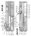
- the device shown in the drawings can be secured in the region of an upper running rail 40 of a sliding door on the ceiling 42 of a carcass.
- the housing 1 is fastened to the rear of the running rail 40.
- the running rail 40 has two guide grooves 41 for the rollers of the two sliding doors, not shown.
- a driver 6 is attached to the back of the sliding door. This driver cooperates with a sear 2 of the device.
- the sear 2 has a catch mouth 37. This catch mouth is formed by a stop arm 38 and a pressure arm 39. In the in Fig. 3 shown fishing position is the catch mouth 37 in an oblique opening position. If the sliding door is closed, the catch 6 comes against the stop arm 38 of the catch mouth 37. The catch 2 is pivoted. A locking pin 5 of the sear 2 thereby leaves a detent niche 4 of a section 14 'of a guide slot 14.
- the housing is in two parts. It has a first housing part 1 'and a second housing part 1 ", the latter forming the screw-on console with which the housing 1 is fastened to the cover 42 of the carcass
- Both housing parts 1', 1" form a guide formed by two ribs 15 for one Slider 3.
- the slider 3 has two ribs projecting in the direction of the housing part 1 ", which form between them a guide groove 16 in which the guide ribs 15 are in.
- the slider 3 has a boom on which the sear pawl 2 is pivotably mounted
- the guide pin 13 projects beyond two guide slots 14, 14 'which lie congruently to each other, wherein each of the two housing parts 1', 1 "is associated with a guide slot 14, 14 '.
- the locking pin 5 projects into the two guide slots 14, 14 '.
- the catch 2 is located outside the housing 1.
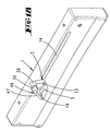
- the energy storage 7 is formed by a mounting unit.
- This mounting unit consists of a core part 10, which can be fastened with a fastening tab 33 on the housing. From the fastening tab 33 projects from a bearing pin 31.
- the bearing pin 31 is surrounded by a bearing collar 34 at a slight distance. Between bearing collar 34 and bearing pin 31, an annular bearing groove is formed.
- the bearing pin 31 extends through a bottom opening 30, which forms a bearing opening, the bottom 29 of a cup-shaped housing shell part 11.
- the pot wall is formed by an open annular wall 27. On the outer wall, the annular wall 27 has a partial circumferential ridge 28. An extension of the bottom 29 also forms a peripheral ridge 29 '.
- a scroll spring 9 This consists of a multi-wound leaf spring.
- One end 9 "of the leaf spring 9 is fastened in a fastening slot 32 of the bearing pin 31 projecting into the pot cavity
- the other end 9 'of the leaf spring 9 is fastened in a fastening slot 26 of the annular wall 27.
- the circumferential length of the outer wall of the annular wall 27 corresponds approximately to that of FIG Length of the guide slot 14.
- a pull rope 12 is attached, for example, nylon or other suitable material.
- the other end of the pull cable 12 is connected to the housing shell part 11, wherein the pull rope with several turns on the winding surface of the shell part 11 between the ribs 28, 29 'rests.
- the housing part 1 "forms a bearing cup 36, in which the housing shell part 11 is rotatably mounted.” This bearing cup supports the housing shell part 11 on the side opposite the bearing collar 35.
- the other housing part 1 ' forms a mounting pin 44 opposite the bearing cup 36, which in FIG engages a cavity of the bearing pin 31.
- a further pin 45 is provided for the rotationally fixed attachment of the fastening tab 33 on the housing part 1 '.
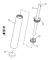
- the slide 3 has on its side opposite the boom 43 two spaced apart retaining walls 24, 25. Between the two retaining walls 24, 25, the cylinder 19 extends a pneumatic damper 8.
- a piston 21 In the cylinder 19, which is closed with a plug 20, is located a piston 21.
- the piston 21 is screwed onto one end of a piston rod 17.
- a cap 18 In the plug 20 opposite the opening of the cylinder 19, a cap 18 is screwed.
- This has a central opening which supports the piston rod 17.
- the piston 21 opposite the end of the piston rod 17 is fixedly connected to a fastening pin 23 with the housing 1.
- the piston 21 performs a relative movement relative to the cylinder 19. In this case, air flows through the piston.
- the piston has an air passage opening 22.
- the width of the air passage opening 22 determines the degree of damping. There are measures provided that increases the effective air passage opening when the slide 3 of his in the Fig. 2 illustrated end position in the in Fig. 3 shifted catch position, which is associated with the opening of the sliding door. This movement should be done undamped. A damping should be done in the opposite direction, when the energy storage discharges.
- the housing shell part 11 Since the circumference of the housing shell part 11 has a length which substantially corresponds to the length of the guide slot 14, the housing shell part 11 is rotated substantially once during the displacement of the slider 3 from the end position to the catching position.
- the preloaded roll spring 9 is only slightly further tensioned during this shift. The spring tension increases only slightly.
- the scroll spring 9 By repeatedly rotating the shell part 11 relative to the core part 10, however, the scroll spring 9 can be significantly stretched or relaxed. By these measures, the spring force of the scroll spring can be adapted to different requirements. During normal use, ie when tensioning the scroll spring in the course of opening the sliding door or when relaxing the scroll spring when closing the sliding door whose spring force changes only slightly.
- a housing half 1 has a guide slot 14 arranged near the edge of the housing, in which a guide pin 13 and a latching pin 5 of a sear 2 are guided.
- the sear 2 is located outside the housing.
- the guide slot 14 has at its end an acute-angled extension 14 ', in which the locking pin 5 can dip. This has a pivoting of the sear 2 from a driving position into a catching position result. In this position, the driver 6 a sliding door in the space between the pressure arm 39 and stop arm 38 occur.
- the pressure arm 39 is an acute-angled extension of a catch 46.
- the catch is formed by a plastic arm, which is fastened with a film hinge 48 on the catching pawl body.
- the film hinge 48 forms a leaf spring.
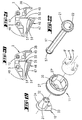
- the pressure arm 39 has a chamber 51 with a cross-section reduced chamber opening 51 '. Opposite the chamber opening 51 'is rooting on the catching pawl body 2, a tie rod 49.
- the tie rod 49 has a hammerhead head 50. In the in Fig. 21 shown manufacturing position leaves the catching pawl part 2, the injection molding machine it manufactures. In this state, the hammer head 50 is disposed outside the chamber 51.
- the leaf spring forming a film hinge 48 is relaxed. The flycatcher will then be in the in Fig. 20 brought bias position shown by the hammer head 50 is pivoted into the chamber 51.
- An inner end 9 "of the roller spring 9 inserts into a fastening slot 32 of a housing core part 10.
- An outer end 9 ' is fastened to a holding body 27' of a ring wall body 27, on the cylindrical outer surface of which a pull cable is wound.
- the Switzerlandsseil attacks a slider 3.
- This slide is guided on the housing ribs and forms the same material from the boom 43, which forms a bearing eye 52 at its free end, in which the guide pin 13 of the sear 2 is rotatably mounted.
- the slider 3 On the side facing away from the boom 43, the slider 3 is integrally formed with a pneumatic cylinder 19, which is part of a pneumatic damper 8.
- the pneumatic cylinder 19 has an opening in which the head 21 of a piston is inserted.
- the piston rod 17 has at its end a holding plate 57, which rests in a groove 56 of the wall of the housing 1. Again, the head of the piston 21 has an overflow.
- W-shaped leaf spring 53 in addition to a slide 3 material integrally formed, W-shaped leaf spring 53.
Abstract
Description
Die Erfindung betrifft eine Vorrichtung zum gedämpften Endanzug eines bewegbaren Teiles, insbesondere einer Schiebetür, eines Schubfaches oder eines anderen Möbelteils, mit einem in einem Gehäuse verschieblich angeordneten und eine Fangklinke lagernden Schieber, der vermittelst einer Rast in einer Einfangstellung zum Einfangen eines dem beweglichen Teil zugeordneten Mitnehmers gehalten ist und der nach Aufheben der Rast von der Kraft eines Kraftspeichers gedämpft von einem Dämpfungsglied in eine Endstellung verlagerbar ist.The invention relates to a device for damped Endanzug a movable part, in particular a sliding door, a drawer or other furniture part, with a slidably mounted in a housing and a satchel overlapping slide, which mediates a catch in a Einfangstellung for capturing a movable part Mitnehmers is held and is attenuated by releasing the catch of the force of an energy accumulator of a damping member in an end position.
Eine Vorrichtung der vorbezeichneten Art ist aus der
Eine ähnliche Vorrichtung, jedoch mit einem pneumatischen Dämpfer, beschreibt die
Aus dem Stand der Technik sind darüber hinaus weitere Einzugshilfen für Schubfächer oder Anzugshilfen für Schiebetüren bekannt, bei denen die Kraft zur Verlagerung des Schubfachs bzw. der Schiebetür in die Endstellung von einer gespannten Wendelgang-Zug- oder Druckfeder aufgebracht wird. Bei allen vorbekannten Lösungen besitzt der Kraftspeicher eine relativ steil verlaufende Federkennlinie. Die Anzugskraft ist zu Beginn der Bewegungseinkopplung in das zu bewegende Möbelteil groß und nimmt bis zum Erreichen der Endstellung stark ab. So beschreibt die
Der Erfindung liegt die Aufgabe zugrunde, eine gattungsgemäße Vorrichtung gebrauchsvorteilhaft weiterzubilden.The invention has for its object to further develop a generic device nutzsvorteilhaft.
Gelöst wird die Aufgabe durch die im Anspruch 1 angegebene Erfindung.The problem is solved by the invention defined in
Zunächst und im Wesentlichen ist vorgesehen, dass der Kraftspeicher eine Rollfeder aufweist. Eine Rollfeder besitzt eine Federkennlinie, die sehr schwach ansteigt. Eine Rollfeder oder eine Triebfeder besteht im Wesentlichen aus einem langen, zu einer Spirale gewickelten Federstahlband. Derartige Federn werden bei selbstwickelnden Aufrolleinrichtungen verwendet, beispielsweise bei Maßbändern oder bei Rollladengurten. Erfindungsgemäß wird eine derartige Roll- oder Triebfeder als Kraftspeicher benutzt. Dabei wickelt sich die Rollfeder bei der Verlagerung des Schiebers von der Einfangstellung bis in die Endstellung maximal nur um wenige Umdrehungen ab. Die Rollfeder steckt in einem fest mit dem Gehäuse verbundenen Kraftspeichergehäuse. Das Kraftspeichergehäüse ist zweiteilig. Es besteht aus einem Kernteil und einem Mantelteil. Das Kernteil ist fest mit dem Gehäuse verbunden. Das Mantelteil besitzt eine im Wesentlichen topfförmige Gestalt. Die Außenwandung des Topfes bildet eine Wickelzone für ein Zugseil aus. Die spiralförmig aufgewickelte Blattfeder ist mit ihrem einen Ende mit dem Kernteil verbunden. Sie kann dort in einen Schlitz eingehakt sein. Das andere Ende der Feder ist mit dem auf dem Kernteil drehbar gelagerten Mantelteil verbunden. Auch hier kann das Ende der Feder einen Haken ausbilden und in einen Schlitz der Mantelwandung des Mantelteiles eingehakt sein. Der Außendurchmesser des Mantelteiles ist in Bezug auf den Verlagerungsweg des Schiebers so gewählt, dass sich das Mantelteil im Zuge der Schieberverlagerung maximal zweimal, bevorzugt etwa nur einmal, um seine Achse dreht. Der Kraftspeicher, bestehend aus einem Gehäusekernteil und einem Gehäusemantelteil sowie aus der Rollfeder, kann als Baugruppe montiert werden. Es kann eine Montagesicherung vorgesehen sein, um den Kraftspeicher im gespannten Zustand zu montieren. Der Kraftspeicher kann nachspannbar sein. Dies erfolgt dadurch, dass das Mantelteil gegenüber dem Kernteil um mehrere, bevorzugt anderthalb Umdrehungen in Spannrichtung der Feder gedreht wird. Hierdurch erhöht sich die Anzahl der Federwindungen und damit langsam die Federkraft. Die gesamte Vorrichtung ist somit an unterschiedlich schwere Schubladen bzw. Schiebetüren anpassbar. Das Kernteil und das Mantelteil können aus Kunststoff bestehen. Das Kernteil kann einen Lagerzapfen ausbilden, der gleichzeitig ein Ende der Feder hält. Der Lagerzapfen kann eine Bodenöffnung des topfförmigen Mantelteils durchragen. An die Öffnung des Mantelteils kann sich ein Lagerkragen anschließen, der in einer Lagernut des Kernteils einliegt. Das andere Ende der Feder ist in einen Befestigungsschlitz der Ringwand des Mantelteils eingehakt. Das Kernteil kann mit einer Befestigungslasche an einem Teil des insgesamt zweiteiligen Gehäuses befestigt sein. Der Schieber kann aus Kunststoff bestehen. Der Boden bzw. die Decke des Gehäuses kann eine Führungsrippe oder mehrere Führungsrippen ausbilden, die in eine Führungsnut des Schiebers eingreifen. Das Zugseil, welches um das Gehäusemantelteil gewickelt und am Schieber befestigt ist, kann aus Nylon bestehen. Parallel zur Führung des Schiebers im Gehäuse ist ein Pneumatikdämpfer vorgesehen. Dieser besteht aus einem Zylinder, der in einer gabelförmigen Aufnahme des Schiebers einliegt. Diese Aufnahme wird von zwei voneinander beabstandeten Haltewänden ausgebildet. Die zum Pneumatikdämpfer gehörende Kolbenstange ist einseitig über einen Befestigungsstift mit dem Gehäuse verbunden. Das andere Ende der Kolbenstange trägt einen Kolben, der im Zylinder gleitend geführt ist. Der Kolben besitzt eine Luftdurchtrittsöffnung, so dass eine Dämpfung der Schieberbewegung erzeugt wird. Wesentlich ist, dass die Schieberbewegung in Anzugsrichtung gedämpft ist. Der Kolben kann so ausgebildet sein, dass bei einer Verlagerung des Schiebers in Gegenrichtung, also in Öffnungsrichtung, erheblich mehr Luft über den Kolben strömen kann, so dass in dieser Bewegungsrichtung keine oder nur eine geringe Dämpfung vorhanden ist. Die Fangklinke ist schwenkbar an einem Ausleger des Schiebers gelagert. Sie besitzt einen Führungszapfen, der in zwei kongruenten Führungsschlitzen des Gehäuses geführt ist. Die Fangklinke besitzt darüber hinaus einen Rastzapfen, der ebenfalls in dem Führungsschlitz geführt ist. Der Führungsschlitz besitzt an seinem einen Ende eine Abwinklung, die mit einer Rastnische versehen ist. In diese Rastnische tritt der Rastzapfen ein, wenn sich die Vorrichtung in ihrer Fangstellung befindet. Der Zapfen wird in diese Rastnische zwangsgesteuert, wenn die Fangklinke, von einer Schublade oder einer Schiebetür, von der Endstellung in die Fangstellung geschleppt wird. Einhergehend mit dieser Verlagerung wird der Kraftspeicher gespeichert. Die Fangklinke stellt sich in dieser Fangstellung quer, so dass ein von der Fangklinke ausgebildetes Fangmaul einen Mitnehmer, der fest mit der Tür oder der Schublade verbunden ist, einfangen kann. Der Mitnehmer schlägt dabei an einem Anschlagarm des Fangmaules an, um die Fangklinke zu verschwenken. Dabei tritt der Rastzapfen aus der Rast. Die am Zugseil wirkende Kraft des Kraftspeichers zieht den Schieber in die Endstellung und schleppt den dann im Fangmaul fest einliegenden Mitnehmer mit. In einer weiteren Variante der Erfindung ist vorgesehen, dass der das Dämpfungsglied ausbildende Zylinder materialeinheitlich mit dem Schieber verbunden ist, der innerhalb des Gehäuses längsgeführt ist. Bei dieser Ausgestaltung braucht der Zylinder keinen Deckel zu besitzen. Er besitzt aber einen materialeinheitlich angeformten Zylinderboden. Der Kolben ist mit seiner Kolbenstange am Gehäuse zugfest verankert und ragt mit seinem Kopf in den Zylinder. Der Kolben besitzt eine Luftdurchtrittsöffnung, die als Ventil ausgebildet ist. Vom Schieber kann ein Ausleger abragen, der in einem Lagerauge einen Führungszapfen der Fangklinke drehbar lagert. Ein dem Führungszapfen benachbarter Rastzapfen der Fangklinke wird in einem Führungsschlitz, der endseitig einen spitzwinklig angeordneten Rastfortsatz besitzt, geführt. Die Fangklinke besitzt einen Anschlagarm, gegen den ein an der Rückseite der Schiebetür befestigter Mitnehmer anschlägt, wenn dieser in das Fangmaul eintritt. Bei einem ordnungsgemäßen Betrieb erfolgt dies bei schrägstehender Fangklinke, so dass der Mitnehmer den zufolge der Schrägstellung zurückspringend liegenden Druckarm der Fangklinke überläuft. Beim Öffnen der Schiebetür und beim Spannen des Kraftspeichers wird eine Druckflanke, die dem Anschlagarm gegenüberliegt, vom Mitnehmer beaufschlagt. Erreicht der Mitnehmer die Raststellung, tritt der die Druckflanke bildende Druckarm zufolge eines Verschwenkens der Fangklinke aus der Bewegungsbahn des Mitnehmers. Bei einer Fehlbedienung, bei der die Fangklinke bei geöffneter Schiebetür eine der Geschlossenstellung entsprechende Endstellung einnimmt, kann der Mitnehmer trotzdem in das Fangmaul gebracht werden. Hierzu ist die Druckflanke Teil eines Schnäppers. Der Schnäpper ist ein über ein Federscharnier an der Fangklinke angelenkter Arm. Das Federscharnier bildet eine Feder. Diese ist vorgespannt. Hierzu greift ein Zuganker am Schnäpper an. Der Schnäpper kann sich gegen den Zuganker verlagern. Er besitzt eine Auflaufschräge, auf der der Mitnehmer auflaufen kann. Er überläuft dann den Schnäpper, der wieder in seine Sperrstellung zurückschnäppert, wenn der Mitnehmer die Auflaufschräge überlaufen hat. Die Fangklinke ist ein einheitliches Spritzgussteil. Der Zuganker ist materialeinheitlich mit der Fangklinke verbunden und bildet einen Hammerkopf aus, der in einer Haltekammer des Schnäppers einliegt. Der Pneumatikzylinder ist materialeinheitlich mit dem Schieber und materialeinheitlich mit einem Ausleger verbunden. Am Ende des Auslegers befindet sich ein Lagerauge, in dem ein Führungszapfen der Fangklinke geführt ist. Ein vom Führungszapfen beabstandeter Rastzapfen ist ebenfalls in einem Führungsschlitz des Gehäuses geführt. Der Führungsschlitz bildet einen spitzwinkligen Rastabschnitt aus, in dem der Rastzapfen eintreten kann. Am Schieber ist eine bogenförmige Rastfeder materialeinheitlich befestigt. Diese bildet eine erste Rastvertiefung aus, in der der Rastzapfen einliegt, wenn er sich in dem Führungsschlitz befindet. Die Rastfeder bildet eine zweite Rastvertiefung aus, in der sich der Führungszapfen befindet, wenn er sich im Rastabschnitt des Führungsschlitzes befindet. Sowohl der Schieber nebst Zylinder, angeformter Rastfeder und Auslöser als auch die Fangklinke können als einzelne Spritzgussteile aus Kunststoff gefertigt sein.First and foremost, it is provided that the energy accumulator has a scroll spring. A roll spring has a spring characteristic that rises very slightly. A scroll spring or a mainspring consists essentially of a long, wound into a spiral spring steel strip. Such springs are used in self-winding retractors, such as tape measures or roller shutter belts. According to such a rolling or mainspring is used as energy storage. In this case, the roll spring unwinds at the displacement of the slider from the Einfangstellung to the end position at most only a few turns. The scroll spring is in a power storage housing fixedly connected to the housing. The power storage housing is in two parts. It consists of a core part and a shell part. The core part is firmly connected to the housing. The shell part has a substantially cup-shaped shape. The outer wall of the pot forms a winding zone for a pull rope. The spirally wound leaf spring is connected at one end to the core part. She can be there be hooked in a slot. The other end of the spring is connected to the rotatably mounted on the core part shell part. Again, the end of the spring form a hook and be hooked into a slot of the jacket wall of the shell part. The outer diameter of the shell part is in relation chosen on the displacement path of the slider so that the shell part in the course of the slide displacement a maximum of twice, preferably only once, rotates about its axis. The energy storage, consisting of a housing core part and a housing shell part and from the scroll spring, can be mounted as an assembly. It may be provided a mounting fuse to mount the power storage in the tensioned state. The energy storage can be re-tensioned. This is done by the shell part is rotated relative to the core part by several, preferably one and a half turns in the clamping direction of the spring. This increases the number of spring coils and thus slowly the spring force. The entire device is thus adaptable to different heavy drawers or sliding doors. The core part and the shell part may be made of plastic. The core member may form a journal which simultaneously holds one end of the spring. The bearing pin can protrude through a bottom opening of the cup-shaped shell part. At the opening of the shell part, a bearing collar can be connected, which rests in a bearing groove of the core part. The other end of the spring is hooked into a mounting slot of the annular wall of the shell part. The core member may be secured to a portion of the generally two-piece housing with a fastening tab. The slide can be made of plastic. The bottom or the ceiling of the housing may form a guide rib or a plurality of guide ribs, which engage in a guide groove of the slider. The pull cable, which is wrapped around the housing shell part and attached to the slider, may be made of nylon. Parallel to the leadership of the slide in the housing, a pneumatic damper is provided. This consists of a cylinder, which rests in a fork-shaped receptacle of the slider. This receptacle is formed by two spaced apart retaining walls. The belonging to the pneumatic damper piston rod is connected on one side via a fixing pin to the housing. The other end of the piston rod carries a piston, which is slidably guided in the cylinder. The piston has an air passage opening, so that a damping of the slider movement is generated. It is essential that the slider movement dampened in the tightening direction is. The piston can be designed so that when the slide is displaced in the opposite direction, ie in the opening direction, considerably more air can flow over the piston, so that there is no or only little damping in this direction of movement. The sear is pivotally mounted on a boom of the slider. It has a guide pin, which is guided in two congruent guide slots of the housing. The squeegee also has a locking pin, which is also guided in the guide slot. The guide slot has at its one end an angled portion which is provided with a latching niche. In this detent recess of the locking pin occurs when the device is in its catch position. The pin is positively controlled in this latching niche, when the sling pawl, from a drawer or a sliding door, is dragged from the end position to the catching position. Along with this shift, the energy storage is stored. The sling pawl turns transversely in this catching position, so that a catching jaw formed by the squeezing catch can catch a catch, which is firmly connected to the door or the drawer. The driver strikes against a stop arm of the Fangmaules to pivot the sling pawl. In this case, the locking pin from the catch occurs. The force acting on the traction cable of the energy accumulator pulls the slide in the end position and travels with the then firmly entrapped in the capture mouth driver. In a further variant of the invention, it is provided that the cylinder forming the damping member is connected in the same material as the slider, which is longitudinally guided within the housing. In this embodiment, the cylinder does not need to have a lid. But he has a material integrally molded cylinder bottom. The piston is anchored with its piston rod on the housing tensile strength and protrudes with his head in the cylinder. The piston has an air passage opening, which is designed as a valve. From the slider can protrude a boom which rotatably supports a guide pin of the sear in a bearing eye. A guide pin of the adjacent detent pin of the sear is guided in a guide slot which has an acute-angled locking projection at the end. The catch has a stop arm against the a driver attached to the rear of the sliding door strikes when it enters the safety jaw. In a proper operation, this is done with inclined sear, so that the driver overflows due to the inclination receding lying pressure arm of the sear. When opening the sliding door and when tensioning the force accumulator, a pressure flank, which is opposite to the stop arm, acted upon by the driver. When the driver reaches the detent position, the pressure arm forming the pressure flank emerges from the path of movement of the driver as a result of a pivoting of the safety catch. In the case of a faulty operation in which the squeezing catch assumes an end position corresponding to the closed position when the sliding door is open, the catch can still be brought into the catching mouth. For this purpose, the pressure flank is part of a catch. The catch is a hinged by a spring hinge on the sear arm. The spring hinge forms a spring. This is preloaded. For this purpose, a tie rod attacks on the catch. The catch can shift against the tie rod. He has a ramp, on which the driver can accumulate. He then overruns the catch, which snaps back into its locked position when the driver has overrun the ramp. The satchel is a unitary injection molded part. The tie rod is materially connected to the sear and forms a hammer head, which rests in a holding chamber of the latch. The pneumatic cylinder is the same material with the slider and material unit connected to a boom. At the end of the boom is a bearing eye, in which a guide pin of the sear is guided. A distance from the guide pin locking pin is also guided in a guide slot of the housing. The guide slot forms an acute-angled locking portion, in which the locking pin can occur. On the slide an arcuate detent spring is attached the same material. This forms a first latching recess, in which the latching pin rests when it is in the guide slot. The detent spring forms a second detent recess, in which the guide pin is located when it is in the detent portion of the guide slot. Both the slide and cylinder, molded detent spring and release as well as the sear can be made as a single injection molded plastic parts.
Ausführungsbeispiele der Erfindung werden nachfolgend anhand beigefügter Zeichnungen erläutert. Es zeigen:
- Fig. 1
- eine Seitenansicht eines ersten Ausführungsbeispiels,
- Fig. 2
- eine Unteransicht des ersten Ausführungsbeispiels in der Endstellung,
- Fig. 3
- eine Darstellung gemäß
Fig. 2 in der Fangstellung, - Fig. 4
- eine Darstellung gemäß
Fig. 2 bei abgenommenem Gehäusedeckel, - Fig. 5
- eine Darstellung gemäß
Fig. 3 bei abgenommenem Gehäusedeckel, - Fig. 6
- einen Schnitt gemäß der Linie VI - VI in
Fig. 2 , - Fig. 7
- eine Explosionsdarstellung des Pneumatikdämpfungsglieds,
- Fig. 8
- eine Explosionsdarstellung des Kraftspeichers aus einer ersten Perspektive,
- Fig. 9
- eine Darstellung gemäß
Fig. 8 aus einer zweiten Perspektive, - Fig. 10
- eine perspektivische Darstellung der an einer Korpusdecke befestigten Dämpfungseinrichtung in einer Zwischenstellung,
- Fig. 11
- eine perspektivische Darstellung der Dämpfungseinrichtung in der Zwischenstellung mit abgenommener Befestigungskonsole,
- Fig. 12
- eine perspektivische Darstellung eines Gehäuseteiles,
- Fig. 13
- eine perspektivische Darstellung der einen Gehäusedeckel ausbildenden Befestigungskonsole,
- Fig. 14
- eine Darstellung gemäß
Fig. 3 eines zweiten Ausführungsbeispiels, - Fig. 15
- eine Darstellung gemäß
Fig. 2 des zweiten Ausführungsbeispiels, - Fig. 16
- eine Darstellung gemäß
Fig. 4 des zweiten Ausführungsbeispiels, - Fig. 17
- eine Darstellung gemäß
Fig. 5 des zweiten Ausführungsbeispiels, - Fig. 18
- eine perspektivische Darstellung des Gehäuseunterteils des zweiten Ausführungsbeispiels in der Fangstellung,
- Fig. 19
- eine Explosionsdarstellung des Kraftspeichers,
- Fig. 20
- die Fangklinke mit gefesseltem Schnäpper,
- Fig. 21
- die Fangklinke mit gelöstem Schnäpper,
- Fig. 22
- den Kolben,
- Fig. 23
- eine perspektivische Darstellung der Fangklinke und
- Fig. 24
- die Schieber-Zylindereinheit in perspektivischer Darstellung mit Kolben.
- Fig. 1
- a side view of a first embodiment,
- Fig. 2
- a bottom view of the first embodiment in the end position,
- Fig. 3
- a representation according to
Fig. 2 in the catch position, - Fig. 4
- a representation according to
Fig. 2 with removed housing cover, - Fig. 5
- a representation according to
Fig. 3 with removed housing cover, - Fig. 6
- a section along the line VI - VI in
Fig. 2 . - Fig. 7
- an exploded view of the pneumatic damping element,
- Fig. 8
- an exploded view of the energy storage from a first perspective,
- Fig. 9
- a representation according to
Fig. 8 from a second perspective, - Fig. 10
- a perspective view of the attached to a carcass cover damping device in an intermediate position,
- Fig. 11
- a perspective view of the damping device in the intermediate position with removed mounting bracket,
- Fig. 12
- a perspective view of a housing part,
- Fig. 13
- a perspective view of a housing cover forming mounting bracket,
- Fig. 14
- a representation according to
Fig. 3 a second embodiment, - Fig. 15
- a representation according to
Fig. 2 of the second embodiment, - Fig. 16
- a representation according to
Fig. 4 of the second embodiment, - Fig. 17
- a representation according to
Fig. 5 of the second embodiment, - Fig. 18
- a perspective view of the housing lower part of the second embodiment in the fishing position,
- Fig. 19
- an exploded view of the energy storage,
- Fig. 20
- the satchel with tied catch,
- Fig. 21
- the catch with a released catch,
- Fig. 22
- the piston,
- Fig. 23
- a perspective view of the sling and
- Fig. 24
- the slide-cylinder unit in perspective view with pistons.
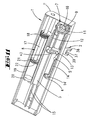
Die in den Zeichnungen dargestellte Vorrichtung kann im Bereich einer oberen Laufschiene 40 einer Schiebetür an der Decke 42 eines Korpus befestigt werden.The device shown in the drawings can be secured in the region of an upper running
Das Gehäuse 1 wird dabei rückwärtig der Laufschiene 40 befestigt. Die Laufschiene 40 besitzt zwei Führungsrinnen 41 für die Laufrollen der beiden nicht dargestellten Schiebetüren. Ein Mitnehmer 6 ist an der Rückseite der Schiebetür befestigt. Dieser Mitnehmer wirkt mit einer Fangklinke 2 der Vorrichtung zusammen. Die Fangklinke 2 besitzt ein Fangmaul 37. Dieses Fangmaul wird von einem Anschlagarm 38 und einem Druckarm 39 ausgebildet. In der in
Das Gehäuse ist zweiteilig. Es besitzt ein erstes Gehäuseteil 1' und ein zweites Gehäuseteil 1". Letzteres bildet die Anschraubkonsole, mit der das Gehäuse 1 an der Decke 42 des Korpus befestigt ist. Beide Gehäuseteile 1', 1" bilden eine von zwei Rippen 15 gebildete Führung für einen Schieber 3. Der Schieber 3 besitzt zwei in Richtung auf das Gehäuseteil 1" ragende Rippen, die zwischen sich eine Führungsnut 16 ausbilden, in der die Führungsrippen 15 einliegen. Der Schieber 3 besitzt einen Ausleger, auf dem die Fangklinke 2 schwenkbar gelagert ist. Hierzu durchgreift ein Führungszapfen 13 eine Lageröffnung des Auslegers. Der Führungszapfen 13 ragt darüber hinaus in zwei deckungsgleich zueinanderliegende Führungsschlitze 14, 14', wobei jedem der beiden Gehäuseteile 1', 1" ein Führungsschlitz 14, 14' zugeordnet ist. In die beiden Führungsschlitze 14, 14' ragt darüber hinaus auch der Rastzapfen 5. Die Fangklinke 2 befindet sich außerhalb des Gehäuses 1.The housing is in two parts. It has a
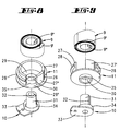
Der Kraftspeicher 7 wird von einer Montageeinheit gebildet. Diese Montageeinheit besteht aus einem Kernteil 10, welches mit einer Befestigungslasche 33 am Gehäuse befestigbar ist. Von der Befestigungslasche 33 ragt ein Lagerzapfen 31 ab. Der Lagerzapfen 31 ist mit einem geringfügigen Abstand von einem Lagerkragen 34 umgeben. Zwischen Lagerkragen 34 und Lagerzapfen 31 wird eine ringförmige Lagernut ausgebildet. Der Lagerzapfen 31 durchragt eine Bodenöffnung 30, die eine Lageröffnung ausbildet, den Boden 29 eines topfförmigen Gehäusemantelteiles 11. Die Topfwandung wird von einer offenen Ringwandung 27 ausgebildet. Auf der Außenwandung besitzt die Ringwand 27 einen Teilumfangssteg 28. Eine Verlängerung des Bodens 29 bildet ebenfalls einen Umfangssteg 29' aus. In der Höhlung, die von der Ringwand 27 umgeben ist, befindet sich eine Rollfeder 9. Diese besteht aus einer vielfach gewickelten Blattfeder. Ein Ende 9" der Blattfeder 9 ist in einem Befestigungsschlitz 32 des in die Topfhöhlung ragenden Lagerzapfens 31 befestigt. Das andere Ende 9' der Blattfeder 9 ist in einem Befestigungsschlitz 26 der Ringwand 27 befestigt. Die Umfangslänge der Außenwandung der Ringwand 27 entspricht in etwa der Länge des Führungsschlitzes 14.The
Am Schieber 3 ist ein Zugseil 12 beispielsweise aus Nylon oder einem anderen geeigneten Material befestigt. Das andere Ende des Zugseiles 12 ist mit dem Gehäusemantelteil 11 verbunden, wobei das Zugseil mit mehreren Windungen auf der Wickelfläche des Mantelteiles 11 zwischen den Rippen 28, 29' aufliegt.On the
Das Gehäuseteil 1" bildet einen Lagertopf 36 aus, in dem das Gehäusemantelteil 11 drehbar gelagert ist. Dieser Lagertopf lagert das Gehäusemantelteil 11 an der dem Lagerkragen 35 gegenüberliegenden Seite. Das andere Gehäuseteil 1' bildet einen dem Lagertopf 36 gegenüberliegenden Befestigungszapfen 44 aus, der in eine Höhlung des Lagerzapfens 31 eingreift. Zur drehfesten Befestigung der Befestigungslasche 33 am Gehäuseteil 1' ist ein weiterer Zapfen 45 vorgesehen.The
Der Schieber 3 besitzt auf seiner dem Ausleger 43 gegenüberliegenden Seite zwei voneinander beabstandete Haltewände 24, 25. Zwischen den beiden Haltewänden 24, 25 erstreckt sich der Zylinder 19 eines Pneumatikdämpfers 8. In dem Zylinder 19, der mit einem Stopfen 20 verschlossen ist, befindet sich ein Kolben 21. Der Kolben 21 ist auf ein Ende einer Kolbenstange 17 aufgeschraubt. In die dem Stopfen 20 gegenüberliegende Öffnung des Zylinders 19 ist eine Verschlusskappe 18 eingeschraubt. Diese besitzt eine zentrale Öffnung, welche die Kolbenstange 17 lagert. Das dem Kolben 21 gegenüberliegende Ende der Kolbenstange 17 ist mit einem Befestigungsstift 23 fest mit dem Gehäuse 1 verbunden. Während der Verlagerung des Schiebers 3 gegenüber dem Gehäuse 1 vollzieht der Kolben 21 eine Relativbewegung gegenüber dem Zylinder 19. Dabei durchströmt Luft den Kolben. Hierzu besitzt der Kolben eine Luftdurchtrittsöffnung 22. Die Weite der Luftdurchtrittsöffnung 22 bestimmt den Dämpfungsgrad. Es sind Maßnahmen vorgesehen, dass sich die wirksame Luftdurchtrittsöffnung vergrößert, wenn der Schieber 3 von seiner in der
Da der Umfang des Gehäusemantelteiles 11 eine Länge besitzt, die im Wesentlichen der Länge des Führungsschlitzes 14 entspricht, wird das Gehäusemantelteil 11 bei der Verlagerung des Schiebers 3 von der Endstellung in die Fangstellung im Wesentlichen einmal gedreht. Die vorgespannte Rollfeder 9 wird bei dieser Verlagerung nur geringfügig weitergespannt. Dabei steigt die Federspannung nur geringfügig an.Since the circumference of the
Durch mehrmaliges Drehen des Mantelteils 11 gegenüber dem Kernteil 10 kann die Rollfeder 9 jedoch signifikant gespannt bzw. entspannt werden. Durch diese Maßnahmen kann die Federkraft der Rollfeder an unterschiedliche Anforderungen angepasst werden. Während des bestimmungsgemäßen Gebrauchs, also beim Spannen der Rollfeder im Zuge des Öffnens der Schiebetür oder beim Entspannen der Rollfeder beim Schließen der Schiebetür ändert sich deren Federkraft aber nur geringfügig.By repeatedly rotating the
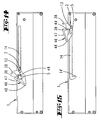
Bei dem in den
Bei diesem Ausführungsbeispiel ist der Druckarm 39 ein spitzwinkliger Fortsatz eines Schnäppers 46. Der Schnäpper wird von einem Kunststoffarm ausgebildet, der mit einem Filmscharnier 48 am Fangklinkenkörper befestigt ist. Das Filmscharnier 48 bildet eine Blattfeder. Der Druckarm 39 besitzt eine Kammer 51 mit einer querschnittsverminderten Kammeröffnung 51'. Gegenüberliegend der Kammeröffnung 51' wurzelt am Fangklinkenkörper 2 ein Zuganker 49. Der Zuganker 49 besitzt einen hammerkopfförmigen Kopf 50. In der in
In der in
Ein inneres Ende 9" der Rollenfeder 9 steckt dabei in einen Befestigungsschlitz 32 eines Gehäusekernteiles 10 ein. Ein äußeres Ende 9' ist an einem Haltekörper 27' eines Ringwandkörpers 27 befestigt, auf dessen zylinderförmiger Außenfläche ein Zugseil aufgewickelt ist.An
Das Zugsseil greift an einem Schieber 3 an. Dieser Schieber ist auf Gehäuserippen geführt und bildet materialeinheitlich den Ausleger 43 aus, der an seinem freien Ende ein Lagerauge 52 ausbildet, in welchem der Führungszapfen 13 der Fangklinke 2 drehbeweglich gelagert ist. Auf der vom Ausleger 43 wegweisenden Seite ist dem Schieber 3 materialeinheitlich ein Pneumatikzylinder 19 angeformt, der Teil eines Pneumatikdämpfers 8 ist. Der Pneumatikzylinder 19 besitzt eine Öffnung, in der der Kopf 21 eines Kolbens steckt. Die Kolbenstange 17 besitzt an ihrem Ende eine Halteplatte 57, die in einer Nut 56 der Wandung des Gehäuses 1 einliegt. Auch hier besitzt der Kopf des Kolbens 21 eine Überströmöffnung.The Zugsseil attacks a
Hervorzuheben bei diesem Ausführungsbeispiel ist darüber hinaus eine am Schieber 3 materialeinheitlich angeformte, W-förmige Blattfeder 53. Diese bildet eine Rastfeder aus. Sie besitzt zwei voneinander entfernte Rastvertiefungen 54 und 55. In diesen Rastvertiefungen 54 und 55 befindet sich in jeweils einer der beiden Betriebsstellungen der Rastzapfen 5. In der in
Claims (12)
- A device for damped end closing of a movable part, in particular a sliding door, a drawer or another furniture component, the device comprising a slide (3) that is displaceably disposed in a housing (1) and has mounted on it a catching pawl (3), the slide being held in a capturing position by means of a latch (4, 5) in order to capture a drive member (6) which is associated with the movable part, and the slide being displaceable into an end position by the force of an energy storage mechanism (7), damped by a damping member (8), when the latch (4, 5) is released, characterized in that the energy storage mechanism (7) has a scroll spring (9) which is mounted by an energy storage mechanism housing that has a core part (10) which is fixedly connected to the housing (1) and a sleeve part (11) which is rotatably mounted on the core part, the slide (3) being connected to the energy storage mechanism (7) by a pull wire (12) that is wound up on the sleeve part (11).
- A device according to Claim 1, characterized in that the core part (10) is secured to the housing (1) by a mounting tongue (33).
- A device according to either of the preceding claims, characterized in that the sleeve part (11) is cup-shaped and has a bearing collar (35) that adjoins a bearing opening (30) in the cup-base (29), the collar (35) being enclosed in a bearing groove formed by a bearing collar (34) of the core part (10).
- A device according to any of the preceding claims, characterized in that the scroll spring (9) is held by a first hook end (9") in a securing slot (32) of a bearing pin (31) of the core part (10) and by a second end (9') in a securing slot (26) of an annular wall (27, 27') of the sleeve part (11) .
- A device according to any of the preceding claims, characterized by circumferential webs (28, 29') located on the periphery of the sleeve part (11).
- A device according to any of the preceding claims, characterized in that the slide (3) is displaceably mounted on one or more guide ribs (15) of a housing part (1', 1") by means of a guide groove (16).
- A device according to any of the preceding claims, characterized in that a pneumatic damper (8) forming the damping member has a cylinder (19), in which there is disposed a piston (21) that is secured to the end of a piston rod (17).
- A device according to Claim 7, characterized in that the cylinder (19) is located between two retaining walls (24, 25) of the slide (3) and the piston rod (17) is secured to the housing (1).
- A device according to any of the preceding claims, characterized in that the capturing pawl (2) has a pressure flank (39), which is formed by a latch member (46).
- A device according to Claim 9, characterized in that the latch member (46) has a spring which is formed by a film hinge (48) and is held in a preloaded position by means of a pull rod (49).
- A device according to any of Claims 7 to 10, characterized in that the cylinder (19) and the slide (3) form a single integral unit.
- A device according to any of the preceding claims, characterized by a latch spring (53), which is formed on the slide, for the purpose of fixing a latching pin (5) of the capturing pawl (2) in a respective one of two latching positions (54, 55).
Applications Claiming Priority (1)
| Application Number | Priority Date | Filing Date | Title |
|---|---|---|---|
| DE102007009076A DE102007009076A1 (en) | 2007-02-23 | 2007-02-23 | Damping device for movable furniture parts |
Publications (2)
| Publication Number | Publication Date |
|---|---|
| EP1961332A1 EP1961332A1 (en) | 2008-08-27 |
| EP1961332B1 true EP1961332B1 (en) | 2011-04-20 |
Family
ID=39420518
Family Applications (1)
| Application Number | Title | Priority Date | Filing Date |
|---|---|---|---|
| EP08151739A Not-in-force EP1961332B1 (en) | 2007-02-23 | 2008-02-21 | Damping device for movable furniture parts |
Country Status (3)
| Country | Link |
|---|---|
| EP (1) | EP1961332B1 (en) |
| AT (1) | ATE505976T1 (en) |
| DE (2) | DE102007009076A1 (en) |
Families Citing this family (17)
| Publication number | Priority date | Publication date | Assignee | Title |
|---|---|---|---|---|
| MX2007005260A (en) * | 2004-11-05 | 2007-07-09 | Accuride Int Inc | Dampened movement mechanism and slide incorporating the same. |
| DE202008000932U1 (en) * | 2008-01-22 | 2009-05-28 | Hettich-Heinze Gmbh & Co. Kg | Damping device for movable furniture parts |
| DE102008051360A1 (en) * | 2008-10-15 | 2010-05-12 | Karl Simon Gmbh & Co. Kg | retraction device |
| CN101810404B (en) * | 2009-02-20 | 2011-10-19 | 李绍汉 | Drawer buffer |
| DE202009002715U1 (en) * | 2009-02-25 | 2010-07-15 | Paul Hettich Gmbh & Co. Kg | Pull-out guide for a furniture pull-out part |
| DE202009011042U1 (en) | 2009-08-13 | 2010-12-30 | Weber & Co. Gmbh Kg | sliding door hardware |
| DE202009014882U1 (en) * | 2009-12-18 | 2011-05-05 | Hettich-Heinze Gmbh & Co. Kg | Hardware fitting for two sliding door leaves |
| DE102010000341A1 (en) * | 2010-02-08 | 2011-08-11 | Karl Simon GmbH & Co. KG, 78733 | Feeding device for furniture |
| DE102010000340C5 (en) * | 2010-02-08 | 2019-12-05 | Karl Simon Gmbh & Co. Kg | Pulling device and arrangement for sliding doors and a method for operating a sliding door |
| DE202010008860U1 (en) * | 2010-10-21 | 2012-01-23 | Hücking GmbH | Fitting system for sliding doors |
| DE102010061160B4 (en) * | 2010-12-10 | 2023-10-26 | Hettich-Heinze Gmbh & Co. Kg | Closing and damping device for movable furniture parts |
| DE102011115662B4 (en) * | 2011-09-28 | 2013-04-25 | Door & Window Hardware Co. | Adjustable automatic reset device with buffer effect for a sliding door |
| DE102015203812B4 (en) * | 2015-03-03 | 2020-11-12 | Hahn-Gasfedern Gmbh | Spring and / or damper element |
| US10294706B2 (en) | 2016-06-30 | 2019-05-21 | Rollmech Automotive Sanayi Ve Ticaret Anonim Sirketi | Sliding door stopper |
| JP6962567B2 (en) * | 2018-04-26 | 2021-11-05 | 日本アキュライド株式会社 | Slide rail with automatic pull-in device |
| CN112353152B (en) * | 2020-11-16 | 2022-08-05 | 湖州品创孵化器有限公司 | Metal furniture bolt hole body structure |
| AT526130A1 (en) * | 2022-04-29 | 2023-11-15 | Blum Gmbh Julius | Arrangement for guiding at least one movable furniture part relative to a furniture body |
Family Cites Families (13)
| Publication number | Priority date | Publication date | Assignee | Title |
|---|---|---|---|---|
| US4004372A (en) * | 1975-04-14 | 1977-01-25 | Doormaid, Inc. | Sliding door closer and method and apparatus for installing the same |
| JPH0270879A (en) | 1988-09-06 | 1990-03-09 | Sankyo Seiki Mfg Co Ltd | Door closer |
| AU2003212079A1 (en) * | 2002-03-21 | 2003-10-08 | Julius Blum Gesellschaft M.B.H. | Pneumatic braking and damping device, particularly for movable furniture parts |
| DE20218927U1 (en) * | 2002-12-05 | 2003-02-13 | Hettich Heinze Gmbh & Co Kg | Damping and retraction device for sliding doors |
| WO2005044046A1 (en) | 2003-01-10 | 2005-05-19 | Alfit Ag | Automatic retraction mechanism for drawer pull-out guides |
| EP1622486A4 (en) | 2003-05-13 | 2009-02-25 | Grass Gmbh | Drawer closing mechanism |
| JP3930459B2 (en) | 2003-06-30 | 2007-06-13 | 株式会社シモダイラ | Sliding door closing device |
| DE20315124U1 (en) | 2003-09-29 | 2004-02-26 | Hettich-Heinze Gmbh & Co. Kg | Sliding support system and movement damping system for movable part of piece of furniture has tongue on bracket engaging jaws connected to spring and damper unit in fixed part |
| DE102004038708A1 (en) | 2004-08-10 | 2006-03-09 | Schock Metallwerk Gmbh | Movement damping device |
| DE202004018970U1 (en) | 2004-12-08 | 2005-02-03 | Hettich-Heinze Gmbh & Co. Kg | Excerpt, in particular heavy-duty drawer with at least one sliding element |
| DE102005010226A1 (en) * | 2005-03-05 | 2006-03-30 | Daimlerchrysler Ag | Drawer is fed into drawer space with temperature-dependent drive force and is movable by the effect of a roller spring |
| DE202005006931U1 (en) | 2005-04-28 | 2006-08-31 | Hettich-Heinze Gmbh & Co. Kg | Damping device for movable furniture parts |
| DE102005038727A1 (en) * | 2005-08-15 | 2007-02-22 | Miele & Cie. Kg | Washing machine with detergent and detergent drawer with the closing or opening movement supporting means |
-
2007
- 2007-02-23 DE DE102007009076A patent/DE102007009076A1/en not_active Ceased
-
2008
- 2008-02-21 DE DE502008003237T patent/DE502008003237D1/en active Active
- 2008-02-21 EP EP08151739A patent/EP1961332B1/en not_active Not-in-force
- 2008-02-21 AT AT08151739T patent/ATE505976T1/en active
Also Published As
| Publication number | Publication date |
|---|---|
| ATE505976T1 (en) | 2011-05-15 |
| DE102007009076A1 (en) | 2008-08-28 |
| EP1961332A1 (en) | 2008-08-27 |
| DE502008003237D1 (en) | 2011-06-01 |
Similar Documents
| Publication | Publication Date | Title |
|---|---|---|
| EP1961332B1 (en) | Damping device for movable furniture parts | |
| EP2948023B1 (en) | Accelerating device for moveable furniture or domestic-appliance parts | |
| AT509923B1 (en) | FEEDING DEVICE FOR PULLING A MOVABLE FURNITURE PART | |
| DE10253138B4 (en) | Door device for a vehicle and method for controlling movement of a door | |
| DE102010051518B4 (en) | Door lock for a household electrical appliance | |
| EP0985847A2 (en) | Device for limiting force | |
| WO2009076785A1 (en) | Device for pulling a sliding door into the end position and damping said door, the same being supported by traveling gears and guided in a profile rail | |
| EP2088229B1 (en) | Sewing machine and winding device for such a sewing machine | |
| WO2016037919A1 (en) | Device for winding up a cable | |
| EP2335476B1 (en) | Braking device for a rope roll of a mechanical retractable and uncoilable lead for animals | |
| DE202009005255U1 (en) | ratcheting | |
| EP3013187A1 (en) | Retraction device, extension guide having a retraction device and furniture having an extension guide | |
| DE4015404A1 (en) | Pipe clamp with curved band - which has two end flanges, has elastic inner lining, and tension screw and counter plate | |
| EP2309086A1 (en) | Holding element for adjusting a cover of a piece of furniture | |
| DE20318929U1 (en) | Automatic retraction mechanism, for a furniture sliding drawer, has a structured head at the end of the piston rod as a connecting link with a holder at the sprung pawl without an additional damper spring | |
| DE202005016007U1 (en) | Reel is for incorporation is fishing rod and is for winding fishing line on and off, having device for fixing line longitudinally | |
| DE102010038247A1 (en) | Locking system for pull-out furniture part of furniture, is provided with housing slidably mounted on driver of retraction device, where activator is coupled to furniture part | |
| DE102014218019B3 (en) | Device for winding a cable | |
| DE102009012921A1 (en) | Device or furniture has body, drawer which is pulled out from body, and move-in mechanism for moving-in drawer in body, where guide path is provided at body or at drawer | |
| EP2138621B1 (en) | Sewing machine and spool device for operating such a sewing machine | |
| DE102006056791A1 (en) | Spring joint for connecting two components, has runner, guiding body for guiding runner and spring element which is fixed to guiding body whereby runner in stand by position can be fixed indirectly by free spring end | |
| DE3722604C2 (en) | Turning device for Roman blinds | |
| EP3675691A1 (en) | Retraction device for retracting a movable part of an item of furniture or domestic appliance into an end position | |
| CH713355A2 (en) | Bearing part for a cloth roller of a weather protection device. | |
| DE102016121609A1 (en) | retractor |
Legal Events
| Date | Code | Title | Description |
|---|---|---|---|
| PUAI | Public reference made under article 153(3) epc to a published international application that has entered the european phase |
Free format text: ORIGINAL CODE: 0009012 |
|
| AK | Designated contracting states |
Kind code of ref document: A1 Designated state(s): AT BE BG CH CY CZ DE DK EE ES FI FR GB GR HR HU IE IS IT LI LT LU LV MC MT NL NO PL PT RO SE SI SK TR |
|
| AX | Request for extension of the european patent |
Extension state: AL BA MK RS |
|
| 17P | Request for examination filed |
Effective date: 20090226 |
|
| 17Q | First examination report despatched |
Effective date: 20090331 |
|
| AKX | Designation fees paid |
Designated state(s): AT BE BG CH CY CZ DE DK EE ES FI FR GB GR HR HU IE IS IT LI LT LU LV MC MT NL NO PL PT RO SE SI SK TR |
|
| GRAP | Despatch of communication of intention to grant a patent |
Free format text: ORIGINAL CODE: EPIDOSNIGR1 |
|
| GRAS | Grant fee paid |
Free format text: ORIGINAL CODE: EPIDOSNIGR3 |
|
| GRAA | (expected) grant |
Free format text: ORIGINAL CODE: 0009210 |
|
| AK | Designated contracting states |
Kind code of ref document: B1 Designated state(s): AT BE BG CH CY CZ DE DK EE ES FI FR GB GR HR HU IE IS IT LI LT LU LV MC MT NL NO PL PT RO SE SI SK TR |
|
| REG | Reference to a national code |
Ref country code: GB Ref legal event code: FG4D Free format text: NOT ENGLISH |
|
| REG | Reference to a national code |
Ref country code: CH Ref legal event code: EP |
|
| REG | Reference to a national code |
Ref country code: IE Ref legal event code: FG4D Free format text: LANGUAGE OF EP DOCUMENT: GERMAN |
|
| REF | Corresponds to: |
Ref document number: 502008003237 Country of ref document: DE Date of ref document: 20110601 Kind code of ref document: P |
|
| REG | Reference to a national code |
Ref country code: DE Ref legal event code: R096 Ref document number: 502008003237 Country of ref document: DE Effective date: 20110601 |
|
| REG | Reference to a national code |
Ref country code: NL Ref legal event code: VDEP Effective date: 20110420 |
|
| LTIE | Lt: invalidation of european patent or patent extension |
Effective date: 20110420 |
|
| PG25 | Lapsed in a contracting state [announced via postgrant information from national office to epo] |
Ref country code: PT Free format text: LAPSE BECAUSE OF FAILURE TO SUBMIT A TRANSLATION OF THE DESCRIPTION OR TO PAY THE FEE WITHIN THE PRESCRIBED TIME-LIMIT Effective date: 20110822 Ref country code: SE Free format text: LAPSE BECAUSE OF FAILURE TO SUBMIT A TRANSLATION OF THE DESCRIPTION OR TO PAY THE FEE WITHIN THE PRESCRIBED TIME-LIMIT Effective date: 20110420 Ref country code: NO Free format text: LAPSE BECAUSE OF FAILURE TO SUBMIT A TRANSLATION OF THE DESCRIPTION OR TO PAY THE FEE WITHIN THE PRESCRIBED TIME-LIMIT Effective date: 20110720 Ref country code: LT Free format text: LAPSE BECAUSE OF FAILURE TO SUBMIT A TRANSLATION OF THE DESCRIPTION OR TO PAY THE FEE WITHIN THE PRESCRIBED TIME-LIMIT Effective date: 20110420 Ref country code: HR Free format text: LAPSE BECAUSE OF FAILURE TO SUBMIT A TRANSLATION OF THE DESCRIPTION OR TO PAY THE FEE WITHIN THE PRESCRIBED TIME-LIMIT Effective date: 20110420 |
|
| REG | Reference to a national code |
Ref country code: IE Ref legal event code: FD4D |
|
| PG25 | Lapsed in a contracting state [announced via postgrant information from national office to epo] |
Ref country code: CY Free format text: LAPSE BECAUSE OF FAILURE TO SUBMIT A TRANSLATION OF THE DESCRIPTION OR TO PAY THE FEE WITHIN THE PRESCRIBED TIME-LIMIT Effective date: 20110420 Ref country code: ES Free format text: LAPSE BECAUSE OF FAILURE TO SUBMIT A TRANSLATION OF THE DESCRIPTION OR TO PAY THE FEE WITHIN THE PRESCRIBED TIME-LIMIT Effective date: 20110731 Ref country code: FI Free format text: LAPSE BECAUSE OF FAILURE TO SUBMIT A TRANSLATION OF THE DESCRIPTION OR TO PAY THE FEE WITHIN THE PRESCRIBED TIME-LIMIT Effective date: 20110420 Ref country code: IS Free format text: LAPSE BECAUSE OF FAILURE TO SUBMIT A TRANSLATION OF THE DESCRIPTION OR TO PAY THE FEE WITHIN THE PRESCRIBED TIME-LIMIT Effective date: 20110820 Ref country code: SI Free format text: LAPSE BECAUSE OF FAILURE TO SUBMIT A TRANSLATION OF THE DESCRIPTION OR TO PAY THE FEE WITHIN THE PRESCRIBED TIME-LIMIT Effective date: 20110420 Ref country code: LV Free format text: LAPSE BECAUSE OF FAILURE TO SUBMIT A TRANSLATION OF THE DESCRIPTION OR TO PAY THE FEE WITHIN THE PRESCRIBED TIME-LIMIT Effective date: 20110420 |
|
| PG25 | Lapsed in a contracting state [announced via postgrant information from national office to epo] |
Ref country code: NL Free format text: LAPSE BECAUSE OF FAILURE TO SUBMIT A TRANSLATION OF THE DESCRIPTION OR TO PAY THE FEE WITHIN THE PRESCRIBED TIME-LIMIT Effective date: 20110420 |
|
| PG25 | Lapsed in a contracting state [announced via postgrant information from national office to epo] |
Ref country code: EE Free format text: LAPSE BECAUSE OF FAILURE TO SUBMIT A TRANSLATION OF THE DESCRIPTION OR TO PAY THE FEE WITHIN THE PRESCRIBED TIME-LIMIT Effective date: 20110420 Ref country code: CZ Free format text: LAPSE BECAUSE OF FAILURE TO SUBMIT A TRANSLATION OF THE DESCRIPTION OR TO PAY THE FEE WITHIN THE PRESCRIBED TIME-LIMIT Effective date: 20110420 Ref country code: IE Free format text: LAPSE BECAUSE OF FAILURE TO SUBMIT A TRANSLATION OF THE DESCRIPTION OR TO PAY THE FEE WITHIN THE PRESCRIBED TIME-LIMIT Effective date: 20110420 |
|
| PLBE | No opposition filed within time limit |
Free format text: ORIGINAL CODE: 0009261 |
|
| STAA | Information on the status of an ep patent application or granted ep patent |
Free format text: STATUS: NO OPPOSITION FILED WITHIN TIME LIMIT |
|
| PG25 | Lapsed in a contracting state [announced via postgrant information from national office to epo] |
Ref country code: SK Free format text: LAPSE BECAUSE OF FAILURE TO SUBMIT A TRANSLATION OF THE DESCRIPTION OR TO PAY THE FEE WITHIN THE PRESCRIBED TIME-LIMIT Effective date: 20110420 Ref country code: DK Free format text: LAPSE BECAUSE OF FAILURE TO SUBMIT A TRANSLATION OF THE DESCRIPTION OR TO PAY THE FEE WITHIN THE PRESCRIBED TIME-LIMIT Effective date: 20110420 Ref country code: PL Free format text: LAPSE BECAUSE OF FAILURE TO SUBMIT A TRANSLATION OF THE DESCRIPTION OR TO PAY THE FEE WITHIN THE PRESCRIBED TIME-LIMIT Effective date: 20110420 Ref country code: RO Free format text: LAPSE BECAUSE OF FAILURE TO SUBMIT A TRANSLATION OF THE DESCRIPTION OR TO PAY THE FEE WITHIN THE PRESCRIBED TIME-LIMIT Effective date: 20110420 |
|
| 26N | No opposition filed |
Effective date: 20120123 |
|
| REG | Reference to a national code |
Ref country code: DE Ref legal event code: R097 Ref document number: 502008003237 Country of ref document: DE Effective date: 20120123 |
|
| PG25 | Lapsed in a contracting state [announced via postgrant information from national office to epo] |
Ref country code: IT Free format text: LAPSE BECAUSE OF FAILURE TO SUBMIT A TRANSLATION OF THE DESCRIPTION OR TO PAY THE FEE WITHIN THE PRESCRIBED TIME-LIMIT Effective date: 20110420 |
|
| BERE | Be: lapsed |
Owner name: WEBER & CO. G.M.B.H. KG Effective date: 20120228 |
|
| PG25 | Lapsed in a contracting state [announced via postgrant information from national office to epo] |
Ref country code: MC Free format text: LAPSE BECAUSE OF NON-PAYMENT OF DUE FEES Effective date: 20120229 |
|
| REG | Reference to a national code |
Ref country code: CH Ref legal event code: PL |
|
| GBPC | Gb: european patent ceased through non-payment of renewal fee |
Effective date: 20120221 |
|
| PG25 | Lapsed in a contracting state [announced via postgrant information from national office to epo] |
Ref country code: LI Free format text: LAPSE BECAUSE OF NON-PAYMENT OF DUE FEES Effective date: 20120229 Ref country code: CH Free format text: LAPSE BECAUSE OF NON-PAYMENT OF DUE FEES Effective date: 20120229 |
|
| REG | Reference to a national code |
Ref country code: FR Ref legal event code: ST Effective date: 20121031 |
|
| PG25 | Lapsed in a contracting state [announced via postgrant information from national office to epo] |
Ref country code: BE Free format text: LAPSE BECAUSE OF NON-PAYMENT OF DUE FEES Effective date: 20120228 |
|
| PG25 | Lapsed in a contracting state [announced via postgrant information from national office to epo] |
Ref country code: GB Free format text: LAPSE BECAUSE OF NON-PAYMENT OF DUE FEES Effective date: 20120221 Ref country code: FR Free format text: LAPSE BECAUSE OF NON-PAYMENT OF DUE FEES Effective date: 20120229 |
|
| PG25 | Lapsed in a contracting state [announced via postgrant information from national office to epo] |
Ref country code: BG Free format text: LAPSE BECAUSE OF FAILURE TO SUBMIT A TRANSLATION OF THE DESCRIPTION OR TO PAY THE FEE WITHIN THE PRESCRIBED TIME-LIMIT Effective date: 20110720 |
|
| PG25 | Lapsed in a contracting state [announced via postgrant information from national office to epo] |
Ref country code: MT Free format text: LAPSE BECAUSE OF FAILURE TO SUBMIT A TRANSLATION OF THE DESCRIPTION OR TO PAY THE FEE WITHIN THE PRESCRIBED TIME-LIMIT Effective date: 20110420 |
|
| REG | Reference to a national code |
Ref country code: DE Ref legal event code: R082 Ref document number: 502008003237 Country of ref document: DE Representative=s name: KOHLER SCHMID MOEBUS PATENTANWAELTE, DE Ref country code: DE Ref legal event code: R082 Ref document number: 502008003237 Country of ref document: DE Representative=s name: KOHLER SCHMID MOEBUS PATENTANWAELTE PARTNERSCH, DE |
|
| REG | Reference to a national code |
Ref country code: AT Ref legal event code: MM01 Ref document number: 505976 Country of ref document: AT Kind code of ref document: T Effective date: 20130221 |
|
| PG25 | Lapsed in a contracting state [announced via postgrant information from national office to epo] |
Ref country code: TR Free format text: LAPSE BECAUSE OF FAILURE TO SUBMIT A TRANSLATION OF THE DESCRIPTION OR TO PAY THE FEE WITHIN THE PRESCRIBED TIME-LIMIT Effective date: 20110420 |
|
| PG25 | Lapsed in a contracting state [announced via postgrant information from national office to epo] |
Ref country code: LU Free format text: LAPSE BECAUSE OF NON-PAYMENT OF DUE FEES Effective date: 20120221 Ref country code: AT Free format text: LAPSE BECAUSE OF NON-PAYMENT OF DUE FEES Effective date: 20130221 |
|
| PG25 | Lapsed in a contracting state [announced via postgrant information from national office to epo] |
Ref country code: HU Free format text: LAPSE BECAUSE OF FAILURE TO SUBMIT A TRANSLATION OF THE DESCRIPTION OR TO PAY THE FEE WITHIN THE PRESCRIBED TIME-LIMIT Effective date: 20080221 |
|
| PG25 | Lapsed in a contracting state [announced via postgrant information from national office to epo] |
Ref country code: GR Free format text: LAPSE BECAUSE OF FAILURE TO SUBMIT A TRANSLATION OF THE DESCRIPTION OR TO PAY THE FEE WITHIN THE PRESCRIBED TIME-LIMIT Effective date: 20110420 |
|
| REG | Reference to a national code |
Ref country code: DE Ref legal event code: R079 Ref document number: 502008003237 Country of ref document: DE Free format text: PREVIOUS MAIN CLASS: A47B0088040000 Ipc: A47B0088400000 |
|
| REG | Reference to a national code |
Ref country code: DE Ref legal event code: R082 Ref document number: 502008003237 Country of ref document: DE Representative=s name: KOHLER SCHMID MOEBUS PATENTANWAELTE PARTNERSCH, DE Ref country code: DE Ref legal event code: R081 Ref document number: 502008003237 Country of ref document: DE Owner name: SLIDING COMPETENCE CENTER KFT., HU Free format text: FORMER OWNER: WEBER & CO. GMBH KG, 42551 VELBERT, DE |
|
| PGFP | Annual fee paid to national office [announced via postgrant information from national office to epo] |
Ref country code: DE Payment date: 20190227 Year of fee payment: 12 |
|
| REG | Reference to a national code |
Ref country code: DE Ref legal event code: R119 Ref document number: 502008003237 Country of ref document: DE |
|
| PG25 | Lapsed in a contracting state [announced via postgrant information from national office to epo] |
Ref country code: DE Free format text: LAPSE BECAUSE OF NON-PAYMENT OF DUE FEES Effective date: 20200901 |
|
| P01 | Opt-out of the competence of the unified patent court (upc) registered |
Effective date: 20230630 |