EP1959859B1 - Handteil einer elektrischen zahnbürste - Google Patents
Handteil einer elektrischen zahnbürste Download PDFInfo
- Publication number
- EP1959859B1 EP1959859B1 EP06791606.4A EP06791606A EP1959859B1 EP 1959859 B1 EP1959859 B1 EP 1959859B1 EP 06791606 A EP06791606 A EP 06791606A EP 1959859 B1 EP1959859 B1 EP 1959859B1
- Authority
- EP
- European Patent Office
- Prior art keywords
- housing
- cover
- handle according
- edge
- catch
- Prior art date
- Legal status (The legal status is an assumption and is not a legal conclusion. Google has not performed a legal analysis and makes no representation as to the accuracy of the status listed.)
- Active
Links
- 230000008878 coupling Effects 0.000 claims description 16
- 238000010168 coupling process Methods 0.000 claims description 16
- 238000005859 coupling reaction Methods 0.000 claims description 16
- 238000007789 sealing Methods 0.000 claims description 7
- 238000003780 insertion Methods 0.000 claims description 4
- 230000037431 insertion Effects 0.000 claims description 4
- 230000000630 rising effect Effects 0.000 claims description 4
- 239000007788 liquid Substances 0.000 claims description 2
- 238000009412 basement excavation Methods 0.000 description 11
- 230000000295 complement effect Effects 0.000 description 3
- 238000002347 injection Methods 0.000 description 3
- 239000007924 injection Substances 0.000 description 3
- 238000004140 cleaning Methods 0.000 description 2
- 230000000694 effects Effects 0.000 description 2
- 239000007787 solid Substances 0.000 description 2
- 230000001154 acute effect Effects 0.000 description 1
- 230000015572 biosynthetic process Effects 0.000 description 1
- 230000001680 brushing effect Effects 0.000 description 1
- 238000006243 chemical reaction Methods 0.000 description 1
- 230000001419 dependent effect Effects 0.000 description 1
- 230000009977 dual effect Effects 0.000 description 1
- 230000005489 elastic deformation Effects 0.000 description 1
- 238000011086 high cleaning Methods 0.000 description 1
- 230000008676 import Effects 0.000 description 1
- 238000001746 injection moulding Methods 0.000 description 1
- 239000000463 material Substances 0.000 description 1
- 239000006223 plastic coating Substances 0.000 description 1
- 230000000284 resting effect Effects 0.000 description 1
Images

Classifications
-
- A—HUMAN NECESSITIES
- A61—MEDICAL OR VETERINARY SCIENCE; HYGIENE
- A61C—DENTISTRY; APPARATUS OR METHODS FOR ORAL OR DENTAL HYGIENE
- A61C17/00—Devices for cleaning, polishing, rinsing or drying teeth, teeth cavities or prostheses; Saliva removers; Dental appliances for receiving spittle
- A61C17/16—Power-driven cleaning or polishing devices
- A61C17/22—Power-driven cleaning or polishing devices with brushes, cushions, cups, or the like
- A61C17/225—Handles or details thereof
-
- A—HUMAN NECESSITIES
- A61—MEDICAL OR VETERINARY SCIENCE; HYGIENE
- A61C—DENTISTRY; APPARATUS OR METHODS FOR ORAL OR DENTAL HYGIENE
- A61C17/00—Devices for cleaning, polishing, rinsing or drying teeth, teeth cavities or prostheses; Saliva removers; Dental appliances for receiving spittle
- A61C17/16—Power-driven cleaning or polishing devices
- A61C17/22—Power-driven cleaning or polishing devices with brushes, cushions, cups, or the like
- A61C17/224—Electrical recharging arrangements
Definitions
- the present invention relates to a handpiece of an electric toothbrush with a housing in which a drive unit is received, wherein the housing has a front or rear housing opening, which is preferably closed by a lid moisture and liquid tight, wherein on the housing and / or the lid locking means are provided for locking the lid to the housing.
- a handpiece of an electric toothbrush of the above type is for example from the DE 199 40 369 C2 known.
- the housing In the cases of the hand parts of electric toothbrushes are in addition to the electric motor of the drive unit regularly also batteries or rechargeable batteries for powering the drive unit, so that the housing must be opened to remove the batteries or replace and exchange.
- it is known to provide on the back of the housing facing away from the toothbrush head, a housing opening which can be closed with a housing cover.
- a housing cover which closes a housing opening through which the drive unit can be inserted from above into the housing.
- the present invention seeks to remedy this situation. It is the object of the invention to provide an improved handpiece of an electric toothbrush that avoids the disadvantages of the prior art and the latter further develops in an advantageous manner.
- a stable, solid connection between the housing and the lid should be created, which does not solve unintentionally, but is easy to solve if necessary.
- At least one excavation slope or curve rising toward the housing longitudinal axis is provided on the housing and / or the cover, by means of which the cover can be lifted axially from the housing by rotation about the housing longitudinal axis and the latching means can be released.
- the excavation slope or curve allows a screwing or latching engagement between the lid and the housing and causes when loosening the latching in the manner of a screwing a conversion of a rotational movement of the lid in an axial movement of the same.
- the latching means can be leveraged to save energy, which are forced by a forced operation with screw engagement for unlocking.
- said excavation bevel or curve is advantageously formed on the housing by the housing edge surrounding said housing opening and on the cover by the seating surface seated on the housing edge, in particular the edge of the cover, or vice versa.
- the housing edge surrounding the housing opening may extend in a plane or cam surface inclined to the housing longitudinal axis. The closed by the lid end or back of the housing is thus beveled, for example, so that in a substantially circular cross-section of the housing, the edge of the housing and the lid edge sitting thereon receive the shape of an ellipse.
- the inclination of the housing edge defined plane or cam surface can basically be chosen differently, on the one hand to achieve the necessary Aushebel practice and on the other hand the largest possible axial travel.
- the inclination can be adapted in this respect to the formation of the locking means, the fit between the cover and the housing and their materials and possibly other parameters.
- the plane defined by the housing edge to the housing longitudinal axis For example, be inclined at an angle of about 65 ° to 85 °, preferably about 75 ° to 80 °.
- said excavation slope or curve simultaneously forms a sealing surface between the cover and the housing in the axial and / or radial direction.
- the casing edge surrounding the housing opening and the seat surface seated thereon can assume this dual function. Is the edge of the housing in the aforementioned manner to the housing longitudinal axis obliquely in an inclined plane, on the one hand sealed with the lid, the housing and on the other hand, the lid can be unscrewed from the housing in a simple manner.
- a excavation slope or curve of the type mentioned can also be offset into the housing.
- the lid may advantageously have a collar with which it can be inserted into the housing. At least one excavation bevel can be provided on this collar and / or an inner wall section of the housing adjacent thereto, which advantageously extends helically around the housing longitudinal axis.
- the excavation slope reaches at the latest during rotation of the lid relative to the housing with the collar of the lid and / or the adjacent thereto inner wall section into engagement, so that the rotational movement of the lid is converted into an axial positioning movement and the lid is levered.
- the cover set into the housing can have at least one excavation slope or curve on the latching means which lock the cover on the housing or vice versa.
- the excavation slope may be formed by the lower edges of the corresponding latching projections and recesses, which are remote from the housing opening or the cover edge seated thereon. While the upper edges of said locking projections and recesses effect the locking which holds the cover on the housing, the opposite lower edges of said locking projections and recesses can be used as Aushubschräge for releasing the locking.
- the lid does not need to be rotated relative to it when mounted on the housing.
- the latching means are formed in a further development of the invention such that they can be latched by a pure axial movement.
- the latching projections and / or the inner wall of the housing may have at the housing edge surrounding housing edge insertion bevels to allow the latching projections before reaching the cooperating undercut or recess easier to slide over the corresponding contour.
- the said excavation slope thus advantageously causes a single-acting screw engagement.
- the cover can be unscrewed here, but does not have to be screwed on.
- latching edges which act on the latching projections and recesses or undercuts can extend in a helical or curved manner about the longitudinal axis of the housing or of the cover.
- the locking means can also form a total of preferably sawtooth-shaped screw threaded portions.
- the housing has only the aforementioned housing opening, through which the drive unit and / or batteries or rechargeable batteries are inserted into the housing for this purpose.
- This single housing opening is for example on the brush head facing end side of the handle.
- the correspondingly only housing cover closes the housing in the area of the drive train.
- the housing may be slightly conical overall, so that it widens towards the housing opening.
- a separate seal in particular in the form of an O-ring, can in principle be arranged in a manner known per se between the housing and the cover.
- the casing edge surrounding the housing opening may be made of soft plastic, wherein the soft plastic forms at least the sealing seat surface on which the lid edge is seated.
- the housing may advantageously be integrally injection molded from two plastic components, in particular a soft plastic and a hard plastic. It is understood, however, that in principle also a one-component design of the housing, in particular of a hard plastic, is possible, in which case a conventional seal over an O-ring is preferred.
- the locking means are preferably designed such that a tensile force acts on the cover or the sealing seat.
- the latching means hold in the locked state, the lid with a press fit on the housing edge surrounding the housing edge.
- the cover may have a coupling piece, in particular a plug-in coupling piece, for coupling such a brush attachment.
- the cover in particular in the end face of said plug-in coupling piece, can have a through-hole for the drive train.
- the loading part for the toothbrush handle by locking means for non-rotatable locking of the lid on the loading part.
- the locking means may consist of a recess in the charger housing, in which the aforementioned brush tube plug-in coupler of the housing cover is inserted, so that it is locked against rotation.
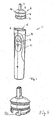
- FIG. 1 shown hand part 1 of an electric toothbrush comprises an about stabg. tubular housing 2, in which a known drive unit with an electric motor, a control unit is arranged with at least one on / off switch and a power supply in the form of a battery or a battery.
- the housing 2 is injection molded according to an advantageous embodiment of the invention in a two-component injection molding of hard plastic and soft plastic.
- the section of the housing 2 serving as a grip region 3 can be coated with a soft plastic coating.
- an operating portion 4 may be injection molded solely from soft plastic, so that in this area the housing 2 can be pressed to operate the arranged below the on / off switch can.
- the housing 2 while only a single housing opening 5, namely at its the toothbrush head facing the front end facing, while the opposite back of the housing 2, so to speak, the bottom of the housing 2, may be closed.
- the drive unit, the associated control unit and the batteries or rechargeable batteries can be used via the housing opening 5 on the brush head end face of the housing 2 in the latter.
- the housing opening 5 can be closed by a cover 6 which can be placed axially on the housing opening 5.
- this cover has 6 a projection which forms a coupling piece 7 for coupling the brush tube of a brush attachment.
- the coupling piece 7 is formed in the illustrated embodiment as a plug-in coupling piece, so that the brush attachment must only be plugged.
- a Fugangsaus supraung not shown is provided, through which the drive train, in particular its drive shaft, can be performed by the recorded in the housing 2 drive unit to the brush head.
- the lid 6 has a substantially - roughly speaking - cylindrical collar 8, which is precisely inserted into the housing opening 5 of the housing 2 can be inserted.
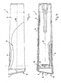
- FIG. 4 shows the collar 8 relative to the plate-shaped or slightly lenticular curved closure portion 9 in the periphery slightly set back, ie the lid 6 has a relation to the collar 8 slightly protruding edge web 10, with the cover 6 fit on the housing opening 5 surrounding housing edge 11 is seated when the lid 6 is fully inserted with its collar 8 in the housing opening 5.
- the cover 6 can in this case be latched to the housing 2.
- approximately web-shaped locking projections 12 are provided, wherein in the illustrated embodiment, two diametrically opposed locking projections 12 are provided (see. FIG. 5 ).
- the collar 8 has two opposite edge recesses 13, so that a spring-back of the latching projections 12 supporting collar sections is supported radially inwardly.
- said locking projections 12 cooperate provided on the inner wall 14 of the housing 2 locking recesses 15 which are incorporated in a wall section formed from hard plastic of the housing 2.
- said recesses 15 go completely through the hard plastic shell of the housing 2, so that they are closed only by the outer soft plastic shell of the housing 2 to the outside. With the knowledge of the position of the latching recesses 15, this makes it possible to press in the snap-in latching projections 12 from the outside.
- the locking projections 12 and the recesses 15 each have a slightly wedge-shaped contour.
- the lock-causing locking edges 16 and 17, which are formed by the housing opening 5 and the top cover facing upper sides or upper edges of the locking projections 12 and locking recesses 15, have a relation to the housing longitudinal axis 18 slightly rising course, ie they do not extend in the right Angle to the housing longitudinal axis 18.
- said locking edges 16 and 17 in an angular range of about 65 ° to 85 °, more precisely about 75 ° to 85 °, in particular about 80 °, inclined.
- the lower edge, ie the side facing away from the housing opening 5 edge of the recesses 15 and the locking projections 12 are not inclined, but run approximately rechtwlnklig to the housing longitudinal axis 18, so that the locking projections 12 and the recesses 15 receive an approximately wedge-shaped.
- the locking edges 16 of the locking projections 12 do not project at right angles from the collar 8, but are at an angle in the range of about 5 ° to 15 ° slightly upwardly rising formed (see. FIG. 5 ), so that the latching projections 12 tighten under tension in the recesses 15. An unintentional popping up with strong brushing teeth is thereby avoided.
- the latching recesses 15 and the latching projections 12 are spaced from the housing edge 11 and the edge web 10 of the cover 6 resting thereon such that when the cover 6 is engaged, it is pulled onto the housing edge 11 with a slight interference fit, in order to seal the housing 2 tightly to reach.
- the housing edge 11 made of soft plastic, so that a sealing effect can be achieved immediacy by the seat of the edge web 10 on the edge of the housing 11.
- a separate sealing ring is not essential.
- the housing edge 11 and the seated thereon lid edge is not in a direction perpendicular to the housing longitudinal axis 18 level. Rather, the housing edge 11 and the seated thereon edge web 10 of the lid 6 is chamfered, ie they extend in an acute axis to the housing 18 at an angle of less than 90 ° inclined plane.
- the angle of inclination may basically be chosen differently, but will advantageously move in a range of 70 ° to 85 °. In the illustrated embodiment, the angle is about 79 °.
- the inclined edge of the housing 11 and the corresponding inclined edge of the cover or edge web 10 of the cover 6 together form a trench slope 19, by the manner of a screw by turning the lid 6 relative to the housing 2 about the longitudinal axis 18, the latching between the lid and housing can be levered. This release of the latching is facilitated by the previously described inclination of the locking edges 16.
- the charging part for the electric toothbrush can be used as a turning tool.
- the coupling piece 7 on the cover 6 advantageously has a deviating from the circular outer contour, which is adapted to transmit a torque. Accordingly, in the housing of the charging part, a complementary recess, in particular a blind hole, be introduced, the inner contour deviates in a corresponding manner from the circular shape and is suitable to transmit a torque. Accordingly, the handpiece 1 needs to be plugged with the coupling piece 7 on the lid 6 only in this recess in the loading part, so that the lid 6 is rotatably locked on the charging member. In order to release the cover from the housing, only the charging part needs to be held and the housing 2 must be twisted or vice versa.
- the lid 6 In order to lock the lid 6 with the housing 2, it only needs to be placed on the housing 2 axially without twisting in the correct orientation and pushed into it until the latching projections 12 snap into the latching recesses 15 on the collar 8 of the lid 6.
- the first radially projecting locking projections 12 on its underside have import bevels 20 (see. FIG. 5 ), over which the collar 8 can be forced with the locking projections 12 better in the housing 2.
- a slight elastic deformation of the collar 8 radially inwardly and / or the housing 2 will arise radially outward until the latching projections 12 engage in the recesses 15.
- FIG. 6 in perspective shown cover has additional locking means 30 which can engage in zusphinliche complementary locking means on the housing.
- This additional latching can absorb forces in the longitudinal direction of the housing.
- These locking means are designed so that the lid can be solved by turning in a first direction easier than in the opposite direction.
Landscapes
- Health & Medical Sciences (AREA)
- Dentistry (AREA)
- Epidemiology (AREA)
- Life Sciences & Earth Sciences (AREA)
- Animal Behavior & Ethology (AREA)
- General Health & Medical Sciences (AREA)
- Public Health (AREA)
- Veterinary Medicine (AREA)
- Brushes (AREA)
Applications Claiming Priority (2)
| Application Number | Priority Date | Filing Date | Title |
|---|---|---|---|
| DE102005040136A DE102005040136A1 (de) | 2005-08-25 | 2005-08-25 | Handteil einer elektrischen Zahnbürste sowie Ladeteil hierfür |
| PCT/EP2006/008230 WO2007022949A2 (de) | 2005-08-25 | 2006-08-22 | Handteil einer elektrischen zahnbürste sowie ladeteil hierfür |
Publications (2)
| Publication Number | Publication Date |
|---|---|
| EP1959859A2 EP1959859A2 (de) | 2008-08-27 |
| EP1959859B1 true EP1959859B1 (de) | 2014-02-26 |
Family
ID=37433719
Family Applications (1)
| Application Number | Title | Priority Date | Filing Date |
|---|---|---|---|
| EP06791606.4A Active EP1959859B1 (de) | 2005-08-25 | 2006-08-22 | Handteil einer elektrischen zahnbürste |
Country Status (10)
| Country | Link |
|---|---|
| US (1) | US7917982B2 (es) |
| EP (1) | EP1959859B1 (es) |
| JP (1) | JP5073661B2 (es) |
| CN (1) | CN101247770B (es) |
| CA (1) | CA2619718C (es) |
| DE (1) | DE102005040136A1 (es) |
| ES (1) | ES2459619T3 (es) |
| HK (1) | HK1118694A1 (es) |
| MX (1) | MX2008002143A (es) |
| WO (1) | WO2007022949A2 (es) |
Families Citing this family (9)
| Publication number | Priority date | Publication date | Assignee | Title |
|---|---|---|---|---|
| DE202009003421U1 (de) | 2009-03-10 | 2009-05-20 | Molitor, Wilfried Ernst | Elektrische Zahnbürste |
| EP2621050B1 (en) * | 2012-01-27 | 2015-04-08 | Braun GmbH | Inductive Charger for Hand-Held Appliances |
| USD773192S1 (en) | 2015-01-09 | 2016-12-06 | Ranir, Llc | Powered toothbrush handle |
| US10226315B2 (en) | 2015-06-30 | 2019-03-12 | Braun Gmbh | Multi-component plastic housing |
| US10583625B2 (en) | 2015-06-30 | 2020-03-10 | Braun Gmbh | Plurality of mass-produced multi-component plastic housings |
| DE102016218273B3 (de) * | 2016-09-22 | 2018-01-04 | Sirona Dental Systems Gmbh | Handstückkopf für ein zahnärztliches Handstück |
| USD858997S1 (en) | 2017-11-17 | 2019-09-10 | Colgate-Palmolive Company | Tracking module for an oral care implement |
| USD893881S1 (en) | 2017-11-17 | 2020-08-25 | Colgate-Palmolive Company | Oral care apparatus |
| USD858105S1 (en) | 2017-11-17 | 2019-09-03 | Colgate-Palmolive Company | Oral care implement |
Family Cites Families (21)
| Publication number | Priority date | Publication date | Assignee | Title |
|---|---|---|---|---|
| US3379906A (en) * | 1965-08-27 | 1968-04-23 | Sunbeam Corp | Electric appliance with selective motion conversion means |
| US3577579A (en) * | 1969-10-29 | 1971-05-04 | John P Duve | Electric toothbrush |
| GB1387262A (en) * | 1971-05-20 | 1975-03-12 | Beecham Group Ltd | Bottle closure |
| US4991249A (en) * | 1989-02-09 | 1991-02-12 | Suroff Leonard W | Ultrasonic toothbrush |
| DE4201091C1 (es) | 1992-01-17 | 1993-02-11 | Braun Ag, 6000 Frankfurt, De | |
| NL9202261A (nl) * | 1992-12-24 | 1994-07-18 | Kornelis Kunsthars Prod Ind Bv | Houder met deksel. |
| JP2668631B2 (ja) * | 1993-03-19 | 1997-10-27 | 英二 岡田 | 所定振動数を有する電動歯ブラシの歯磨き方法 |
| JPH07220704A (ja) * | 1994-01-28 | 1995-08-18 | Seikosha Co Ltd | 筒形電気機器の電池電源装置 |
| GB2313367A (en) * | 1996-05-24 | 1997-11-26 | Beeson & Sons Ltd | Container closure assemblies with bidirectional opening |
| JPH11318952A (ja) * | 1998-05-18 | 1999-11-24 | Omron Corp | 電動歯ブラシ |
| DE19940369C2 (de) * | 1999-08-25 | 2002-05-29 | Perfect Steam Appliance Ltd | Elektrisch antreibbare Zahnbürste |
| DE10061327A1 (de) * | 2000-12-08 | 2002-06-20 | Braun Gmbh | Zahnbürstengehäuse |
| US6889829B2 (en) * | 2001-06-29 | 2005-05-10 | Homedics, Inc. | Automatic electric toothbrush in a display package |
| JP2003189936A (ja) * | 2001-12-25 | 2003-07-08 | Matsushita Electric Works Ltd | 電動歯ブラシのハウジング |
| JP3586252B2 (ja) * | 2002-02-27 | 2004-11-10 | 朝日医理科株式会社 | 超音波歯ブラシ |
| US7122921B2 (en) | 2002-05-02 | 2006-10-17 | Koninklijke Philips Electronics N.V. | Top loading internal assembly for a power toothbrush |
| CN2569766Y (zh) * | 2002-08-13 | 2003-09-03 | 林云声 | 电动牙刷的扣榫装置 |
| US7228583B2 (en) * | 2002-09-13 | 2007-06-12 | Church & Dwight Co., Inc. | Electric toothbrush housing design |
| WO2004054467A1 (en) | 2002-12-18 | 2004-07-01 | Koninklijke Philips Electronics N.V. | System for removably joining a driven member to a driven member with workpiece |
| WO2005000149A1 (en) | 2003-06-27 | 2005-01-06 | Koninklijke Philips Electronics, N.V. | Brushhead attachment system for a power toothbrush |
| DE10353715A1 (de) * | 2003-11-17 | 2005-06-23 | Hübl, Friedrich | Verschlußanordnung für Behälter |
-
2005
- 2005-08-25 DE DE102005040136A patent/DE102005040136A1/de not_active Withdrawn
-
2006
- 2006-08-22 CN CN2006800309930A patent/CN101247770B/zh active Active
- 2006-08-22 WO PCT/EP2006/008230 patent/WO2007022949A2/de active Application Filing
- 2006-08-22 EP EP06791606.4A patent/EP1959859B1/de active Active
- 2006-08-22 JP JP2008527381A patent/JP5073661B2/ja active Active
- 2006-08-22 MX MX2008002143A patent/MX2008002143A/es active IP Right Grant
- 2006-08-22 CA CA2619718A patent/CA2619718C/en active Active
- 2006-08-22 ES ES06791606.4T patent/ES2459619T3/es active Active
- 2006-08-22 US US12/064,588 patent/US7917982B2/en active Active
-
2008
- 2008-09-30 HK HK08110919.9A patent/HK1118694A1/xx not_active IP Right Cessation
Also Published As
| Publication number | Publication date |
|---|---|
| WO2007022949A3 (de) | 2007-05-31 |
| HK1118694A1 (en) | 2009-02-20 |
| US7917982B2 (en) | 2011-04-05 |
| CA2619718C (en) | 2013-07-30 |
| WO2007022949A2 (de) | 2007-03-01 |
| MX2008002143A (es) | 2008-04-22 |
| ES2459619T3 (es) | 2014-05-12 |
| JP5073661B2 (ja) | 2012-11-14 |
| CN101247770A (zh) | 2008-08-20 |
| DE102005040136A1 (de) | 2007-03-01 |
| CN101247770B (zh) | 2010-09-08 |
| US20080216258A1 (en) | 2008-09-11 |
| CA2619718A1 (en) | 2007-03-01 |
| EP1959859A2 (de) | 2008-08-27 |
| JP2009505704A (ja) | 2009-02-12 |
Similar Documents
| Publication | Publication Date | Title |
|---|---|---|
| EP1959859B1 (de) | Handteil einer elektrischen zahnbürste | |
| DE19828059C2 (de) | Anschlußarmatur mit einem durch Schlitze in Haltezungen aufgeteilten Befestigungsvorsprung | |
| EP3008352B1 (de) | Steckkupplung mit einem elastisch verformbaren kupplungsteil sowie einbauverfahren dafür | |
| DE1775302C3 (de) | Schlauchkupplung | |
| EP1845208B1 (de) | Installationseinrichtung für Sanitärelemente | |
| DE2328412B2 (de) | Befestigungseleme nt | |
| WO2009152996A1 (de) | Elektrische zahnbürste | |
| EP0232831A2 (de) | Kabelverschraubung | |
| WO2012025418A1 (de) | Stecker, insbesondere photovoltaikstecker | |
| EP2303180A1 (de) | Vorrichtung zum anbringen einer abformkappe an einem zahnimplantat | |
| WO2014060608A2 (de) | Lösbare verbindungsvorrichtung für die werkzeuglose montage | |
| WO2008074410A1 (de) | Zahnbürste sowie aufsatzteil hierfür | |
| EP1500829A1 (de) | Schraubverbindungsanordnung zum Verbinden zweier Bauteile | |
| EP1840441A2 (de) | Schlauchanschlusselement | |
| DE4231320A1 (de) | Vorrichtung zum lösbaren Verbinden von mindestens zwei Gegenständen | |
| EP4162188A1 (de) | Vorrichtung zum verbinden zweier röhrenförmiger objekte | |
| EP0357607A1 (de) | Vorrichtung zur zugentlastung von kabeln | |
| EP3517009B1 (de) | Wc-deckelgarnitur mit mindestens einem befestigungselement und wc mit verriegelungseinrichtung | |
| DE102007003752A1 (de) | Kabeleinführung mit Zugentlastung | |
| DE202004021537U1 (de) | Multifunktionales Funktionsteil für einen Schraubendreher | |
| DE3730033C2 (es) | ||
| CA1247407A (en) | Shear-resistant fastener | |
| DE102006041998B4 (de) | Kupplungsvorrichtung | |
| DE102010034630A1 (de) | Elektrische Steckverbindung | |
| EP0809339B1 (de) | Elektrisches Installationsgerät |
Legal Events
| Date | Code | Title | Description |
|---|---|---|---|
| PUAI | Public reference made under article 153(3) epc to a published international application that has entered the european phase |
Free format text: ORIGINAL CODE: 0009012 |
|
| 17P | Request for examination filed |
Effective date: 20071220 |
|
| AK | Designated contracting states |
Kind code of ref document: A2 Designated state(s): AT BE BG CH CY CZ DE DK EE ES FI FR GB GR HU IE IS IT LI LT LU LV MC NL PL PT RO SE SI SK TR |
|
| DAX | Request for extension of the european patent (deleted) | ||
| 17Q | First examination report despatched |
Effective date: 20120917 |
|
| GRAP | Despatch of communication of intention to grant a patent |
Free format text: ORIGINAL CODE: EPIDOSNIGR1 |
|
| INTG | Intention to grant announced |
Effective date: 20130924 |
|
| GRAS | Grant fee paid |
Free format text: ORIGINAL CODE: EPIDOSNIGR3 |
|
| GRAA | (expected) grant |
Free format text: ORIGINAL CODE: 0009210 |
|
| AK | Designated contracting states |
Kind code of ref document: B1 Designated state(s): AT BE BG CH CY CZ DE DK EE ES FI FR GB GR HU IE IS IT LI LT LU LV MC NL PL PT RO SE SI SK TR |
|
| REG | Reference to a national code |
Ref country code: GB Ref legal event code: FG4D Free format text: NOT ENGLISH |
|
| REG | Reference to a national code |
Ref country code: CH Ref legal event code: NV Representative=s name: BOHEST AG, CH Ref country code: CH Ref legal event code: EP |
|
| REG | Reference to a national code |
Ref country code: SE Ref legal event code: TRGR |
|
| REG | Reference to a national code |
Ref country code: AT Ref legal event code: REF Ref document number: 653101 Country of ref document: AT Kind code of ref document: T Effective date: 20140315 |
|
| REG | Reference to a national code |
Ref country code: NL Ref legal event code: T3 |
|
| REG | Reference to a national code |
Ref country code: IE Ref legal event code: FG4D Free format text: LANGUAGE OF EP DOCUMENT: GERMAN |
|
| REG | Reference to a national code |
Ref country code: DE Ref legal event code: R096 Ref document number: 502006013550 Country of ref document: DE Effective date: 20140410 |
|
| REG | Reference to a national code |
Ref country code: ES Ref legal event code: FG2A Ref document number: 2459619 Country of ref document: ES Kind code of ref document: T3 Effective date: 20140512 |
|
| REG | Reference to a national code |
Ref country code: LT Ref legal event code: MG4D |
|
| PG25 | Lapsed in a contracting state [announced via postgrant information from national office to epo] |
Ref country code: LT Free format text: LAPSE BECAUSE OF FAILURE TO SUBMIT A TRANSLATION OF THE DESCRIPTION OR TO PAY THE FEE WITHIN THE PRESCRIBED TIME-LIMIT Effective date: 20140226 Ref country code: IS Free format text: LAPSE BECAUSE OF FAILURE TO SUBMIT A TRANSLATION OF THE DESCRIPTION OR TO PAY THE FEE WITHIN THE PRESCRIBED TIME-LIMIT Effective date: 20140626 |
|
| PG25 | Lapsed in a contracting state [announced via postgrant information from national office to epo] |
Ref country code: CY Free format text: LAPSE BECAUSE OF FAILURE TO SUBMIT A TRANSLATION OF THE DESCRIPTION OR TO PAY THE FEE WITHIN THE PRESCRIBED TIME-LIMIT Effective date: 20140226 Ref country code: PT Free format text: LAPSE BECAUSE OF FAILURE TO SUBMIT A TRANSLATION OF THE DESCRIPTION OR TO PAY THE FEE WITHIN THE PRESCRIBED TIME-LIMIT Effective date: 20140626 Ref country code: FI Free format text: LAPSE BECAUSE OF FAILURE TO SUBMIT A TRANSLATION OF THE DESCRIPTION OR TO PAY THE FEE WITHIN THE PRESCRIBED TIME-LIMIT Effective date: 20140226 |
|
| PG25 | Lapsed in a contracting state [announced via postgrant information from national office to epo] |
Ref country code: LV Free format text: LAPSE BECAUSE OF FAILURE TO SUBMIT A TRANSLATION OF THE DESCRIPTION OR TO PAY THE FEE WITHIN THE PRESCRIBED TIME-LIMIT Effective date: 20140226 |
|
| PG25 | Lapsed in a contracting state [announced via postgrant information from national office to epo] |
Ref country code: RO Free format text: LAPSE BECAUSE OF FAILURE TO SUBMIT A TRANSLATION OF THE DESCRIPTION OR TO PAY THE FEE WITHIN THE PRESCRIBED TIME-LIMIT Effective date: 20140226 Ref country code: EE Free format text: LAPSE BECAUSE OF FAILURE TO SUBMIT A TRANSLATION OF THE DESCRIPTION OR TO PAY THE FEE WITHIN THE PRESCRIBED TIME-LIMIT Effective date: 20140226 Ref country code: CZ Free format text: LAPSE BECAUSE OF FAILURE TO SUBMIT A TRANSLATION OF THE DESCRIPTION OR TO PAY THE FEE WITHIN THE PRESCRIBED TIME-LIMIT Effective date: 20140226 Ref country code: DK Free format text: LAPSE BECAUSE OF FAILURE TO SUBMIT A TRANSLATION OF THE DESCRIPTION OR TO PAY THE FEE WITHIN THE PRESCRIBED TIME-LIMIT Effective date: 20140226 |
|
| REG | Reference to a national code |
Ref country code: DE Ref legal event code: R097 Ref document number: 502006013550 Country of ref document: DE |
|
| PG25 | Lapsed in a contracting state [announced via postgrant information from national office to epo] |
Ref country code: SK Free format text: LAPSE BECAUSE OF FAILURE TO SUBMIT A TRANSLATION OF THE DESCRIPTION OR TO PAY THE FEE WITHIN THE PRESCRIBED TIME-LIMIT Effective date: 20140226 Ref country code: PL Free format text: LAPSE BECAUSE OF FAILURE TO SUBMIT A TRANSLATION OF THE DESCRIPTION OR TO PAY THE FEE WITHIN THE PRESCRIBED TIME-LIMIT Effective date: 20140226 |
|
| PLBE | No opposition filed within time limit |
Free format text: ORIGINAL CODE: 0009261 |
|
| STAA | Information on the status of an ep patent application or granted ep patent |
Free format text: STATUS: NO OPPOSITION FILED WITHIN TIME LIMIT |
|
| 26N | No opposition filed |
Effective date: 20141127 |
|
| REG | Reference to a national code |
Ref country code: DE Ref legal event code: R097 Ref document number: 502006013550 Country of ref document: DE Effective date: 20141127 |
|
| PG25 | Lapsed in a contracting state [announced via postgrant information from national office to epo] |
Ref country code: MC Free format text: LAPSE BECAUSE OF FAILURE TO SUBMIT A TRANSLATION OF THE DESCRIPTION OR TO PAY THE FEE WITHIN THE PRESCRIBED TIME-LIMIT Effective date: 20140226 Ref country code: LU Free format text: LAPSE BECAUSE OF FAILURE TO SUBMIT A TRANSLATION OF THE DESCRIPTION OR TO PAY THE FEE WITHIN THE PRESCRIBED TIME-LIMIT Effective date: 20140822 Ref country code: IT Free format text: LAPSE BECAUSE OF FAILURE TO SUBMIT A TRANSLATION OF THE DESCRIPTION OR TO PAY THE FEE WITHIN THE PRESCRIBED TIME-LIMIT Effective date: 20140226 |
|
| PG25 | Lapsed in a contracting state [announced via postgrant information from national office to epo] |
Ref country code: BE Free format text: LAPSE BECAUSE OF NON-PAYMENT OF DUE FEES Effective date: 20140831 |
|
| REG | Reference to a national code |
Ref country code: IE Ref legal event code: MM4A |
|
| PG25 | Lapsed in a contracting state [announced via postgrant information from national office to epo] |
Ref country code: SI Free format text: LAPSE BECAUSE OF FAILURE TO SUBMIT A TRANSLATION OF THE DESCRIPTION OR TO PAY THE FEE WITHIN THE PRESCRIBED TIME-LIMIT Effective date: 20140226 |
|
| PG25 | Lapsed in a contracting state [announced via postgrant information from national office to epo] |
Ref country code: IE Free format text: LAPSE BECAUSE OF NON-PAYMENT OF DUE FEES Effective date: 20140822 |
|
| REG | Reference to a national code |
Ref country code: AT Ref legal event code: MM01 Ref document number: 653101 Country of ref document: AT Kind code of ref document: T Effective date: 20140822 |
|
| PG25 | Lapsed in a contracting state [announced via postgrant information from national office to epo] |
Ref country code: AT Free format text: LAPSE BECAUSE OF NON-PAYMENT OF DUE FEES Effective date: 20140822 |
|
| PG25 | Lapsed in a contracting state [announced via postgrant information from national office to epo] |
Ref country code: BG Free format text: LAPSE BECAUSE OF FAILURE TO SUBMIT A TRANSLATION OF THE DESCRIPTION OR TO PAY THE FEE WITHIN THE PRESCRIBED TIME-LIMIT Effective date: 20140226 |
|
| PG25 | Lapsed in a contracting state [announced via postgrant information from national office to epo] |
Ref country code: GR Free format text: LAPSE BECAUSE OF FAILURE TO SUBMIT A TRANSLATION OF THE DESCRIPTION OR TO PAY THE FEE WITHIN THE PRESCRIBED TIME-LIMIT Effective date: 20140527 |
|
| REG | Reference to a national code |
Ref country code: FR Ref legal event code: PLFP Year of fee payment: 11 |
|
| PG25 | Lapsed in a contracting state [announced via postgrant information from national office to epo] |
Ref country code: TR Free format text: LAPSE BECAUSE OF FAILURE TO SUBMIT A TRANSLATION OF THE DESCRIPTION OR TO PAY THE FEE WITHIN THE PRESCRIBED TIME-LIMIT Effective date: 20140226 Ref country code: HU Free format text: LAPSE BECAUSE OF FAILURE TO SUBMIT A TRANSLATION OF THE DESCRIPTION OR TO PAY THE FEE WITHIN THE PRESCRIBED TIME-LIMIT; INVALID AB INITIO Effective date: 20060822 |
|
| REG | Reference to a national code |
Ref country code: FR Ref legal event code: PLFP Year of fee payment: 12 |
|
| REG | Reference to a national code |
Ref country code: FR Ref legal event code: PLFP Year of fee payment: 13 |
|
| P01 | Opt-out of the competence of the unified patent court (upc) registered |
Effective date: 20230430 |
|
| PGFP | Annual fee paid to national office [announced via postgrant information from national office to epo] |
Ref country code: NL Payment date: 20230719 Year of fee payment: 18 |
|
| PGFP | Annual fee paid to national office [announced via postgrant information from national office to epo] |
Ref country code: GB Payment date: 20230629 Year of fee payment: 18 Ref country code: ES Payment date: 20230908 Year of fee payment: 18 Ref country code: CH Payment date: 20230902 Year of fee payment: 18 |
|
| PGFP | Annual fee paid to national office [announced via postgrant information from national office to epo] |
Ref country code: SE Payment date: 20230630 Year of fee payment: 18 Ref country code: FR Payment date: 20230703 Year of fee payment: 18 Ref country code: DE Payment date: 20230703 Year of fee payment: 18 |