EP1500829A1 - Schraubverbindungsanordnung zum Verbinden zweier Bauteile - Google Patents
Schraubverbindungsanordnung zum Verbinden zweier Bauteile Download PDFInfo
- Publication number
- EP1500829A1 EP1500829A1 EP04009585A EP04009585A EP1500829A1 EP 1500829 A1 EP1500829 A1 EP 1500829A1 EP 04009585 A EP04009585 A EP 04009585A EP 04009585 A EP04009585 A EP 04009585A EP 1500829 A1 EP1500829 A1 EP 1500829A1
- Authority
- EP
- European Patent Office
- Prior art keywords
- screw
- arrangement according
- blind rivet
- connection arrangement
- screw connection
- Prior art date
- Legal status (The legal status is an assumption and is not a legal conclusion. Google has not performed a legal analysis and makes no representation as to the accuracy of the status listed.)
- Granted
Links
Images

Classifications
-
- F—MECHANICAL ENGINEERING; LIGHTING; HEATING; WEAPONS; BLASTING
- F16—ENGINEERING ELEMENTS AND UNITS; GENERAL MEASURES FOR PRODUCING AND MAINTAINING EFFECTIVE FUNCTIONING OF MACHINES OR INSTALLATIONS; THERMAL INSULATION IN GENERAL
- F16B—DEVICES FOR FASTENING OR SECURING CONSTRUCTIONAL ELEMENTS OR MACHINE PARTS TOGETHER, e.g. NAILS, BOLTS, CIRCLIPS, CLAMPS, CLIPS OR WEDGES; JOINTS OR JOINTING
- F16B5/00—Joining sheets or plates, e.g. panels, to one another or to strips or bars parallel to them
- F16B5/02—Joining sheets or plates, e.g. panels, to one another or to strips or bars parallel to them by means of fastening members using screw-thread
- F16B5/0258—Joining sheets or plates, e.g. panels, to one another or to strips or bars parallel to them by means of fastening members using screw-thread using resiliently deformable sleeves, grommets or inserts
-
- F—MECHANICAL ENGINEERING; LIGHTING; HEATING; WEAPONS; BLASTING
- F16—ENGINEERING ELEMENTS AND UNITS; GENERAL MEASURES FOR PRODUCING AND MAINTAINING EFFECTIVE FUNCTIONING OF MACHINES OR INSTALLATIONS; THERMAL INSULATION IN GENERAL
- F16B—DEVICES FOR FASTENING OR SECURING CONSTRUCTIONAL ELEMENTS OR MACHINE PARTS TOGETHER, e.g. NAILS, BOLTS, CIRCLIPS, CLAMPS, CLIPS OR WEDGES; JOINTS OR JOINTING
- F16B13/00—Dowels or other devices fastened in walls or the like by inserting them in holes made therein for that purpose
- F16B13/02—Dowels or other devices fastened in walls or the like by inserting them in holes made therein for that purpose in one piece with protrusions or ridges on the shaft
-
- F—MECHANICAL ENGINEERING; LIGHTING; HEATING; WEAPONS; BLASTING
- F16—ENGINEERING ELEMENTS AND UNITS; GENERAL MEASURES FOR PRODUCING AND MAINTAINING EFFECTIVE FUNCTIONING OF MACHINES OR INSTALLATIONS; THERMAL INSULATION IN GENERAL
- F16B—DEVICES FOR FASTENING OR SECURING CONSTRUCTIONAL ELEMENTS OR MACHINE PARTS TOGETHER, e.g. NAILS, BOLTS, CIRCLIPS, CLAMPS, CLIPS OR WEDGES; JOINTS OR JOINTING
- F16B13/00—Dowels or other devices fastened in walls or the like by inserting them in holes made therein for that purpose
- F16B13/12—Separate metal or non-separate or non-metal dowel sleeves fastened by inserting the screw, nail or the like
- F16B13/124—Separate metal or non-separate or non-metal dowel sleeves fastened by inserting the screw, nail or the like fastened by inserting a threaded element, e.g. screw or bolt
-
- F—MECHANICAL ENGINEERING; LIGHTING; HEATING; WEAPONS; BLASTING
- F16—ENGINEERING ELEMENTS AND UNITS; GENERAL MEASURES FOR PRODUCING AND MAINTAINING EFFECTIVE FUNCTIONING OF MACHINES OR INSTALLATIONS; THERMAL INSULATION IN GENERAL
- F16B—DEVICES FOR FASTENING OR SECURING CONSTRUCTIONAL ELEMENTS OR MACHINE PARTS TOGETHER, e.g. NAILS, BOLTS, CIRCLIPS, CLAMPS, CLIPS OR WEDGES; JOINTS OR JOINTING
- F16B19/00—Bolts without screw-thread; Pins, including deformable elements; Rivets
- F16B19/04—Rivets; Spigots or the like fastened by riveting
- F16B19/08—Hollow rivets; Multi-part rivets
- F16B19/10—Hollow rivets; Multi-part rivets fastened by expanding mechanically
- F16B19/1027—Multi-part rivets
- F16B19/1036—Blind rivets
- F16B19/1081—Blind rivets fastened by a drive-pin
Definitions
- the present invention relates to a screw connection arrangement for Connecting two components consisting of a screw and a nut-like blind rivet exists, which can be inserted in mounting holes of the two components and for Making the connection can be screwed together.
- Such screw connection arrangements are known. Will to Connect the two components of the screw in the from an elastically deformable Material screwed in existing nut-like blind rivet, so widening elastically deformable portion of the blind rivet to a Nietwulst on which applies the associated component and thus establishes the connection in the axial direction.
- the rivet bead which in principle has the shape of a ring flange, too soft, so the components are not held together with sufficient holding power.
- the rivet bead is too hard, so there is a danger that it will become brittle, what the Life of the compound reduced accordingly.
- screw connections are limited load capacity.
- the present invention is based on the object, a fferfactsan extract for connecting two components of a screw and a mother-like blind rivet to create, with ease of manufacture and comparatively small dimensions, a functionally reliable, heavy duty and permanent connection of the two components ensures.
- the blind rivet has a cylindrical body, the its outside with a multi-speed, preferably four-speed, helix is provided, wherein the number of helical turns equal to the number of corners of the polygonal mounting hole is. Furthermore, the dimensions of the helix and the dimensions of the polygonal mounting hole are coordinated so that in the assembled state, the helical turns the corners of the polygonal mounting hole largely complete. This creates a rotation between the blind rivet and the associated component.
- the "rivet" of the blind rivet is formed by the helix. Because the folding zone is radially outward compared to the prior art, can be in the According to the invention trained ertellsanowski the same strength as in the prior art with smaller dimensions of the screw and the Achieve blind rivets including the mounting holes. Otherwise, according to the invention trained blind rivet has no undercut, simplifies its Production.
- the blind rivet made of plastic can be a simple Plate tool can be used. For removing the blind rivet from the plate tool is sufficient a linear ejector, in which the helix self-rotating from the plate tool demolded.
- the helix has the shape of a pointed thread and a Pitch angle greater than its self-locking angle.
- the blind rivet will Therefore, when mounting in the polygonal mounting hole of the relevant component Pressed in the axial direction, with the large spiral pitch of the Blind rivet performs a rotating movement. If the component has a sufficient thickness, so arises due to the helical course of the coil as a Captive acting clamping system between the helix and the polygonal mounting hole. At relatively low wall thickness of the relevant Component, it is recommended to the outside of the main body of the blind rivet To provide nubs as a further captive.
- the main body of the blind rivet provided at its one end with a flange having on one side a sealing lip has, in the manufacture of the screw in sealing system with the associated component is pressed. Is the main body of the blind rivet on his the other end closed by a bottom, it creates a waterproof Screw connection.
- Screw connection arrangement is used for connecting two plate-shaped components 2, 4, which only from one side, in the drawing only from the top forth, are accessible.
- the component 2 is the body panel and at the component 4 to the wheel housing shell for a motor vehicle. It however, it should be understood that the invention is not limited thereto.
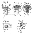
- the screw connection arrangement consists of a screw 6, which in FIG 1 is shown as a single part, and a mother-like blind rivet 8, in the Figures 2 to 6 is shown as a single part.
- the screw 6 is made in the usual way a shaft with a thread 10 and a screw head 12, which with a Key receptacle 14 is provided for rotating the screw.
- the screw 6 is in illustrated embodiment as a self-tapping screw with neuroscience resumeem Formed round thread, which preferably consists of a high-strength plastic, although a screw made of steel could be used.
- nut-like blind rivet 8 has a sleeve-shaped base body 16, at its one axial end with a Flange 18 is provided.
- the flange 18 has on its underside a sealing lip 19, their function will be explained below.
- the main body 16 has a receiving bore 20 for receiving the Screw 6.
- the receiving bore 20 consists of a lower bore portion 22 smaller diameter and an upper bore portion 24 larger Diameter, which are connected by a chamfer.
- the diameter of the bore portion 22 is in this case dimensioned so that the self-tapping Screw 6 when screwing into the blind rivet 8 in this area a thread shaped.
- the blind rivet 8 could be in the area of the bore section 22 also with a preformed thread for receiving the thread 10 of Be provided screw 6.
- the diameter of the bore portion 24 corresponds to the outer diameter the thread 10 of the screw 6, so that the screw 6 unhindered in the Hole section 24 can be introduced. Due to the larger diameter of the bore portion 24 is the wall thickness of the blind rivet 8 in this area reduced, wherein the wall thickness is chosen so that the blind rivet 8 in this Area can be relatively easily deformed, as will be explained in more detail.
- the main body 16 is at its side remote from the flange 18 axial End of a bottom 26 closed, leaving the interior of the receiving bore 20 is watertight at this end. If the screw connection is not waterproof must be, the relevant end of the body 16 can also remain open, such as this in the modified embodiment of the blind rivet 8 'in Figure 7 of the case is.
Landscapes
- Engineering & Computer Science (AREA)
- General Engineering & Computer Science (AREA)
- Mechanical Engineering (AREA)
- Connection Of Plates (AREA)
- Dowels (AREA)
Abstract
Description
Claims (22)
- Verbindungsanordnung zum Verbinden zweier Bauteile (2, 4), mit
einer Schraube (6) und einem mutterartigen Blindniet (8), die in Befestigungslöcher (36, 40) der beiden Bauteile (2, 4) einsteckbar und zum Herstellen der Verbindung miteinander verschraubbar sind, wobei das Befestigungsloch (36) eines der Bauteile (2, 4) als Mehreck ausgebildet ist,
welcher Blindniet (8) aus einem elastisch verformbaren Material besteht und einen Grundkörper (16) aufweist, der mit einer Aufnahmebohrung (20) für das Gewinde (10) der Schraube (6) und an seiner Außenseite (28) mit einer mehrgängigen Wendel (30) versehen ist, deren Außendurchmesser dem Abstand jeweils zweier diagonal gegenüberliegender Ecken des mehreckigen Befestigungsloches (36) entspricht und deren Gängeanzahl gleich der Anzahl der Ecken des mehreckigen Befestigungsloches (36) ist,
so dass beim Einschrauben der Schraube (6) in die Aufnahmebohrung (20) des Blindniets (8) der Grundkörper (16) und die Wendel (30) gefaltet und dadurch die Gänge (32) der Wendel (30) mit einem Teil ihrer Flanken an das zugehörige Bauteil (2) angedrückt werden. - Schraubverbindung nach Anspruch 1, dadurch gekennzeichnet, dass die Seitenlänge des mehreckigen Befestigungsloches (36) dem Außendurchmesser des zylindrisch ausgebildeten Grundkörpers (16) entspricht.
- Schraubverbindungsanordnung nach Anspruch 1 oder 2, dadurch gekennzeichnet, dass die Aufnahmebohrung (20) des Grundkörpers (16) einen Bohrungsabschnitt (22) kleineren Durchmessers zwecks Gewindeeingriff mit der Schraube (6) und einen Bohrungsabschnitt (24) größeren Durchmessers zur Verringerung der Wandstärke des Grundkörpers (16) hat, in dessen Bereich die Faltung des Grundkörpers (16) und der Wendel (30) erfolgt.
- Schraubverbindungsanordnung nach Anspruch 3, dadurch gekennzeichnet, dass der Grundkörper (16) an seiner Innenseite im Bereich seines Bohrungsabschnittes (24) größeren Durchmessers mit mehreren wendelförmig verlaufenden Stützrippen (25) versehen ist, die beim Faltvorgang an dem Außenumfang des Gewindes (10) der Schraube (6) anliegen.
- Schraubverbindungsanordnung nach einem der vorhergehenden Ansprüche, dadurch gekennzeichnet, dass die Wendel (30) die Form eines Spitzgewindes hat.
- Schraubverbindungsanordnung nach Anspruch 5, dadurch gekennzeichnet, dass das Profil des Spitzgewindes der Wendel (30) an die Ecken des mehreckigen Befestigungsloches (36) angepasst ist.
- Schraubverbindungsanordnung nach einem der vorhergehenden Ansprüche, dadurch gekennzeichnet, dass die Wendel (30) einen Steigungswinkel hat, der größer als der Selbsthemmungswinkel der Wendel (30) ist.
- Schraubverbindungsanordnung nach einem der vorhergehenden Ansprüche, dadurch gekennzeichnet, dass die Wendel (30) viergängig und das mehreckige Befestigungsloch (36) quadratisch ist.
- Schraubverbindungsanordnung nach einem der vorhergehenden Ansprüche, dadurch gekennzeichnet, dass die Gänge (32) der Wendel (30) an ihrem einen Ende jeweils eine auslaufende Fase (34) als Findehilfe beim Einführen des Blindniets (8) in das mehreckige Befestigungsloch (36) aufweisen.
- Schraubverbindungsanordnung nach einem der vorhergehenden Ansprüche, dadurch gekennzeichnet, dass der Grundkörper (16) des Blindniets (8) an seinem einen Ende einen Flansch (18) hat, der im eingebauten Zustand zwischen den Bauteilen (2, 4) liegt und an einer Seite mit einer Dichtlippe (19) versehen ist.
- Schraubverbindungsanordnung nach Anspruch 10, dadurch gekennzeichnet, dass die Gänge (32) der Wendel (30) an ihren an dem Flansch (18) angrenzenden Ende in einen querschnittserweiterten, die Zwischenräume der Gänge (32) ausfüllenden Körperabschnitt (35) mit einer Außenfläche (37) übergehen, die im wesentlichen an die Querschnittsform des mehreckigen Befestigungsloches (36) angepasst ist.
- Schraubverbindungsanordnung nach einem der vorhergehenden Ansprüche, dadurch gekennzeichnet, dass der Grundkörper (16) des Blindniets (8) an seinem von den Bauteilen (2, 4) abgewandten Ende durch einen Boden (26) verschlossen ist.
- Schraubverbindungsanordnung nach einem der Ansprüche 1 bis 11, dadurch gekennzeichnet, dass der Grundkörper (16) des Blindniets (8) an seinem von den Bauteilen (2, 4) abgewandten Ende offen ist.
- Schraubverbindungsanordnung nach einem der vorhergehenden Ansprüche, dadurch gekennzeichnet, dass das Befestigungsloch (40) des anderen Bauteils (4) kreisrund ist und einen Durchmesser hat, der dem Außendurchmesser des Gewindes (10) der Schraube (6) entspricht.
- Schraubverbindungsanordnung nach einem der vorhergehenden Ansprüche, dadurch gekennzeichnet, dass der Grundkörper (16) des Blindniets (8) an seiner Außenseite Noppen (38) hat, die als Verliersicherung dienen.
- Schraubverbindungsanordnung nach einem der vorhergehenden Ansprüche, dadurch gekennzeichnet, dass die Schraube (6) als selbstfurchende Schraube ausgebildet ist, die beim Einschrauben in einen glatt ausgebildeten Bohrungsabschnitt (22) der Aufnahmebohrung (20) des Grundkörpers (16) des Blindniets (8) ein entsprechendes Gewinde formt.
- Schraubverbindungsanordnung nach einem der Ansprüche 1 bis 15, dadurch gekennzeichnet, dass die Aufnahmebohrung (20) des Grundkörpers (16) des Blindniets (8) ein vorgeformtes Gewinde hat.
- Schraubverbindungsanordnung nach einem der vorhergehenden Ansprüche, dadurch gekennzeichnet, dass die Schraube (6) aus Kunststoff oder Metall besteht.
- Schraubverbindungsanordnung nach einem der vorhergehenden Ansprüche, dadurch gekennzeichnet, dass der Blindniet (8) aus einem schlagzähen Polyamid oder einem anderen schlagzähen Kunststoff besteht.
- Schraubverbindungsanordnung nach einem der Ansprüche 1 bis 15, dadurch gekennzeichnet, dass der Blindniet (8) aus einem elastomeren Kunststoff oder Gummi besteht.
- Blindniet für eine Schraubverbindungsanordnung nach einem der vorhergehenden Ansprüche.
- Schraube für eine Schraubverbindungsanordnung nach einem der vorhergehenden Ansprüche.
Applications Claiming Priority (2)
| Application Number | Priority Date | Filing Date | Title |
|---|---|---|---|
| DE20311263U DE20311263U1 (de) | 2003-07-22 | 2003-07-22 | Schraubverbindungsanordnung zum Verbinden zweier Bauteile |
| DE20311263U | 2003-07-22 |
Publications (2)
| Publication Number | Publication Date |
|---|---|
| EP1500829A1 true EP1500829A1 (de) | 2005-01-26 |
| EP1500829B1 EP1500829B1 (de) | 2006-07-05 |
Family
ID=28051640
Family Applications (1)
| Application Number | Title | Priority Date | Filing Date |
|---|---|---|---|
| EP04009585A Expired - Lifetime EP1500829B1 (de) | 2003-07-22 | 2004-04-22 | Schraubverbindungsanordnung zum Verbinden zweier Bauteile |
Country Status (3)
| Country | Link |
|---|---|
| US (1) | US6926483B2 (de) |
| EP (1) | EP1500829B1 (de) |
| DE (2) | DE20311263U1 (de) |
Families Citing this family (21)
| Publication number | Priority date | Publication date | Assignee | Title |
|---|---|---|---|---|
| US20060103282A1 (en) * | 2003-03-12 | 2006-05-18 | Avendano Jose G | Fastening system for appliance cabinet assembly |
| DE10329826A1 (de) * | 2003-06-27 | 2005-01-13 | Festool Gmbh | Schleifteller |
| DE102004003240A1 (de) * | 2004-01-21 | 2005-08-11 | Newfrey Llc, Newark | Blindnietmutter |
| DE102004021484B4 (de) * | 2004-04-30 | 2018-11-29 | Böllhoff Verbindungstechnik GmbH | Verfahren zum Herstellen einer Verbindungsanordnung |
| DE102006023320A1 (de) * | 2006-05-18 | 2007-11-22 | Fischerwerke Artur Fischer Gmbh & Co. Kg | Schraubblindniet, Verbindungsanordnung mit dem Schraubblindniet und Verfahren zum Verbinden mit dem Schraubblindniet |
| US7854324B2 (en) * | 2006-08-14 | 2010-12-21 | C & D Enterprises, Inc. | Shipping carrier |
| DE102008039819B4 (de) * | 2008-08-22 | 2011-04-07 | Takata-Petri Ag | Klemmelement und Anordnung mit einem Klemmelement |
| GB2463043B (en) * | 2008-08-29 | 2013-01-30 | Avdel Uk Ltd | Blind fastener |
| WO2010051289A1 (en) * | 2008-10-27 | 2010-05-06 | University Of Toledo | Fixation assembly having an expandable insert |
| US20100217309A1 (en) * | 2009-02-20 | 2010-08-26 | Boston Scientific Scimed, Inc. | Plug for arteriotomy closure and method of use |
| DE102010008457A1 (de) * | 2010-02-18 | 2011-09-08 | A. Raymond Et Cie | Spannniet |
| US20130011217A1 (en) * | 2011-07-08 | 2013-01-10 | Guy Avellon | Rivet With Improved Contact Surface |
| KR20160071424A (ko) * | 2013-10-16 | 2016-06-21 | 알리스 에코 에이알케이 코. 엘티디. | 전기 자동차의 배터리 접촉을 위한 확동 고정 확인 방법즘 |
| CN105626657B (zh) * | 2014-10-28 | 2018-09-11 | 上海汽车集团股份有限公司 | 铆螺母 |
| US10539171B2 (en) | 2015-01-26 | 2020-01-21 | Good Earth Lighting, Inc. | Anchor fastener |
| US9869336B2 (en) | 2015-01-26 | 2018-01-16 | Good Earth Lighting, Inc. | Anchor fastener |
| DE102015009044A1 (de) * | 2015-07-13 | 2017-01-19 | Sfs Intec Holding Ag | Verfahren zur Herstellung einer Verbindung |
| DE102015113676A1 (de) * | 2015-08-18 | 2017-02-23 | Profil Verbindungstechnik Gmbh & Co. Kg | Blindnietelement |
| FR3063121B1 (fr) * | 2017-02-22 | 2019-03-29 | Bollhoff Otalu S.A. | Insert a sertir, element et ensemble de fixation comprenant un tel insert et procedes de fabrication de telles pieces. |
| DE102020110872A1 (de) | 2020-04-22 | 2021-10-28 | Bayerische Motoren Werke Aktiengesellschaft | Nietelement zum Setzen eines Gewindes |
| GB2600414A (en) * | 2020-10-27 | 2022-05-04 | Airbus Operations Ltd | Blind fasteners |
Citations (6)
| Publication number | Priority date | Publication date | Assignee | Title |
|---|---|---|---|---|
| FR1406174A (fr) * | 1963-07-25 | 1965-07-16 | Firth Cleveland Fastenings Ltd | Dispositif de fixation par vis |
| DE2818588A1 (de) * | 1977-06-08 | 1978-12-14 | Vyzk Ustav Mech | Gewindeeinlage zur einseitigen befestigung in vorzugsweise duennen blechen |
| US4182216A (en) * | 1978-03-02 | 1980-01-08 | Textron, Inc. | Collapsible threaded insert device for plastic workpieces |
| DE3612478A1 (de) * | 1986-04-14 | 1987-10-15 | Tucker Gmbh | Metall-blindniet |
| DE9310735U1 (de) * | 1993-07-13 | 1993-09-16 | Gesellschaft für Befestigungstechnik Gebr. Titgemeyer GmbH & Co. KG, 49084 Osnabrück | Blindnietmutter |
| DE20112171U1 (de) | 2001-07-23 | 2001-10-11 | Böllhoff GmbH, 33649 Bielefeld | Schraubblindniet-Verbindungsanordnung |
Family Cites Families (13)
| Publication number | Priority date | Publication date | Assignee | Title |
|---|---|---|---|---|
| US1036825A (en) * | 1911-05-01 | 1912-08-27 | Louis Antoine Garchey | Nut-lock. |
| US2075411A (en) * | 1934-07-21 | 1937-03-30 | Groov Pin Corp | Fastener stud |
| US2918841A (en) * | 1956-11-01 | 1959-12-29 | Illinois Tool Works | Blind fastener formed of plastic and containing longitudinal slots which permit rosette type of distortion of shank |
| US3283641A (en) * | 1964-06-04 | 1966-11-08 | John B Wagner | Soft screw anchor |
| DK125488B (da) * | 1969-05-30 | 1973-02-26 | L Mortensen | Rørformet ekspansionsdybellegeme eller lignende befæstigelsesorgan og fremgangsmåde til fremstilling af dette. |
| DE2917611C2 (de) * | 1979-05-02 | 1983-09-29 | Hilti AG, 9494 Schaan | Dübel und Werkzeug zum Herstellen einer Bohrung für den Dübel |
| DE3640312A1 (de) | 1986-11-26 | 1988-06-09 | Tox Duebel Werk | Spreizduebel |
| US4776737A (en) * | 1986-12-23 | 1988-10-11 | Phillips Plastics Corporation | Re-usable two-piece blind fastener |
| GB2211261B (en) * | 1987-10-19 | 1991-03-27 | Nifco Inc | Coupler for coupling together plates |
| JPH0755374Y2 (ja) * | 1989-09-12 | 1995-12-20 | 株式会社ニフコ | スクリュリベット |
| FR2682725B1 (fr) | 1991-10-16 | 1995-02-24 | Prospection & Inventions | Cheville pour fixation d'une piece a une paroi support de faible epaisseur. |
| US5636953A (en) * | 1996-06-11 | 1997-06-10 | Trw Inc. | Roof rail attachment assembly |
| US6254325B1 (en) * | 2000-01-28 | 2001-07-03 | Steve Kun | Anchor assembly for a wall, floor or like supporting structure |
-
2003
- 2003-07-22 DE DE20311263U patent/DE20311263U1/de not_active Expired - Lifetime
-
2004
- 2004-04-22 DE DE502004000906T patent/DE502004000906D1/de not_active Expired - Fee Related
- 2004-04-22 EP EP04009585A patent/EP1500829B1/de not_active Expired - Lifetime
- 2004-07-09 US US10/887,959 patent/US6926483B2/en not_active Expired - Fee Related
Patent Citations (6)
| Publication number | Priority date | Publication date | Assignee | Title |
|---|---|---|---|---|
| FR1406174A (fr) * | 1963-07-25 | 1965-07-16 | Firth Cleveland Fastenings Ltd | Dispositif de fixation par vis |
| DE2818588A1 (de) * | 1977-06-08 | 1978-12-14 | Vyzk Ustav Mech | Gewindeeinlage zur einseitigen befestigung in vorzugsweise duennen blechen |
| US4182216A (en) * | 1978-03-02 | 1980-01-08 | Textron, Inc. | Collapsible threaded insert device for plastic workpieces |
| DE3612478A1 (de) * | 1986-04-14 | 1987-10-15 | Tucker Gmbh | Metall-blindniet |
| DE9310735U1 (de) * | 1993-07-13 | 1993-09-16 | Gesellschaft für Befestigungstechnik Gebr. Titgemeyer GmbH & Co. KG, 49084 Osnabrück | Blindnietmutter |
| DE20112171U1 (de) | 2001-07-23 | 2001-10-11 | Böllhoff GmbH, 33649 Bielefeld | Schraubblindniet-Verbindungsanordnung |
Also Published As
| Publication number | Publication date |
|---|---|
| US6926483B2 (en) | 2005-08-09 |
| EP1500829B1 (de) | 2006-07-05 |
| DE502004000906D1 (de) | 2006-08-17 |
| DE20311263U1 (de) | 2003-09-11 |
| US20050019129A1 (en) | 2005-01-27 |
Similar Documents
| Publication | Publication Date | Title |
|---|---|---|
| EP1500829B1 (de) | Schraubverbindungsanordnung zum Verbinden zweier Bauteile | |
| EP0662200B1 (de) | Vorrichtung zum verbinden von wenigstens zwei elementen | |
| EP1710454B1 (de) | Blindniet | |
| DE4332494A1 (de) | Gewindebolzenanordnung mit gleitverschieblicher Buchse | |
| DE202004012733U1 (de) | Einstelleinheit zum Einstellen des Abstandes zwischen zwei Bauteilen | |
| EP0206327B1 (de) | Vorrichtung zum Verbinden von Rohren | |
| WO2019137722A1 (de) | Blindniet | |
| DE3232926A1 (de) | Vorrichtung zur verbindung von konstruktionsteilen oder konstruktionselementen miteinander | |
| DE10133063B4 (de) | Befestigungsvorrichtung und Befestigungselement | |
| EP4737748A1 (de) | Verbindungselement und verbindungsanordnung | |
| DE2211496A1 (de) | Dichtverbindung zwischen zwei zylindrischen Werkstücken | |
| DE1500792A1 (de) | Gewindebefestigungsanordnung | |
| DE10334898B4 (de) | Halteelement zur Fixierung wenigstens eines Lagers | |
| DE4231320A1 (de) | Vorrichtung zum lösbaren Verbinden von mindestens zwei Gegenständen | |
| DE3703024A1 (de) | Verbindungsvorrichtung mit einer kunststoff-spreizmutter | |
| DE102007042034A1 (de) | Befestigungssystem zum Befestigen von Bauelementen, insbesondere für Kraftfahrzeuge | |
| DE10253448A1 (de) | Gewindeeinsatz | |
| DE3540413C2 (de) | Befestigungsschraube | |
| DE102005006592A1 (de) | Verfahren zum Urformen eines Formteils und durch Urformen hergestelltes Formteil, insbesondere Mutter | |
| AT400977B (de) | Anordnung zum befestigen von rohren | |
| EP2265831B1 (de) | Schraubteil für eine befestigung einer felge eines kraftfahrzeugs | |
| DE102022100210B4 (de) | Zweiteilige Schraubenmutter und Set mit einer solchen Schraubenmutter | |
| DE102023131872A1 (de) | Stapelbares Verschlusselement zum Verschließen von Öffnungen in Trägerbauteilen | |
| DE202007013321U1 (de) | Extrusionsblasgeformtes Bauteil aus thermoplastischem Kunststoff | |
| EP0738835B1 (de) | Dübel mit einer Siebhülse |
Legal Events
| Date | Code | Title | Description |
|---|---|---|---|
| PUAI | Public reference made under article 153(3) epc to a published international application that has entered the european phase |
Free format text: ORIGINAL CODE: 0009012 |
|
| AK | Designated contracting states |
Kind code of ref document: A1 Designated state(s): AT BE BG CH CY CZ DE DK EE ES FI FR GB GR HU IE IT LI LU MC NL PL PT RO SE SI SK TR |
|
| AX | Request for extension of the european patent |
Extension state: AL HR LT LV MK |
|
| 17P | Request for examination filed |
Effective date: 20050420 |
|
| 17Q | First examination report despatched |
Effective date: 20050705 |
|
| AKX | Designation fees paid |
Designated state(s): DE FR GB |
|
| GRAP | Despatch of communication of intention to grant a patent |
Free format text: ORIGINAL CODE: EPIDOSNIGR1 |
|
| GRAS | Grant fee paid |
Free format text: ORIGINAL CODE: EPIDOSNIGR3 |
|
| GRAA | (expected) grant |
Free format text: ORIGINAL CODE: 0009210 |
|
| AK | Designated contracting states |
Kind code of ref document: B1 Designated state(s): DE FR GB |
|
| REG | Reference to a national code |
Ref country code: GB Ref legal event code: FG4D Free format text: NOT ENGLISH |
|
| REF | Corresponds to: |
Ref document number: 502004000906 Country of ref document: DE Date of ref document: 20060817 Kind code of ref document: P |
|
| GBT | Gb: translation of ep patent filed (gb section 77(6)(a)/1977) |
Effective date: 20061010 |
|
| ET | Fr: translation filed | ||
| PLBE | No opposition filed within time limit |
Free format text: ORIGINAL CODE: 0009261 |
|
| STAA | Information on the status of an ep patent application or granted ep patent |
Free format text: STATUS: NO OPPOSITION FILED WITHIN TIME LIMIT |
|
| 26N | No opposition filed |
Effective date: 20070410 |
|
| PGFP | Annual fee paid to national office [announced via postgrant information from national office to epo] |
Ref country code: DE Payment date: 20080624 Year of fee payment: 5 |
|
| PGFP | Annual fee paid to national office [announced via postgrant information from national office to epo] |
Ref country code: GB Payment date: 20080423 Year of fee payment: 5 |
|
| GBPC | Gb: european patent ceased through non-payment of renewal fee |
Effective date: 20090422 |
|
| REG | Reference to a national code |
Ref country code: FR Ref legal event code: ST Effective date: 20091231 |
|
| PG25 | Lapsed in a contracting state [announced via postgrant information from national office to epo] |
Ref country code: DE Free format text: LAPSE BECAUSE OF NON-PAYMENT OF DUE FEES Effective date: 20091103 |
|
| PG25 | Lapsed in a contracting state [announced via postgrant information from national office to epo] |
Ref country code: GB Free format text: LAPSE BECAUSE OF NON-PAYMENT OF DUE FEES Effective date: 20090422 Ref country code: FR Free format text: LAPSE BECAUSE OF NON-PAYMENT OF DUE FEES Effective date: 20091222 |
|
| PGFP | Annual fee paid to national office [announced via postgrant information from national office to epo] |
Ref country code: FR Payment date: 20080428 Year of fee payment: 5 |