US10539171B2 - Anchor fastener - Google Patents
Anchor fastener Download PDFInfo
- Publication number
- US10539171B2 US10539171B2 US15/871,841 US201815871841A US10539171B2 US 10539171 B2 US10539171 B2 US 10539171B2 US 201815871841 A US201815871841 A US 201815871841A US 10539171 B2 US10539171 B2 US 10539171B2
- Authority
- US
- United States
- Prior art keywords
- shaft
- anchor
- base
- installation
- anchor fastener
- Prior art date
- Legal status (The legal status is an assumption and is not a legal conclusion. Google has not performed a legal analysis and makes no representation as to the accuracy of the status listed.)
- Active, expires
Links
- 238000009434 installation Methods 0.000 claims abstract description 87
- 238000005553 drilling Methods 0.000 claims description 14
- 238000000926 separation method Methods 0.000 claims description 4
- 238000010586 diagram Methods 0.000 description 44
- 239000000463 material Substances 0.000 description 6
- 238000000034 method Methods 0.000 description 5
- 241000755266 Kathetostoma giganteum Species 0.000 description 4
- 230000008901 benefit Effects 0.000 description 2
- 238000000605 extraction Methods 0.000 description 2
- 239000002184 metal Substances 0.000 description 2
- 229910052751 metal Inorganic materials 0.000 description 2
- 239000004033 plastic Substances 0.000 description 2
- 229920003023 plastic Polymers 0.000 description 2
- -1 polyoxymethylene Polymers 0.000 description 2
- 238000010079 rubber tapping Methods 0.000 description 2
- 229910001369 Brass Inorganic materials 0.000 description 1
- 239000004677 Nylon Substances 0.000 description 1
- 229930040373 Paraformaldehyde Natural products 0.000 description 1
- 239000004743 Polypropylene Substances 0.000 description 1
- 229910000831 Steel Inorganic materials 0.000 description 1
- 239000004676 acrylonitrile butadiene styrene Substances 0.000 description 1
- 230000006978 adaptation Effects 0.000 description 1
- 229910052782 aluminium Inorganic materials 0.000 description 1
- XAGFODPZIPBFFR-UHFFFAOYSA-N aluminium Chemical compound [Al] XAGFODPZIPBFFR-UHFFFAOYSA-N 0.000 description 1
- 230000015572 biosynthetic process Effects 0.000 description 1
- 239000010951 brass Substances 0.000 description 1
- 239000002131 composite material Substances 0.000 description 1
- 239000011094 fiberboard Substances 0.000 description 1
- 238000003780 insertion Methods 0.000 description 1
- 230000037431 insertion Effects 0.000 description 1
- 238000004519 manufacturing process Methods 0.000 description 1
- 238000005259 measurement Methods 0.000 description 1
- 238000012986 modification Methods 0.000 description 1
- 230000004048 modification Effects 0.000 description 1
- 229920001778 nylon Polymers 0.000 description 1
- 239000002245 particle Substances 0.000 description 1
- 230000035515 penetration Effects 0.000 description 1
- 239000011505 plaster Substances 0.000 description 1
- 239000011120 plywood Substances 0.000 description 1
- 239000004417 polycarbonate Substances 0.000 description 1
- 229920000515 polycarbonate Polymers 0.000 description 1
- 229920006324 polyoxymethylene Polymers 0.000 description 1
- 229920001155 polypropylene Polymers 0.000 description 1
- 230000001737 promoting effect Effects 0.000 description 1
- 230000035807 sensation Effects 0.000 description 1
- 239000007779 soft material Substances 0.000 description 1
- 239000010959 steel Substances 0.000 description 1
- 238000012546 transfer Methods 0.000 description 1
- 239000002023 wood Substances 0.000 description 1
Images


Classifications
-
- F—MECHANICAL ENGINEERING; LIGHTING; HEATING; WEAPONS; BLASTING
- F16—ENGINEERING ELEMENTS AND UNITS; GENERAL MEASURES FOR PRODUCING AND MAINTAINING EFFECTIVE FUNCTIONING OF MACHINES OR INSTALLATIONS; THERMAL INSULATION IN GENERAL
- F16B—DEVICES FOR FASTENING OR SECURING CONSTRUCTIONAL ELEMENTS OR MACHINE PARTS TOGETHER, e.g. NAILS, BOLTS, CIRCLIPS, CLAMPS, CLIPS OR WEDGES; JOINTS OR JOINTING
- F16B13/00—Dowels or other devices fastened in walls or the like by inserting them in holes made therein for that purpose
- F16B13/04—Dowels or other devices fastened in walls or the like by inserting them in holes made therein for that purpose with parts gripping in the hole or behind the reverse side of the wall after inserting from the front
- F16B13/08—Dowels or other devices fastened in walls or the like by inserting them in holes made therein for that purpose with parts gripping in the hole or behind the reverse side of the wall after inserting from the front with separate or non-separate gripping parts moved into their final position in relation to the body of the device without further manual operation
- F16B13/0891—Dowels or other devices fastened in walls or the like by inserting them in holes made therein for that purpose with parts gripping in the hole or behind the reverse side of the wall after inserting from the front with separate or non-separate gripping parts moved into their final position in relation to the body of the device without further manual operation with a locking element, e.g. wedge, key or ball moving along an inclined surface of the dowel body
-
- F—MECHANICAL ENGINEERING; LIGHTING; HEATING; WEAPONS; BLASTING
- F16—ENGINEERING ELEMENTS AND UNITS; GENERAL MEASURES FOR PRODUCING AND MAINTAINING EFFECTIVE FUNCTIONING OF MACHINES OR INSTALLATIONS; THERMAL INSULATION IN GENERAL
- F16B—DEVICES FOR FASTENING OR SECURING CONSTRUCTIONAL ELEMENTS OR MACHINE PARTS TOGETHER, e.g. NAILS, BOLTS, CIRCLIPS, CLAMPS, CLIPS OR WEDGES; JOINTS OR JOINTING
- F16B13/00—Dowels or other devices fastened in walls or the like by inserting them in holes made therein for that purpose
- F16B13/04—Dowels or other devices fastened in walls or the like by inserting them in holes made therein for that purpose with parts gripping in the hole or behind the reverse side of the wall after inserting from the front
- F16B13/08—Dowels or other devices fastened in walls or the like by inserting them in holes made therein for that purpose with parts gripping in the hole or behind the reverse side of the wall after inserting from the front with separate or non-separate gripping parts moved into their final position in relation to the body of the device without further manual operation
- F16B13/0825—Dowels or other devices fastened in walls or the like by inserting them in holes made therein for that purpose with parts gripping in the hole or behind the reverse side of the wall after inserting from the front with separate or non-separate gripping parts moved into their final position in relation to the body of the device without further manual operation with a locking element, e.g. sleeve, ring or key co-operating with a cammed or eccentrical surface of the dowel body
-
- F—MECHANICAL ENGINEERING; LIGHTING; HEATING; WEAPONS; BLASTING
- F16—ENGINEERING ELEMENTS AND UNITS; GENERAL MEASURES FOR PRODUCING AND MAINTAINING EFFECTIVE FUNCTIONING OF MACHINES OR INSTALLATIONS; THERMAL INSULATION IN GENERAL
- F16B—DEVICES FOR FASTENING OR SECURING CONSTRUCTIONAL ELEMENTS OR MACHINE PARTS TOGETHER, e.g. NAILS, BOLTS, CIRCLIPS, CLAMPS, CLIPS OR WEDGES; JOINTS OR JOINTING
- F16B21/00—Means for preventing relative axial movement of a pin, spigot, shaft or the like and a member surrounding it; Stud-and-socket releasable fastenings
- F16B21/06—Releasable fastening devices with snap-action
- F16B21/08—Releasable fastening devices with snap-action in which the stud, pin, or spigot has a resilient part
- F16B21/086—Releasable fastening devices with snap-action in which the stud, pin, or spigot has a resilient part the shank of the stud, pin or spigot having elevations, ribs, fins or prongs intended for deformation or tilting predominantly in a direction perpendicular to the direction of insertion
-
- F—MECHANICAL ENGINEERING; LIGHTING; HEATING; WEAPONS; BLASTING
- F16—ENGINEERING ELEMENTS AND UNITS; GENERAL MEASURES FOR PRODUCING AND MAINTAINING EFFECTIVE FUNCTIONING OF MACHINES OR INSTALLATIONS; THERMAL INSULATION IN GENERAL
- F16B—DEVICES FOR FASTENING OR SECURING CONSTRUCTIONAL ELEMENTS OR MACHINE PARTS TOGETHER, e.g. NAILS, BOLTS, CIRCLIPS, CLAMPS, CLIPS OR WEDGES; JOINTS OR JOINTING
- F16B25/00—Screws that cut thread in the body into which they are screwed, e.g. wood screws
- F16B25/001—Screws that cut thread in the body into which they are screwed, e.g. wood screws characterised by the material of the body into which the screw is screwed
- F16B25/0015—Screws that cut thread in the body into which they are screwed, e.g. wood screws characterised by the material of the body into which the screw is screwed the material being a soft organic material, e.g. wood or plastic
-
- F—MECHANICAL ENGINEERING; LIGHTING; HEATING; WEAPONS; BLASTING
- F16—ENGINEERING ELEMENTS AND UNITS; GENERAL MEASURES FOR PRODUCING AND MAINTAINING EFFECTIVE FUNCTIONING OF MACHINES OR INSTALLATIONS; THERMAL INSULATION IN GENERAL
- F16B—DEVICES FOR FASTENING OR SECURING CONSTRUCTIONAL ELEMENTS OR MACHINE PARTS TOGETHER, e.g. NAILS, BOLTS, CIRCLIPS, CLAMPS, CLIPS OR WEDGES; JOINTS OR JOINTING
- F16B25/00—Screws that cut thread in the body into which they are screwed, e.g. wood screws
- F16B25/001—Screws that cut thread in the body into which they are screwed, e.g. wood screws characterised by the material of the body into which the screw is screwed
- F16B25/0026—Screws that cut thread in the body into which they are screwed, e.g. wood screws characterised by the material of the body into which the screw is screwed the material being a hard non-organic material, e.g. stone, concrete or drywall
-
- F—MECHANICAL ENGINEERING; LIGHTING; HEATING; WEAPONS; BLASTING
- F16—ENGINEERING ELEMENTS AND UNITS; GENERAL MEASURES FOR PRODUCING AND MAINTAINING EFFECTIVE FUNCTIONING OF MACHINES OR INSTALLATIONS; THERMAL INSULATION IN GENERAL
- F16B—DEVICES FOR FASTENING OR SECURING CONSTRUCTIONAL ELEMENTS OR MACHINE PARTS TOGETHER, e.g. NAILS, BOLTS, CIRCLIPS, CLAMPS, CLIPS OR WEDGES; JOINTS OR JOINTING
- F16B25/00—Screws that cut thread in the body into which they are screwed, e.g. wood screws
- F16B25/0036—Screws that cut thread in the body into which they are screwed, e.g. wood screws characterised by geometric details of the screw
- F16B25/0084—Screws that cut thread in the body into which they are screwed, e.g. wood screws characterised by geometric details of the screw characterised by geometric details of the tip
-
- F—MECHANICAL ENGINEERING; LIGHTING; HEATING; WEAPONS; BLASTING
- F16—ENGINEERING ELEMENTS AND UNITS; GENERAL MEASURES FOR PRODUCING AND MAINTAINING EFFECTIVE FUNCTIONING OF MACHINES OR INSTALLATIONS; THERMAL INSULATION IN GENERAL
- F16B—DEVICES FOR FASTENING OR SECURING CONSTRUCTIONAL ELEMENTS OR MACHINE PARTS TOGETHER, e.g. NAILS, BOLTS, CIRCLIPS, CLAMPS, CLIPS OR WEDGES; JOINTS OR JOINTING
- F16B25/00—Screws that cut thread in the body into which they are screwed, e.g. wood screws
- F16B25/10—Screws performing an additional function to thread-forming, e.g. drill screws or self-piercing screws
- F16B25/103—Screws performing an additional function to thread-forming, e.g. drill screws or self-piercing screws by means of a drilling screw-point, i.e. with a cutting and material removing action
-
- F—MECHANICAL ENGINEERING; LIGHTING; HEATING; WEAPONS; BLASTING
- F16—ENGINEERING ELEMENTS AND UNITS; GENERAL MEASURES FOR PRODUCING AND MAINTAINING EFFECTIVE FUNCTIONING OF MACHINES OR INSTALLATIONS; THERMAL INSULATION IN GENERAL
- F16B—DEVICES FOR FASTENING OR SECURING CONSTRUCTIONAL ELEMENTS OR MACHINE PARTS TOGETHER, e.g. NAILS, BOLTS, CIRCLIPS, CLAMPS, CLIPS OR WEDGES; JOINTS OR JOINTING
- F16B37/00—Nuts or like thread-engaging members
- F16B37/04—Devices for fastening nuts to surfaces, e.g. sheets, plates
- F16B37/045—Devices for fastening nuts to surfaces, e.g. sheets, plates specially adapted for fastening in channels, e.g. sliding bolts, channel nuts
-
- F—MECHANICAL ENGINEERING; LIGHTING; HEATING; WEAPONS; BLASTING
- F16—ENGINEERING ELEMENTS AND UNITS; GENERAL MEASURES FOR PRODUCING AND MAINTAINING EFFECTIVE FUNCTIONING OF MACHINES OR INSTALLATIONS; THERMAL INSULATION IN GENERAL
- F16B—DEVICES FOR FASTENING OR SECURING CONSTRUCTIONAL ELEMENTS OR MACHINE PARTS TOGETHER, e.g. NAILS, BOLTS, CIRCLIPS, CLAMPS, CLIPS OR WEDGES; JOINTS OR JOINTING
- F16B37/00—Nuts or like thread-engaging members
- F16B37/12—Nuts or like thread-engaging members with thread-engaging surfaces formed by inserted coil-springs, discs, or the like; Independent pieces of wound wire used as nuts; Threaded inserts for holes
- F16B37/122—Threaded inserts, e.g. "rampa bolts"
- F16B37/125—Threaded inserts, e.g. "rampa bolts" the external surface of the insert being threaded
- F16B37/127—Threaded inserts, e.g. "rampa bolts" the external surface of the insert being threaded and self-tapping
-
- F—MECHANICAL ENGINEERING; LIGHTING; HEATING; WEAPONS; BLASTING
- F21—LIGHTING
- F21V—FUNCTIONAL FEATURES OR DETAILS OF LIGHTING DEVICES OR SYSTEMS THEREOF; STRUCTURAL COMBINATIONS OF LIGHTING DEVICES WITH OTHER ARTICLES, NOT OTHERWISE PROVIDED FOR
- F21V21/00—Supporting, suspending, or attaching arrangements for lighting devices; Hand grips
- F21V21/02—Wall, ceiling, or floor bases; Fixing pendants or arms to the bases
-
- F—MECHANICAL ENGINEERING; LIGHTING; HEATING; WEAPONS; BLASTING
- F16—ENGINEERING ELEMENTS AND UNITS; GENERAL MEASURES FOR PRODUCING AND MAINTAINING EFFECTIVE FUNCTIONING OF MACHINES OR INSTALLATIONS; THERMAL INSULATION IN GENERAL
- F16B—DEVICES FOR FASTENING OR SECURING CONSTRUCTIONAL ELEMENTS OR MACHINE PARTS TOGETHER, e.g. NAILS, BOLTS, CIRCLIPS, CLAMPS, CLIPS OR WEDGES; JOINTS OR JOINTING
- F16B13/00—Dowels or other devices fastened in walls or the like by inserting them in holes made therein for that purpose
- F16B13/002—Dowels or other devices fastened in walls or the like by inserting them in holes made therein for that purpose self-cutting
- F16B13/003—Dowels or other devices fastened in walls or the like by inserting them in holes made therein for that purpose self-cutting with a separate drilling bit attached to or surrounded by the dowel element
-
- F—MECHANICAL ENGINEERING; LIGHTING; HEATING; WEAPONS; BLASTING
- F16—ENGINEERING ELEMENTS AND UNITS; GENERAL MEASURES FOR PRODUCING AND MAINTAINING EFFECTIVE FUNCTIONING OF MACHINES OR INSTALLATIONS; THERMAL INSULATION IN GENERAL
- F16B—DEVICES FOR FASTENING OR SECURING CONSTRUCTIONAL ELEMENTS OR MACHINE PARTS TOGETHER, e.g. NAILS, BOLTS, CIRCLIPS, CLAMPS, CLIPS OR WEDGES; JOINTS OR JOINTING
- F16B13/00—Dowels or other devices fastened in walls or the like by inserting them in holes made therein for that purpose
- F16B13/04—Dowels or other devices fastened in walls or the like by inserting them in holes made therein for that purpose with parts gripping in the hole or behind the reverse side of the wall after inserting from the front
- F16B13/08—Dowels or other devices fastened in walls or the like by inserting them in holes made therein for that purpose with parts gripping in the hole or behind the reverse side of the wall after inserting from the front with separate or non-separate gripping parts moved into their final position in relation to the body of the device without further manual operation
-
- F—MECHANICAL ENGINEERING; LIGHTING; HEATING; WEAPONS; BLASTING
- F16—ENGINEERING ELEMENTS AND UNITS; GENERAL MEASURES FOR PRODUCING AND MAINTAINING EFFECTIVE FUNCTIONING OF MACHINES OR INSTALLATIONS; THERMAL INSULATION IN GENERAL
- F16B—DEVICES FOR FASTENING OR SECURING CONSTRUCTIONAL ELEMENTS OR MACHINE PARTS TOGETHER, e.g. NAILS, BOLTS, CIRCLIPS, CLAMPS, CLIPS OR WEDGES; JOINTS OR JOINTING
- F16B4/00—Shrinkage connections, e.g. assembled with the parts at different temperature; Force fits; Non-releasable friction-grip fastenings
- F16B4/004—Press fits, force fits, interference fits, i.e. fits without heat or chemical treatment
Definitions
- the present disclosure relates generally to fastening devices and, more particularly, to anchor fasteners for drywall applications.
- a fixture e.g., a lighting fixture, electrical fixture, etc.
- a mounting surface such as a wall, ceiling, or other suitable surface
- J-box electrical junction box
- one or more additional fasteners are installed separately from the J-box to more securely attach the fixture to the mounting surface.
- the fixtures are configured to be attached with suitable fasteners and drywall anchors for additional support.
- linear type lighting fixtures have an elongated shape that extends away from the J-box and are often configured to be attached to the mounting surface using screws and drywall anchors.
- Drywall anchors are typically installed into the mounting surface before mounting the fixture.
- Installation of the drywall anchors typically involves i) measuring and marking locations of the drywall anchors on the mounting surface, ii) drilling pilot holes in the mounting surface for the drywall anchors, iii) installing the drywall anchors into the pilot holes, iv) installing the fixture to the j-box and orienting the fixture relative to the drywall anchors, and v) installing anchor screws through anchor holes in the fixture and into the drywall anchors. It is often difficult and/or time-consuming to pre-measure and locate the drywall anchor on the mounting surface so that the fixture is aligned properly in the installation of the fixture.
- each of steps i) through v) may require a user to ascend and descend a ladder to reach the J-box, retrieve fasteners and/or tools, etc.
- This can result in the anchor holes of the fixture being misaligned with the drywall anchors.
- Some drywall anchors penetrate beyond a back or distal face of the mounting surface due to their length.
- the drywall anchor may not be fully installed if a stud or other support structure within the wall is present (e.g., it cannot penetrate into a stud or support structure) and the drywall anchor may tear a hole into the mounting surface when it hits the stud and deflects.
- an anchor fastener in an embodiment, includes a head, a generally cylindrical shaft extending from the head, a base at a distal end of the shaft, and at least one frangible portion configured to frangibly connect the shaft to the base.
- the shaft including a helical thread that extends along an outer surface of the shaft towards the distal end of the shaft.
- the at least one frangible portion is separable from at least one of the base and the shaft under application of a force to the shaft.
- the base includes a distal surface and an engagement portion configured to engage an object to be anchored to a mounting surface and configured to hold the anchor fastener to the object before installation of the shaft through the object and into the mounting surface.
- the base includes a thread guide configured to support the helical thread during installation of the shaft.
- an anchor fastener in another embodiment, includes a head, a threaded shaft extending from the head having a self-drilling tip, a base at a distal end of the shaft, and at least one frangible portion configured to frangibly connect the shaft to the base.
- the shaft includes a helical thread that extends along an outer surface of the shaft towards the distal end of the shaft.
- the at least one frangible portion is separable from at least one of the base and the shaft under application of a force to the shaft.
- the base includes a distal surface and an engagement portion configured to engage an object to be anchored to a mounting surface and configured to hold the anchor fastener to the object before installation of the shaft through the object and into the mounting surface.
- the head includes a flexible portion configured to flex away from the base and in a direction perpendicular to the shaft.
- the base includes a protrusion that protrudes towards the flexible portion of the head.
- the flexible portion is configured to engage the protrusion and flex to resist and slow rotation of the shaft during installation of the shaft.
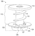
- FIG. 1 is a diagram illustrating a side, perspective view of an anchor fastener, according to an embodiment
- FIG. 2 is a diagram illustrating a top, perspective view of the anchor fastener of FIG. 1 , according to an embodiment
- FIG. 3 is a diagram illustrating a side, perspective view of an anchor fastener, according to another embodiment
- FIG. 4 is a diagram illustrating a bottom, perspective view of the anchor fastener of FIG. 3 , according to an embodiment
- FIG. 5 is a diagram illustrating an exploded side, perspective view of the anchor fastener of FIG. 3 prior to installation in a mounting surface, according to an embodiment
- FIG. 6 is a diagram illustrating a side, perspective view of the anchor fastener of FIG. 3 prior to installation in the mounting surface, according to an embodiment
- FIG. 7 is a diagram illustrating another top, perspective view of the anchor fastener of FIG. 6 prior to installation in the mounting surface, according to an embodiment
- FIG. 8 is a diagram illustrating a side view of the anchor fastener of FIG. 6 prior to installation in the mounting surface, according to an embodiment
- FIG. 9 is a diagram illustrating a side, cross-sectional view of the anchor fastener of FIG. 6 after installation in the mounting surface, according to an embodiment
- FIG. 10 is a diagram illustrating a side, perspective view of an anchor fastener with a threaded fastener, according to another embodiment
- FIG. 11 is a diagram illustrating a side, perspective view, in cross-section, of the anchor fastener and threaded fastener of FIG. 10 , according to an embodiment
- FIG. 12 is a diagrams illustrating a side, perspective view, in cross-section, of the anchor fastener of FIG. 10 , according to an embodiment
- FIG. 13 is a diagram illustrating a bottom, perspective view of the anchor fastener and threaded fastener of FIG. 10 , according to an embodiment
- FIG. 14 is a diagram illustrating a bottom, perspective view of the anchor fastener and threaded fastener of FIG. 10 prior to installation in a mounting surface, according to an embodiment.
- FIG. 15 is a diagram illustrating a side, perspective view of an anchor fastener, according to another embodiment.
- FIG. 16 is a diagram illustrating a top, perspective view of the anchor fastener of FIG. 15 .
- FIG. 17 is a diagram illustrating a partial, side, perspective view of the anchor fastener of FIG. 15 .
- FIG. 18 is a diagram illustrating a bottom view of the anchor fastener of FIG. 15 .
- FIG. 19 is a diagram illustrating top view of the anchor fastener of FIG. 15 .
- FIG. 20A is a diagram illustrating a bottom view of a distal surface of an object to be anchored, according to an embodiment.
- FIG. 20B is a diagram illustrating a bottom view of the distal surface of FIG. 20A with the anchor fastener of FIG. 15 .
- FIG. 21 is a diagram illustrating a partial, side view of the anchor fastener of FIG. 15 after installation, according to an embodiment.
- FIG. 1 is a diagram illustrating a side, perspective view of an anchor fastener 100 , according to an embodiment.
- FIG. 2 is a diagram illustrating a top, perspective view of the anchor fastener 100 of FIG. 1 .
- FIG. 3 is a diagram illustrating a side, perspective view of another embodiment of an anchor fastener 300 .
- FIG. 4 is a diagram illustrating a bottom, perspective view of the anchor fastener 300 of FIG. 3 .
- the anchor fastener 100 or 300 is a pre-assembled anchor with a threaded fastener for installation of an object or fixture onto a mounting surface.
- mounting surfaces include, but are not limited to walls, ceilings, panels, or other suitable surfaces which are formed from drywall, wallboard, wood, plywood, fiberboard, particle board, composite material, or other suitable material.
- the pre-assembled anchor is attached to an object or fixture prior to attachment of the fixture to a J-box and thus eliminates a need for pre-installation of a separate drywall anchor (e.g., marking and drilling pilot holes) when installing the fixture.
- fixtures include light fixtures, electrical fixtures, decorative fixtures, or other suitable fixtures.
- An attachment face of the object to be installed includes an anchor hole configured to receive the anchor fastener.
- the attachment face of the object is formed of sheet metal, plastic, or other suitable material. While the description herein refers to installation or attachment of a fixture, in other embodiments, the anchor fastener is used to attach an object to the mounting surface, such as a picture frame, mirror, wall hook, shelf, or other suitable object.
- the anchor fastener 100 , 300 includes an anchor body 110 , 310 and an anchor base 120 , 320 .
- the anchor fastener 100 , 300 also includes a threaded fastener 504 ( FIGS. 5, 6, 7, 8, 9, 10, and 11 ), such as a screw, bolt, or other suitable threaded fastener.
- the anchor body 110 , 310 is removably attached to the anchor base 120 , 320 .
- the anchor body 110 , 310 is configured to break away or detach from the anchor base 120 , 320 during installation of the anchor fastener 100 , 300 .
- the anchor base 120 , 320 remains in place during at least an initial installation of the anchor fastener 100 , 300 .
- the anchor body 110 , 310 includes an anchor head 112 , 312 and a generally cylindrical anchor shaft 114 , 314 extending from the anchor head 112 , 312 .
- the base 120 , 320 is located at a distal end of the shaft 114 , 314 .
- the anchor shaft 114 , 314 has a suitable length such that when the anchor body 110 , 310 is installed (See FIG. 10 ) and passes through the anchor base 120 , 320 , the anchor shaft 114 , 314 extends through a proximal face of the mounting surface but does not extend past a distal face of the mounting surface.
- the anchor shaft 314 includes a tip 428 at its distal end which is configured for self-drilling of a hole in the mounting surface into which the anchor shaft is inserted.
- the anchor shaft 114 , 314 includes one or more helical threads 116 , 316 on an outer surface configured to engage the mounting surface and drive the anchor shaft 114 , 314 into the mounting surface.
- the helical threads 116 , 316 engage the drywall and hold the anchor shaft 114 , 314 in place in the mounting surface after drilling.
- the anchor head 112 , 312 and anchor shaft 114 , 314 include a center channel 118 , 318 configured to guide a threaded fastener into the mounting surface.
- the center channel 118 , 318 extends entirely through the anchor head 112 , 312 and anchor shaft 114 , 314 .
- the center channel 118 , 318 extends a suitable distance from the anchor head 112 , 312 through the anchor shaft 114 , 314 towards the anchor base 120 , 320 such that the threaded fastener can puncture or drill through a remainder of the anchor shaft 114 , 314 into the mounting surface during installation (e.g., a user applying an installation force to the threaded fastener).
- the anchor head 112 , 312 is configured to receive a driving device (e.g., Phillips or flat-head screwdriver, hex bit, star bit, or other suitable drive mechanism) for removal of the anchor body after an initial installation.
- the anchor head 112 , 312 includes a socket or other receptacle.
- the anchor base 120 , 320 is mechanically coupled with the anchor body 110 , 310 by a plurality of bridges or webs 122 , 322 .
- the plurality of webs 122 , 322 include a suitable number of webs (e.g., 2, 3, 4, 5, or more) that are configured with a suitable thickness such that an installation force provided by a user causes the webs 122 , 322 to break away, shear, or otherwise separate from the anchor base, the anchor shaft, or both the anchor base and anchor shaft.
- the anchor base is frangibly connected to a distal end of the anchor shaft 114 , 314 , and can be separated therefrom by application of at least one of a rotational force or a linear force.
- an installation force causes i) a separation of the webs 122 , 322 , and ii) causes the self-drilling tip 428 to engage and drill into the mounting surface, and iii) installation of the anchor shaft 114 , 314 into the mounting surface.
- the anchor body 110 , 310 is generally free to rotate within the anchor base 120 , 320 and thus advance through the anchor base 120 , 320 to screw into the mounting surface.
- the webs 122 , 322 maintain the anchor body 110 , 310 in a mounting position over the anchor hole of the fixture, for example, during manufacture and/or shipment of the fixture.
- the anchor base 120 , 320 is configured to removably engage the anchor body 110 , 310 , for example, using a snap-fit engagement, friction-fit or press-fit engagement, or other suitable engagement mechanism.
- the anchor base 120 , 320 is a flat, annular ring configured to abut the object, for example, a proximal surface around an anchor hole of the object.
- the anchor base 120 , 320 includes an engagement portion 124 , 324 configured to attach the anchor fastener 100 , 300 to the object, for example, to an anchor hole of a fixture.
- the engagement portion 124 , 324 includes an annular ridge 125 , 325 having one or more slots 126 , 326 configured to provide a snap-fit engagement with the anchor hole of the fixture.
- the annular ridge 125 , 325 elastically deforms inwardly toward a center axis of the anchor base 120 , 320 (e.g., towards the center channel 118 , 318 ) when inserted through the anchor hole of the fixture and generally “snaps back” to an original shape after passing through the anchor hole.
- the annular ridge 125 , 325 includes an outwardly facing lip 127 , 327 (e.g., extending away from the center axis of the anchor base 120 , 320 ) that engages a distal surface of the anchor hole. While only two slots 326 are shown in FIG. 4 , the engagement portion 324 includes additional or fewer slots or alternatively, engagement tabs having suitable sizes, in other embodiments. In alternative embodiments, the engagement portion 324 is configured for a friction-fit or press-fit engagement to the fixture.
- the anchor fastener 100 , 300 is formed from a plastic material, such as nylon, polyoxymethylene, polypropylene, acrylonitrile butadiene styrene (ABS), polycarbonate, or other suitable material.
- the anchor fastener 100 , 300 is formed from metal, such as brass, aluminum, or steel.
- the anchor base 120 , 320 and anchor body are integrally formed as a single structure.
- the anchor base 120 , 320 and anchor body 110 , 310 are formed separately and coupled with each other after their formation.
- the anchor base 120 , 320 and anchor body are formed of different materials.
- the anchor fastener 100 , 300 is configured to be installed into the mounting surface without a separate step of installing drywall anchors into the mounting surface prior to mounting the fixture.
- the anchor fastener 100 , 300 is configured to be installed into the mounting surface after the fixture has been secured to the J-box and after proper alignment of the fixture. This helps to reduce and/or eliminate one or more of misalignment of anchor holes in the fixture with drywall anchors, misalignment of the fixture due to inaccurate measurements, and handling of multiple fasteners and tools by a user while on a ladder during installation.
- some electrical fixtures include two or more drywall anchors, each drywall anchor having two parts: an anchor that is inserted into the drywall and a screw that attaches the fixture to the drywall anchor. In this example, there are four loose parts that could potentially be dropped (and lost) by a user from the top of the ladder during installation, resulting in an increased safety hazard of going up and down the ladder.
- FIG. 5 is a diagram illustrating an exploded, side, perspective view of the anchor fastener 300 of FIG. 3 prior to installation at a location 501 in a mounting surface 502 , according to an embodiment.
- the anchor fastener 300 includes a threaded fastener 504 , such as a screw, bolt, or other suitable fastener.
- the threaded fastener 504 is a #8 X 1.25′′ Pan Philips Type AB Self Tapping Screw.
- the threaded fastener 504 is pre-installed within the center channel 318 of the anchor body 310 .
- the threaded fastener 504 is at least partially inserted into the center channel 318 of the anchor body 310 .
- the anchor base 320 is pre-installed within an anchor hole 506 of a fixture 508 which is to be attached to the mounting surface 502 .
- the anchor body 310 and threaded fastener 504 are configured to be installed into a mounting surface 502 with a wall support (e.g., a stud, brace or other suitable structure, not shown).
- the anchor shaft 314 has a suitable length (e.g., 1 ⁇ 2′′ or 3 ⁇ 4′′) such that when the anchor body 310 is installed (See FIG. 10 ) and passes through the anchor base 320 , the anchor shaft 314 does not extend past a distal face of the mounting surface 502 while the threaded fastener 504 (e.g., a self-tapping screw) screws itself into the stud and thus provides additional support.
- the threaded fastener 504 and center channel 318 are configured to transfer at least a portion of a rotational force imparted on the threaded fastener 504 to the anchor body 310 .
- a rotational force applied to the threaded fastener 504 by a user with a screw driver or other driving device is transferred to the anchor body 310 through a friction fit, press fit, threaded engagement fit, or other suitable engagement mechanism.
- the rotation of the threaded fastener 504 is transferred to the anchor body 310 , causing the tip 428 and/or anchor threads 316 to engage and install the anchor body 310 into the mounting surface 502 .
- FIG. 6 is a diagram illustrating a side, perspective view of the anchor fastener 300 prior to installation in the mounting surface 502 , according to an embodiment.
- FIG. 7 is a diagram illustrating another top, perspective view of the anchor fastener 300 of FIG. 6 prior to installation in the mounting surface 502 .
- FIG. 8 is a diagram illustrating a side view of the anchor fastener 300 of FIG. 6 prior to installation in the mounting surface 502 .
- the anchor fastener 300 is shown with the anchor base 320 coupled to the fixture 508 and the threaded fastener 504 partially inserted into the center channel 318 of the anchor body 310 .
- the anchor fastener 300 is pre-installed within the fixture 508 as shown in FIG.
- the base 320 abuts a proximal surface 910 around the anchor hole 506 of the object 508 , the annular ridge 325 extends through the anchor hole 506 , and the outwardly facing lip 327 engages a distal surface 912 of the anchor hole 506 .
- a user performs an installation of the anchor fastener 300 by engaging a driver device (e.g., a screw driver) with a head of the threaded fastener 504 .
- the user provides an installation force to the driver device, for example, pushing and/or rotating the driver device to cause the webs 322 to break.
- the installation force causes the threaded fastener 504 and the anchor body 310 to rotate.
- Rotation of the anchor body 310 causes the self-drilling tip 428 of the anchor shaft 314 to drill into the mounting surface 502 .
- the threaded fastener 504 is partially inserted or screwed into the mounting surface 502 before the webs 322 are separated.
- the threaded fastener 504 is inserted through the center channel 318 and into the mounting surface 502 , receives an installation force, and advances through the center channel 318 of the shaft during installation of the anchor fastener 300 until a head of the threaded fastener 504 engages the anchor head 312 and stops the advance of the threaded fastener 504 through the center channel 318 .
- the installation force is transferred to the anchor head 312 and the webs 322 are separated, as described above.
- FIG. 9 is a diagram illustrating a side, cross-sectional view of the anchor fastener 300 of FIG. 6 after installation in the mounting surface 502 , according to an embodiment.
- the anchor shaft 314 is separated from the webs 322 of the anchor base 320 and secured into the mounting surface 502 by the helical threads 316 .
- the anchor shaft 314 extends through a proximal face 1010 of the mounting surface but does not extend past a distal face 1012 of the mounting surface 502 .
- the anchor head 312 abuts the anchor base 320 and prevents insertion of the anchor body 310 beyond the distal face 1012 of the mounting surface 502 .
- a lateral dimension of the anchor head 312 is greater than a maximum lateral dimension of the anchor shaft 314 , which limits penetration of the anchor fastener 300 into the mounting surface 502 .
- an installation force suitable for driving the threaded fastener 504 into a stud or wall support structure is sufficient to break the webs 322 that couple the anchor base 320 to the anchor body 310 .
- the threaded fastener 504 is removable after installation, for example, using a screwdriver, driving device, or other suitable extraction tool.
- the anchor body 310 is removable from the mounting surface, for example, using a screwdriver or other suitable extraction tool.
- the threaded fastener 504 and the anchor body 310 have a same socket or receptacle configuration (e.g., Phillips, hex, etc.) or are otherwise configured for removal using a same tool.
- FIG. 10 is a diagram illustrating a side, perspective view of an anchor fastener 1200 with a threaded fastener 1250 , according to another embodiment.
- FIG. 11 is a diagram illustrating a side, perspective view, in cross-section, of the anchor fastener 1200 and threaded fastener 1250 of FIG. 10 , according to an embodiment.
- FIG. 12 is a diagram illustrating a side, perspective view, in cross-section, of the anchor fastener 1200 of FIG. 10 , according to an embodiment.
- FIG. 13 is a diagram illustrating a bottom, perspective view of the anchor fastener 1200 and threaded fastener 1250 of FIG. 10 , according to an embodiment.
- FIG. 14 is a diagram illustrating a bottom, perspective view of the anchor fastener 1200 and threaded fastener 1250 of FIG. 10 coupled to a fixture 1602 prior to installation in a mounting surface (not shown), according to an embodiment.
- the anchor fastener 1200 includes an anchor body 1210 and an anchor base 1220 at a distal end of the anchor body 1210 .
- the anchor body 1210 includes an anchor head 1212 and an anchor shaft 1214 having one or more helical threads 1216 and a self-drilling tip 1228 .
- the anchor base 1220 is coupled to the anchor shaft 1214 of the anchor body 1210 by one or more frangible webs 1222 .
- the anchor body 1210 includes a center channel 1318 configured to guide the threaded fastener 1250 into the mounting surface.
- the center channel 1318 includes a receptacle 1418 , an unthreaded portion 1330 , and a threaded portion 1332 .
- the receptacle 1418 is configured to receive a driving device (e.g., Phillips or flat-head screwdriver, hex key or hex bit, star bit, or other suitable drive mechanism) for removal of the anchor body 1210 after an initial installation.
- a driving device e.g., Phillips or flat-head screwdriver, hex key or hex bit, star bit, or other suitable drive mechanism
- the receptacle 1418 is a Phillips compatible slot, a flat-head slot, or a hexagonal shape.
- the receptacle 1418 has a star shape having four, five, six, or another suitable number of points.
- the threaded portion 1332 provides a threaded engagement fit with the threaded fastener 1250 to secure the threaded fastener 1250 prior to installation.
- the unthreaded portion 1330 provides a reduced friction area within the center channel 1318 to reduce an installation force required to install the threaded fastener 1250 .
- the unthreaded portion 1330 is omitted and the threaded portion 1332 extends along an entire length, or substantially the entire length, of the center channel 1318 .
- the anchor base 1220 is a flat, annular ring and includes an engagement portion 1224 configured to attach the anchor fastener 1200 to the fixture 1602 .
- the engagement portion 1224 includes an annular ridge 1225 having one or more slots 1226 configured to provide a snap-fit engagement with an anchor hole (not shown) of the fixture 1602 .
- the annular ridge 1225 includes an outwardly facing lip 1227 that engages a distal surface of the anchor hole.
- FIG. 15 is a diagram illustrating a side, perspective view of an anchor fastener 1500 , according to an embodiment.
- FIG. 16 is a diagram illustrating a top, perspective view of the anchor fastener 1500 .
- FIG. 17 is a diagram illustrating a partial, side, perspective view of the anchor fastener 1500 .
- FIG. 18 is a diagram illustrating a bottom view of the anchor fastener 1500 .
- FIG. 19 is a diagram illustrating top view of the anchor fastener 1500 .
- FIG. 20A is a diagram illustrating a bottom view of a distal surface of an object to be anchored, according to an embodiment.
- FIG. 20B is a diagram illustrating a bottom view of the distal surface of FIG. 20A with the anchor fastener of FIG. 15 .
- FIG. 21 is a diagram illustrating a partial, side view of the anchor fastener of FIG. 15 after installation, according to an embodiment.
- the anchor fastener 1500 is similar to the anchor fastener 100 and anchor fastener 300 , with one or more differences and features described below.
- the anchor fastener 1500 is a pre-assembled anchor for installation of an object or fixture onto a mounting surface.
- the anchor fastener 1500 omits the threaded fastener (e.g. fastener 504 ) utilized by the anchor fasteners 100 and 300 .
- the anchor fastener 1500 includes an anchor body 1510 , an anchor base 1520 , and at least one frangible portion 1822 .
- the anchor body 1510 includes a head 1512 and a generally cylindrical shaft 1514 that extends from the head 1512 .
- a helical thread 1516 of the shaft 1514 extends along an outer surface of the shaft 1514 towards the distal end of the shaft.
- the shaft 1514 includes a tip 1828 at its distal end which is configured for self-drilling of a hole in the mounting surface 2100 into which the shaft 1514 is to be installed.
- the anchor body 1500 is removably attached to the anchor base 1520 by the frangible portion 1822 .
- the frangible portion 1822 is configured to frangibly connect the shaft 1514 to the base 1520 and thus, to break away or detach from the anchor base 1520 during installation of the shaft 1514 into the mounting surface 2100 .
- the frangible portion 1822 is separable from at least one of the base 1520 and the shaft 1514 under application of a force to the shaft 1514 .
- a user provides at least a rotational installation force to the shaft 1514 by turning a screwdriver, screw gun, or other suitable driving device with a suitable bit (e.g., Phillips or flat-head screwdriver, hex bit, star bit) placed into a corresponding receptacle 1618 , causing the frangible portions 1822 to break free.
- a suitable bit e.g., Phillips or flat-head screwdriver, hex bit, star bit
- a user pushes along a central axis of the shaft 1514 to break the frangible portions free before providing the rotational installation force.
- the user provides the rotational installation force immediately after breaking the frangible portions.
- the same installation force that installs the shaft into the mounting surface breaks the frangible portions free, which simplifies installation of the anchor fastener 1500 .
- the rotational installation force causes i) a separation of the at least one frangible portion 1822 , ii) the self-drilling tip 1828 to engage and drill into the mounting surface 2100 , and iii) installation of the shaft 1514 into the mounting surface 2100 .
- the anchor base 1520 includes a distal surface 1802 and an engagement portion 1524 configured to engage an object 2000 ( FIG. 20 ) to be anchored to a mounting surface 2100 ( FIG. 21 ) and configured to hold the anchor fastener 1500 to the object 2000 before installation of the shaft 1514 through the object 2000 and into the mounting surface 2100 .
- the engagement portion 1524 provides a snap-fit engagement with the object 2000 , in a manner similar to the engagement portion 124 .
- the distal surface 1802 of the base 1520 extends away from a center axis of the shaft 1514 beyond an anchor hole 2002 ( FIG. 20 ) of the object 2000 and is configured to abut a proximal surface of the object around the anchor hole.
- the base 1520 includes a thread guide 1528 configured to support the helical thread 1516 during installation of the shaft 1514 .
- the thread guide 1528 is configured to stabilize a rotational axis of the shaft 1514 during installation of the shaft 1514 into the mounting surface 2100 .
- the thread guide 1528 holds the body 1510 in a suitable position while the body 1510 is installed and screwed into the mounting surface 2100 .
- the thread guide 1528 includes a plurality of engagement surfaces 1528 A, 1528 B, and 1528 C that engage the helical thread 1516 during installation.
- the engagement surfaces 1528 A, 1528 B, and 1528 C are formed at different distances from the base 1520 , for example, at different distances according to a thread pitch of the helical thread 1516 .
- the engagement surfaces 1528 are configured as threads of a nut that guide the threaded shaft 1514 during installation to keep the shaft 1514 suitably aligned with the mounting surface 2100 (e.g., perpendicular or normal to the mounting surface).
- the mounting surface 2100 e.g., perpendicular or normal to the mounting surface.
- the plurality of engagement surfaces 1528 include at least three engagement surfaces 1528 A, 1528 B, and 1528 C that extend inwards from the base 1520 towards respective frangible portions 1822 A, 1822 B, and 1822 C that frangibly connect the shaft 1514 to the base 1520 .
- the engagement surfaces 1528 include two, four, five, or more engagement surfaces.
- the thread guides 1528 are configured to be flex downwards (towards the mounting surface 2100 ) when a predetermined amount of force is applied. For example, the thread guides 1528 flex downwards and towards the center of the anchor hole when the head 1512 presses an upper surface of the thread guides 1528 so that the thread guides 1528 do not prevent shaft 1514 from being fully installed into the mounting surface 2100 .
- the anchor fastener 1500 includes the engagement portion 1524 which is configured to prevent rotation of the base 1520 relative to the object 2000 to be anchored.
- the engagement portion 1524 includes flat portions 1524 A, 1524 B, 1524 C, 1524 D that engage corresponding notches 2004 A, 2004 B, 2004 C, and 2004 D in the object 2000 to be anchored.
- the engagement portion 1524 includes one, two, three, five, or more flat portions.
- the engagement portion 1524 has a different suitable shape that restricts rotation of the base 1520 within the object 2000 to be anchored (e.g., a square shape, hexagon shape). In the embodiment shown in FIG.
- the notches 2004 are formed separately from the anchor hole 2002 . In other embodiments, one or more of the notches 2004 are integrally formed with the anchor hole 2002 . In an embodiment, for example, the anchor hole 2002 and the notches 2004 are formed as a single hole within the object 2000 .
- the head 1510 includes a flexible portion 1912 configured to flex and resist rotation of the shaft 1514 , for example, to reduce a harsh “stop” sensation felt by the user when the head 1512 reaches the base 1520 during installation.
- the flexible portion 1912 includes elongated circumferential fingers 1912 A, 1912 B, 1912 C, and 1912 D that flex during installation.
- the flexible portion 1912 flexes about the rotational axis of the shaft 1514 , for example, so that a tip 1914 of a the finger 1912 A flexes towards a “knuckle” 1913 of an adjacent finger 1912 B.
- the flexible portion 1912 flexes away from a proximal surface of the base 1520 and in a direction parallel to the shaft 1514 .
- the base 1520 includes one or more protrusions 1526 that protrude towards the flexible portion 1912 .
- the flexible portion 1912 is configured to engage the protrusion 1526 and flex to resist and slow rotation of the shaft 1514 .
- the anchor fastener 1500 includes four elongated circumferential fingers 1912 A, 1912 B, 1912 C, and 1912 D arranged in a plane perpendicular to the shaft 1514 where the fingers rotate within the plane.
- the protrusion 1526 is configured to prevent further rotation of the shaft 1514 at a predetermined installation depth of the shaft 1514 . In some embodiments, the protrusion 1526 prevents further rotation of the shaft 1514 to prevent the helical thread 1516 from “stripping out” the mounting surface 2100 . For example, where the mounting surface 2100 is drywall (or other relatively soft material), additional rotations of the helical thread 1516 begin to weaken and break up the drywall, reducing the effectiveness of the drywall anchor 1500 .
- a height of the thread guides 1528 is set based on a height of the protrusion 1526 from the base 1520 and an amount of rotation of the flexible portions 1912 during the installation so that the elongated circumferential fingers 1912 engage the protrusion 1526 at a desired maximum installation depth of the shaft 1514 .
- the thread guides 1528 have a height that places the knuckle portion 1913 of the flexible portions 1912 directly over the protrusion 1526 when the frangible portions 1822 have broken and the self-drilling tip 1828 has started to engage the mounting surface 2100 , and thus, after the three full rotations, the knuckle portion 1913 engages and abuts the protrusion 1526 .
Landscapes
- Engineering & Computer Science (AREA)
- General Engineering & Computer Science (AREA)
- Mechanical Engineering (AREA)
- Physics & Mathematics (AREA)
- Geometry (AREA)
- Life Sciences & Earth Sciences (AREA)
- Chemical & Material Sciences (AREA)
- Dispersion Chemistry (AREA)
- Wood Science & Technology (AREA)
- Connection Of Plates (AREA)
Abstract
Description
Claims (19)
Priority Applications (1)
| Application Number | Priority Date | Filing Date | Title |
|---|---|---|---|
| US15/871,841 US10539171B2 (en) | 2015-01-26 | 2018-01-15 | Anchor fastener |
Applications Claiming Priority (3)
| Application Number | Priority Date | Filing Date | Title |
|---|---|---|---|
| US201562107719P | 2015-01-26 | 2015-01-26 | |
| US15/006,953 US9869336B2 (en) | 2015-01-26 | 2016-01-26 | Anchor fastener |
| US15/871,841 US10539171B2 (en) | 2015-01-26 | 2018-01-15 | Anchor fastener |
Related Parent Applications (1)
| Application Number | Title | Priority Date | Filing Date |
|---|---|---|---|
| US15/006,953 Continuation-In-Part US9869336B2 (en) | 2015-01-26 | 2016-01-26 | Anchor fastener |
Publications (2)
| Publication Number | Publication Date |
|---|---|
| US20180156255A1 US20180156255A1 (en) | 2018-06-07 |
| US10539171B2 true US10539171B2 (en) | 2020-01-21 |
Family
ID=62242970
Family Applications (1)
| Application Number | Title | Priority Date | Filing Date |
|---|---|---|---|
| US15/871,841 Active 2036-07-29 US10539171B2 (en) | 2015-01-26 | 2018-01-15 | Anchor fastener |
Country Status (1)
| Country | Link |
|---|---|
| US (1) | US10539171B2 (en) |
Families Citing this family (7)
| Publication number | Priority date | Publication date | Assignee | Title |
|---|---|---|---|---|
| US11236775B1 (en) * | 2018-07-13 | 2022-02-01 | Harvel Crumley | Sill plate anchor assembly |
| US11333186B2 (en) * | 2019-03-27 | 2022-05-17 | Component 2.0 A/S | Dowel pin for easy assembly and high accuracy |
| USD913782S1 (en) * | 2019-06-07 | 2021-03-23 | Sps Technologies, Llc | Blind fastener sleeve |
| US11209037B2 (en) * | 2019-07-03 | 2021-12-28 | David Adams | Screw and anchor assembly |
| KR102278685B1 (en) * | 2019-07-15 | 2021-07-16 | 김인식 | Earthing Bolt |
| DE102020204176A1 (en) * | 2020-03-31 | 2021-09-30 | Witte Automotive Gmbh | Fastener |
| TWI780510B (en) * | 2020-11-02 | 2022-10-11 | 鋐昇實業股份有限公司 | Rotary self-drilling screw having detachable drill bit and lock function |
Citations (66)
| Publication number | Priority date | Publication date | Assignee | Title |
|---|---|---|---|---|
| US1370319A (en) | 1919-05-08 | 1921-03-01 | Edward Ogden J | Spring toggle-bolt |
| US3170361A (en) | 1962-08-06 | 1965-02-23 | Rudolph M Vaughn | Toggle bolt |
| US3213746A (en) | 1963-10-24 | 1965-10-26 | James E Dwyer | Anchoring socket for screw type fasteners |
| US3283641A (en) | 1964-06-04 | 1966-11-08 | John B Wagner | Soft screw anchor |
| US3641866A (en) * | 1969-02-07 | 1972-02-15 | Aackersberg Mortensen | Tubular anchoring member |
| US3651734A (en) | 1969-04-23 | 1972-03-28 | Mechanical Plastics Corp | Expansible fastener |
| US3706139A (en) | 1971-08-12 | 1972-12-19 | George C Brumlik | Construction elements for the assembly of molecular models, toys and the like |
| US3735665A (en) | 1970-03-16 | 1973-05-29 | L Mortensen | Expandable screw anchoring device and a spacing member therefor |
| US3770036A (en) | 1972-01-31 | 1973-11-06 | Lamson & Sessions Co | Fastener |
| US3869959A (en) | 1973-04-26 | 1975-03-11 | George A Moen | Fastener device |
| US3959853A (en) | 1974-02-14 | 1976-06-01 | Maryan Talan | Fastening peg and method of making same |
| US4309136A (en) | 1978-07-10 | 1982-01-05 | Bassan & Cie. | Fastening device |
| US4601625A (en) | 1984-05-11 | 1986-07-22 | Illinois Tool Works Inc. | Self drilling threaded insert for drywall |
| US4770583A (en) | 1984-12-20 | 1988-09-13 | Stig Danielsson | Fastening means for fixing of a screw or the like in a hole preferably made in a plaster board |
| US4878791A (en) | 1987-10-19 | 1989-11-07 | Nifco Inc. | Expanding plastic fastener |
| US4886405A (en) | 1989-01-27 | 1989-12-12 | Blomberg Ingvar M | Wall mounting device |
| US5007780A (en) | 1989-04-17 | 1991-04-16 | Hilti Aktiengesellschaft | Attachment member anchored by hardenable mass to panel-shaped structural component |
| US5160225A (en) | 1991-08-23 | 1992-11-03 | Chern T P | Structure of a self-drilling threaded insert for use on drywall |
| US5219452A (en) | 1991-08-14 | 1993-06-15 | Akio Yamamoto | Screw or nail sustainer for mounting objects to a drilled hole in a wall |
| US5226768A (en) | 1991-07-01 | 1993-07-13 | Speer Lane L | Anchor bolt construction |
| US5234299A (en) | 1987-08-03 | 1993-08-10 | Giannuzzi Louis | Self-drilling anchor |
| US5267423A (en) | 1987-08-03 | 1993-12-07 | Giannuzzi Louis | Self-drilling anchor and bearing plate assembly |
| US5275519A (en) | 1992-04-07 | 1994-01-04 | Elisabeth Hainke | Anchor bolt |
| US5308203A (en) | 1992-09-22 | 1994-05-03 | Titan Technologies, Inc. | Saw tipped anchor insert |
| US5536121A (en) | 1992-09-22 | 1996-07-16 | Titan Technologies, Inc. | Anchor insert |
| US5690454A (en) | 1992-11-23 | 1997-11-25 | Dry Dock Industries, Inc. | Anchoring retainer for threaded fasteners |
| US5694666A (en) | 1995-11-27 | 1997-12-09 | Illinois Tool Works Inc. | Clip |
| US5833415A (en) | 1992-09-22 | 1998-11-10 | Titan Technology, Inc. | Anchor insert improvement |
| US5876169A (en) | 1997-04-21 | 1999-03-02 | W. A. Deutsher Pty Ltd | Threaded anchor |
| US6065918A (en) | 1999-07-01 | 2000-05-23 | Adams; Richard R. | Self-drilling blind setting rivet |
| US6164884A (en) | 1998-08-17 | 2000-12-26 | Mayr; Alfred Friedrich | Anchor with spreading elements |
| US6186716B1 (en) | 1998-11-12 | 2001-02-13 | Westerlund Products Corporation | Anchor bolt |
| US6406236B1 (en) | 2001-03-12 | 2002-06-18 | Fourslides, Inc. | Panel fastener and method of manufacture thereof |
| US6494653B2 (en) | 2001-04-17 | 2002-12-17 | Emerson Electric Company | Wall anchor |
| US6565303B1 (en) * | 2001-07-16 | 2003-05-20 | Olympic Manufacturing Group, Inc. | Washer and assembly of same employing a securing member |
| US6679661B2 (en) | 2002-04-18 | 2004-01-20 | Joker Industrial Co., Ltd. | Fastener for fragile boards |
| US20050084360A1 (en) | 2003-10-10 | 2005-04-21 | Panasik Cheryl L. | Self-drilling anchor |
| US6926483B2 (en) | 2003-07-22 | 2005-08-09 | Bollhoff Verbindungstechnik Gmbh | Joining assembly for joining a pair of structural members |
| US20050271491A1 (en) | 2002-09-04 | 2005-12-08 | Newfrey Llc | Fastening element, particularly for blind rivets |
| US20060120822A1 (en) | 2004-12-02 | 2006-06-08 | Kaye Gordon E | Self-drilling hollow wall anchor |
| US7070376B1 (en) | 1999-12-14 | 2006-07-04 | Simpson Strong-Tie Company, Inc. | Self-drilling, self-anchoring fastener for concrete |
| US20060165506A1 (en) | 2004-02-05 | 2006-07-27 | Panasik Cheryl L | Anchor |
| US20060228188A1 (en) | 2004-09-27 | 2006-10-12 | Alliance Metal Corporation | Self-drilling wall anchor device and method for using the same |
| US7137766B2 (en) | 2003-12-16 | 2006-11-21 | Burton Weinstein | Screw and plastic part unit |
| US7237994B2 (en) | 2003-07-03 | 2007-07-03 | Turner Intellectual Property Limited | Wall plug |
| US7261505B2 (en) | 2004-09-10 | 2007-08-28 | Illinois Tool Works Inc. | Self-drilling anchor |
| US7290972B2 (en) | 2003-01-29 | 2007-11-06 | Societe De Prospection Et D'inventions Techniques Spit | Screw anchor for friable material |
| US20080292421A1 (en) | 2007-05-22 | 2008-11-27 | Chin Hou Lin | Self-drilling wall anchor device |
| US7465137B2 (en) | 2006-07-11 | 2008-12-16 | Mnp Corporation | Threaded fastener with retainer |
| US7604446B2 (en) | 2006-03-25 | 2009-10-20 | Honeywell International Inc. | Housing mountable with drywall anchor |
| US7615407B1 (en) | 2008-07-02 | 2009-11-10 | National Semiconductor Corporation | Methods and systems for packaging integrated circuits with integrated passive components |
| US7654781B2 (en) | 2002-12-11 | 2010-02-02 | Cobra Fixations Cie Ltee-Cobra Anchors Co., Ltd | Anchor for hollow walls |
| US7713010B2 (en) | 2006-09-13 | 2010-05-11 | Ming Chia Cheng | Self-drilling wall anchor device |
| US7748089B2 (en) | 2008-01-15 | 2010-07-06 | Illinois Tool Works Inc. | Auger clip assembly |
| US7815407B2 (en) | 2007-09-14 | 2010-10-19 | Paul Kucharyson | Self-drilling anchor |
| US7934895B2 (en) | 2003-10-10 | 2011-05-03 | Illinois Tool Works Inc. | Self-drilling anchor |
| US8057147B2 (en) | 2008-07-03 | 2011-11-15 | Illinois Tool Works Inc | Self-drilling anchor |
| US8070405B2 (en) | 2007-03-08 | 2011-12-06 | Eran Hazout | Self drilling bolt with anchor |
| US8142122B2 (en) | 2006-01-17 | 2012-03-27 | Cobra Fixations Cie Ltee-Cobra Anchors Co. Ltd | Plastic anchor for drywall, plaster, brick and concrete |
| US20120183372A1 (en) | 2011-01-13 | 2012-07-19 | Hilti Aktiengesellschaft | Screw anchor and method for producing a screw anchor |
| US20120328392A1 (en) | 2011-06-21 | 2012-12-27 | Agostino Difante | Toggle bolt fastener and method of operation |
| US8376679B2 (en) | 2010-01-29 | 2013-02-19 | Black & Decker Inc. | Wall anchor system |
| US8404065B2 (en) | 2011-06-28 | 2013-03-26 | Robert W. Miller | Method and apparatus for installing a surface conforming drywall anchor |
| US8602703B1 (en) | 2010-02-24 | 2013-12-10 | Michael Rich | Anchor for wall and other structures |
| US8740527B2 (en) | 2012-07-12 | 2014-06-03 | Ming-Chia Cheng | Self-drilling wall anchor device |
| US20140225486A1 (en) | 2013-02-05 | 2014-08-14 | Douglas A. English | Mounting Fixture And Method For Using Same |
-
2018
- 2018-01-15 US US15/871,841 patent/US10539171B2/en active Active
Patent Citations (67)
| Publication number | Priority date | Publication date | Assignee | Title |
|---|---|---|---|---|
| US1370319A (en) | 1919-05-08 | 1921-03-01 | Edward Ogden J | Spring toggle-bolt |
| US3170361A (en) | 1962-08-06 | 1965-02-23 | Rudolph M Vaughn | Toggle bolt |
| US3213746A (en) | 1963-10-24 | 1965-10-26 | James E Dwyer | Anchoring socket for screw type fasteners |
| US3283641A (en) | 1964-06-04 | 1966-11-08 | John B Wagner | Soft screw anchor |
| US3641866A (en) * | 1969-02-07 | 1972-02-15 | Aackersberg Mortensen | Tubular anchoring member |
| US3651734A (en) | 1969-04-23 | 1972-03-28 | Mechanical Plastics Corp | Expansible fastener |
| US3735665A (en) | 1970-03-16 | 1973-05-29 | L Mortensen | Expandable screw anchoring device and a spacing member therefor |
| US3706139A (en) | 1971-08-12 | 1972-12-19 | George C Brumlik | Construction elements for the assembly of molecular models, toys and the like |
| US3770036A (en) | 1972-01-31 | 1973-11-06 | Lamson & Sessions Co | Fastener |
| US3869959A (en) | 1973-04-26 | 1975-03-11 | George A Moen | Fastener device |
| US3959853A (en) | 1974-02-14 | 1976-06-01 | Maryan Talan | Fastening peg and method of making same |
| US4309136A (en) | 1978-07-10 | 1982-01-05 | Bassan & Cie. | Fastening device |
| US4601625A (en) | 1984-05-11 | 1986-07-22 | Illinois Tool Works Inc. | Self drilling threaded insert for drywall |
| US4770583A (en) | 1984-12-20 | 1988-09-13 | Stig Danielsson | Fastening means for fixing of a screw or the like in a hole preferably made in a plaster board |
| US5234299A (en) | 1987-08-03 | 1993-08-10 | Giannuzzi Louis | Self-drilling anchor |
| US5267423A (en) | 1987-08-03 | 1993-12-07 | Giannuzzi Louis | Self-drilling anchor and bearing plate assembly |
| US4878791A (en) | 1987-10-19 | 1989-11-07 | Nifco Inc. | Expanding plastic fastener |
| US4886405A (en) | 1989-01-27 | 1989-12-12 | Blomberg Ingvar M | Wall mounting device |
| US5007780A (en) | 1989-04-17 | 1991-04-16 | Hilti Aktiengesellschaft | Attachment member anchored by hardenable mass to panel-shaped structural component |
| US5226768A (en) | 1991-07-01 | 1993-07-13 | Speer Lane L | Anchor bolt construction |
| US5219452A (en) | 1991-08-14 | 1993-06-15 | Akio Yamamoto | Screw or nail sustainer for mounting objects to a drilled hole in a wall |
| US5160225A (en) | 1991-08-23 | 1992-11-03 | Chern T P | Structure of a self-drilling threaded insert for use on drywall |
| US5275519A (en) | 1992-04-07 | 1994-01-04 | Elisabeth Hainke | Anchor bolt |
| US5833415A (en) | 1992-09-22 | 1998-11-10 | Titan Technology, Inc. | Anchor insert improvement |
| US5308203A (en) | 1992-09-22 | 1994-05-03 | Titan Technologies, Inc. | Saw tipped anchor insert |
| US5536121A (en) | 1992-09-22 | 1996-07-16 | Titan Technologies, Inc. | Anchor insert |
| US5690454A (en) | 1992-11-23 | 1997-11-25 | Dry Dock Industries, Inc. | Anchoring retainer for threaded fasteners |
| US5694666A (en) | 1995-11-27 | 1997-12-09 | Illinois Tool Works Inc. | Clip |
| US5876169A (en) | 1997-04-21 | 1999-03-02 | W. A. Deutsher Pty Ltd | Threaded anchor |
| US6164884A (en) | 1998-08-17 | 2000-12-26 | Mayr; Alfred Friedrich | Anchor with spreading elements |
| US6186716B1 (en) | 1998-11-12 | 2001-02-13 | Westerlund Products Corporation | Anchor bolt |
| US6065918A (en) | 1999-07-01 | 2000-05-23 | Adams; Richard R. | Self-drilling blind setting rivet |
| US7070376B1 (en) | 1999-12-14 | 2006-07-04 | Simpson Strong-Tie Company, Inc. | Self-drilling, self-anchoring fastener for concrete |
| US6406236B1 (en) | 2001-03-12 | 2002-06-18 | Fourslides, Inc. | Panel fastener and method of manufacture thereof |
| US6494653B2 (en) | 2001-04-17 | 2002-12-17 | Emerson Electric Company | Wall anchor |
| US6565303B1 (en) * | 2001-07-16 | 2003-05-20 | Olympic Manufacturing Group, Inc. | Washer and assembly of same employing a securing member |
| US6679661B2 (en) | 2002-04-18 | 2004-01-20 | Joker Industrial Co., Ltd. | Fastener for fragile boards |
| US20050271491A1 (en) | 2002-09-04 | 2005-12-08 | Newfrey Llc | Fastening element, particularly for blind rivets |
| US7654781B2 (en) | 2002-12-11 | 2010-02-02 | Cobra Fixations Cie Ltee-Cobra Anchors Co., Ltd | Anchor for hollow walls |
| US7290972B2 (en) | 2003-01-29 | 2007-11-06 | Societe De Prospection Et D'inventions Techniques Spit | Screw anchor for friable material |
| US7237994B2 (en) | 2003-07-03 | 2007-07-03 | Turner Intellectual Property Limited | Wall plug |
| US6926483B2 (en) | 2003-07-22 | 2005-08-09 | Bollhoff Verbindungstechnik Gmbh | Joining assembly for joining a pair of structural members |
| US20050084360A1 (en) | 2003-10-10 | 2005-04-21 | Panasik Cheryl L. | Self-drilling anchor |
| US7934895B2 (en) | 2003-10-10 | 2011-05-03 | Illinois Tool Works Inc. | Self-drilling anchor |
| US7137766B2 (en) | 2003-12-16 | 2006-11-21 | Burton Weinstein | Screw and plastic part unit |
| US20060165506A1 (en) | 2004-02-05 | 2006-07-27 | Panasik Cheryl L | Anchor |
| US7261505B2 (en) | 2004-09-10 | 2007-08-28 | Illinois Tool Works Inc. | Self-drilling anchor |
| US20060228188A1 (en) | 2004-09-27 | 2006-10-12 | Alliance Metal Corporation | Self-drilling wall anchor device and method for using the same |
| US20060120822A1 (en) | 2004-12-02 | 2006-06-08 | Kaye Gordon E | Self-drilling hollow wall anchor |
| US8142122B2 (en) | 2006-01-17 | 2012-03-27 | Cobra Fixations Cie Ltee-Cobra Anchors Co. Ltd | Plastic anchor for drywall, plaster, brick and concrete |
| US20120257944A1 (en) | 2006-01-17 | 2012-10-11 | Cobra Fixations Cie Ltee-Cobra Anchors Co. Ltd | Plastic anchor for drywall, plaster, brick and concrete |
| US7604446B2 (en) | 2006-03-25 | 2009-10-20 | Honeywell International Inc. | Housing mountable with drywall anchor |
| US7465137B2 (en) | 2006-07-11 | 2008-12-16 | Mnp Corporation | Threaded fastener with retainer |
| US7713010B2 (en) | 2006-09-13 | 2010-05-11 | Ming Chia Cheng | Self-drilling wall anchor device |
| US8070405B2 (en) | 2007-03-08 | 2011-12-06 | Eran Hazout | Self drilling bolt with anchor |
| US20080292421A1 (en) | 2007-05-22 | 2008-11-27 | Chin Hou Lin | Self-drilling wall anchor device |
| US7815407B2 (en) | 2007-09-14 | 2010-10-19 | Paul Kucharyson | Self-drilling anchor |
| US7748089B2 (en) | 2008-01-15 | 2010-07-06 | Illinois Tool Works Inc. | Auger clip assembly |
| US7615407B1 (en) | 2008-07-02 | 2009-11-10 | National Semiconductor Corporation | Methods and systems for packaging integrated circuits with integrated passive components |
| US8057147B2 (en) | 2008-07-03 | 2011-11-15 | Illinois Tool Works Inc | Self-drilling anchor |
| US8376679B2 (en) | 2010-01-29 | 2013-02-19 | Black & Decker Inc. | Wall anchor system |
| US8602703B1 (en) | 2010-02-24 | 2013-12-10 | Michael Rich | Anchor for wall and other structures |
| US20120183372A1 (en) | 2011-01-13 | 2012-07-19 | Hilti Aktiengesellschaft | Screw anchor and method for producing a screw anchor |
| US20120328392A1 (en) | 2011-06-21 | 2012-12-27 | Agostino Difante | Toggle bolt fastener and method of operation |
| US8404065B2 (en) | 2011-06-28 | 2013-03-26 | Robert W. Miller | Method and apparatus for installing a surface conforming drywall anchor |
| US8740527B2 (en) | 2012-07-12 | 2014-06-03 | Ming-Chia Cheng | Self-drilling wall anchor device |
| US20140225486A1 (en) | 2013-02-05 | 2014-08-14 | Douglas A. English | Mounting Fixture And Method For Using Same |
Also Published As
| Publication number | Publication date |
|---|---|
| US20180156255A1 (en) | 2018-06-07 |
Similar Documents
| Publication | Publication Date | Title |
|---|---|---|
| US10539171B2 (en) | Anchor fastener | |
| US9869336B2 (en) | Anchor fastener | |
| US9574593B2 (en) | Two-way fastener and method | |
| US5039262A (en) | Self-drilling wall anchor | |
| EP1817504B1 (en) | Self-drilling hollow wall anchor | |
| US20090310371A1 (en) | Mounting Bracket for Electrical Junction Box, Luminaire or the Like | |
| US5942726A (en) | Self-attaching electrical box | |
| US9145908B2 (en) | Blind fastener | |
| US20070183866A1 (en) | Self locating wall fastener | |
| US20020118545A1 (en) | Quick-install, flush-mount bracket for light and other fixtures | |
| EP2920476B1 (en) | Combination hanger fastener | |
| US20200063783A1 (en) | Reverse-thread insert anchor for masonry applications | |
| US5467571A (en) | Snap fastener and method of installing removable trim | |
| US5865584A (en) | Plywood fastener for affixing plywood to light gauge sheet metal | |
| GB2124318A (en) | A screw threaded fastener and fastened assembly | |
| EP0416183A1 (en) | Anchor-fixing | |
| US20130031771A1 (en) | Duplex Toggle Bolt Assembly | |
| HU220686B1 (en) | Fitting component | |
| US11732464B2 (en) | Securing assembly | |
| EP1134437B1 (en) | Screw with a threaded head | |
| US20130145716A1 (en) | Building with panels of dissimilar materials | |
| EP2607719B1 (en) | Blind fastener | |
| US8684648B2 (en) | Fastening system for assembling panels of dissimilar materials | |
| JP6951193B2 (en) | Tightening torque control tool and combination of tightening torque control tool and fastener | |
| JP2764040B2 (en) | Fixture for flexible boards |
Legal Events
| Date | Code | Title | Description |
|---|---|---|---|
| FEPP | Fee payment procedure |
Free format text: ENTITY STATUS SET TO UNDISCOUNTED (ORIGINAL EVENT CODE: BIG.); ENTITY STATUS OF PATENT OWNER: SMALL ENTITY |
|
| AS | Assignment |
Owner name: GOOD EARTH LIGHTING, INC., ILLINOIS Free format text: ASSIGNMENT OF ASSIGNORS INTEREST;ASSIGNORS:KOWALENKO, ALEXANDER;SERAK, CHRISTOPHER J.;REEL/FRAME:044659/0030 Effective date: 20180118 |
|
| FEPP | Fee payment procedure |
Free format text: ENTITY STATUS SET TO SMALL (ORIGINAL EVENT CODE: SMAL); ENTITY STATUS OF PATENT OWNER: SMALL ENTITY |
|
| STPP | Information on status: patent application and granting procedure in general |
Free format text: DOCKETED NEW CASE - READY FOR EXAMINATION |
|
| STPP | Information on status: patent application and granting procedure in general |
Free format text: NOTICE OF ALLOWANCE MAILED -- APPLICATION RECEIVED IN OFFICE OF PUBLICATIONS |
|
| STPP | Information on status: patent application and granting procedure in general |
Free format text: PUBLICATIONS -- ISSUE FEE PAYMENT RECEIVED |
|
| STCF | Information on status: patent grant |
Free format text: PATENTED CASE |
|
| AS | Assignment |
Owner name: OLD NATIONAL BANK, ILLINOIS Free format text: SECURITY INTEREST;ASSIGNOR:GOOD EARTH LIGHTING, INC.;REEL/FRAME:059665/0938 Effective date: 20220420 |
|
| MAFP | Maintenance fee payment |
Free format text: PAYMENT OF MAINTENANCE FEE, 4TH YR, SMALL ENTITY (ORIGINAL EVENT CODE: M2551); ENTITY STATUS OF PATENT OWNER: SMALL ENTITY Year of fee payment: 4 |