EP1500829A1 - Screw connecting arrangement for connecting two pieces - Google Patents
Screw connecting arrangement for connecting two pieces Download PDFInfo
- Publication number
- EP1500829A1 EP1500829A1 EP04009585A EP04009585A EP1500829A1 EP 1500829 A1 EP1500829 A1 EP 1500829A1 EP 04009585 A EP04009585 A EP 04009585A EP 04009585 A EP04009585 A EP 04009585A EP 1500829 A1 EP1500829 A1 EP 1500829A1
- Authority
- EP
- European Patent Office
- Prior art keywords
- screw
- arrangement according
- blind rivet
- connection arrangement
- screw connection
- Prior art date
- Legal status (The legal status is an assumption and is not a legal conclusion. Google has not performed a legal analysis and makes no representation as to the accuracy of the status listed.)
- Granted
Links
Images

Classifications
-
- F—MECHANICAL ENGINEERING; LIGHTING; HEATING; WEAPONS; BLASTING
- F16—ENGINEERING ELEMENTS AND UNITS; GENERAL MEASURES FOR PRODUCING AND MAINTAINING EFFECTIVE FUNCTIONING OF MACHINES OR INSTALLATIONS; THERMAL INSULATION IN GENERAL
- F16B—DEVICES FOR FASTENING OR SECURING CONSTRUCTIONAL ELEMENTS OR MACHINE PARTS TOGETHER, e.g. NAILS, BOLTS, CIRCLIPS, CLAMPS, CLIPS OR WEDGES; JOINTS OR JOINTING
- F16B5/00—Joining sheets or plates, e.g. panels, to one another or to strips or bars parallel to them
- F16B5/02—Joining sheets or plates, e.g. panels, to one another or to strips or bars parallel to them by means of fastening members using screw-thread
- F16B5/0258—Joining sheets or plates, e.g. panels, to one another or to strips or bars parallel to them by means of fastening members using screw-thread using resiliently deformable sleeves, grommets or inserts
-
- F—MECHANICAL ENGINEERING; LIGHTING; HEATING; WEAPONS; BLASTING
- F16—ENGINEERING ELEMENTS AND UNITS; GENERAL MEASURES FOR PRODUCING AND MAINTAINING EFFECTIVE FUNCTIONING OF MACHINES OR INSTALLATIONS; THERMAL INSULATION IN GENERAL
- F16B—DEVICES FOR FASTENING OR SECURING CONSTRUCTIONAL ELEMENTS OR MACHINE PARTS TOGETHER, e.g. NAILS, BOLTS, CIRCLIPS, CLAMPS, CLIPS OR WEDGES; JOINTS OR JOINTING
- F16B13/00—Dowels or other devices fastened in walls or the like by inserting them in holes made therein for that purpose
- F16B13/02—Dowels or other devices fastened in walls or the like by inserting them in holes made therein for that purpose in one piece with protrusions or ridges on the shaft
-
- F—MECHANICAL ENGINEERING; LIGHTING; HEATING; WEAPONS; BLASTING
- F16—ENGINEERING ELEMENTS AND UNITS; GENERAL MEASURES FOR PRODUCING AND MAINTAINING EFFECTIVE FUNCTIONING OF MACHINES OR INSTALLATIONS; THERMAL INSULATION IN GENERAL
- F16B—DEVICES FOR FASTENING OR SECURING CONSTRUCTIONAL ELEMENTS OR MACHINE PARTS TOGETHER, e.g. NAILS, BOLTS, CIRCLIPS, CLAMPS, CLIPS OR WEDGES; JOINTS OR JOINTING
- F16B13/00—Dowels or other devices fastened in walls or the like by inserting them in holes made therein for that purpose
- F16B13/12—Separate metal or non-separate or non-metal dowel sleeves fastened by inserting the screw, nail or the like
- F16B13/124—Separate metal or non-separate or non-metal dowel sleeves fastened by inserting the screw, nail or the like fastened by inserting a threaded element, e.g. screw or bolt
-
- F—MECHANICAL ENGINEERING; LIGHTING; HEATING; WEAPONS; BLASTING
- F16—ENGINEERING ELEMENTS AND UNITS; GENERAL MEASURES FOR PRODUCING AND MAINTAINING EFFECTIVE FUNCTIONING OF MACHINES OR INSTALLATIONS; THERMAL INSULATION IN GENERAL
- F16B—DEVICES FOR FASTENING OR SECURING CONSTRUCTIONAL ELEMENTS OR MACHINE PARTS TOGETHER, e.g. NAILS, BOLTS, CIRCLIPS, CLAMPS, CLIPS OR WEDGES; JOINTS OR JOINTING
- F16B19/00—Bolts without screw-thread; Pins, including deformable elements; Rivets
- F16B19/04—Rivets; Spigots or the like fastened by riveting
- F16B19/08—Hollow rivets; Multi-part rivets
- F16B19/10—Hollow rivets; Multi-part rivets fastened by expanding mechanically
- F16B19/1027—Multi-part rivets
- F16B19/1036—Blind rivets
- F16B19/1081—Blind rivets fastened by a drive-pin
Definitions
- the present invention relates to a screw connection arrangement for Connecting two components consisting of a screw and a nut-like blind rivet exists, which can be inserted in mounting holes of the two components and for Making the connection can be screwed together.
- Such screw connection arrangements are known. Will to Connect the two components of the screw in the from an elastically deformable Material screwed in existing nut-like blind rivet, so widening elastically deformable portion of the blind rivet to a Nietwulst on which applies the associated component and thus establishes the connection in the axial direction.
- the rivet bead which in principle has the shape of a ring flange, too soft, so the components are not held together with sufficient holding power.
- the rivet bead is too hard, so there is a danger that it will become brittle, what the Life of the compound reduced accordingly.
- screw connections are limited load capacity.
- the present invention is based on the object, a fferfactsan extract for connecting two components of a screw and a mother-like blind rivet to create, with ease of manufacture and comparatively small dimensions, a functionally reliable, heavy duty and permanent connection of the two components ensures.
- the blind rivet has a cylindrical body, the its outside with a multi-speed, preferably four-speed, helix is provided, wherein the number of helical turns equal to the number of corners of the polygonal mounting hole is. Furthermore, the dimensions of the helix and the dimensions of the polygonal mounting hole are coordinated so that in the assembled state, the helical turns the corners of the polygonal mounting hole largely complete. This creates a rotation between the blind rivet and the associated component.
- the "rivet" of the blind rivet is formed by the helix. Because the folding zone is radially outward compared to the prior art, can be in the According to the invention trained ertellsanowski the same strength as in the prior art with smaller dimensions of the screw and the Achieve blind rivets including the mounting holes. Otherwise, according to the invention trained blind rivet has no undercut, simplifies its Production.
- the blind rivet made of plastic can be a simple Plate tool can be used. For removing the blind rivet from the plate tool is sufficient a linear ejector, in which the helix self-rotating from the plate tool demolded.
- the helix has the shape of a pointed thread and a Pitch angle greater than its self-locking angle.
- the blind rivet will Therefore, when mounting in the polygonal mounting hole of the relevant component Pressed in the axial direction, with the large spiral pitch of the Blind rivet performs a rotating movement. If the component has a sufficient thickness, so arises due to the helical course of the coil as a Captive acting clamping system between the helix and the polygonal mounting hole. At relatively low wall thickness of the relevant Component, it is recommended to the outside of the main body of the blind rivet To provide nubs as a further captive.
- the main body of the blind rivet provided at its one end with a flange having on one side a sealing lip has, in the manufacture of the screw in sealing system with the associated component is pressed. Is the main body of the blind rivet on his the other end closed by a bottom, it creates a waterproof Screw connection.
- Screw connection arrangement is used for connecting two plate-shaped components 2, 4, which only from one side, in the drawing only from the top forth, are accessible.
- the component 2 is the body panel and at the component 4 to the wheel housing shell for a motor vehicle. It however, it should be understood that the invention is not limited thereto.
- the screw connection arrangement consists of a screw 6, which in FIG 1 is shown as a single part, and a mother-like blind rivet 8, in the Figures 2 to 6 is shown as a single part.
- the screw 6 is made in the usual way a shaft with a thread 10 and a screw head 12, which with a Key receptacle 14 is provided for rotating the screw.
- the screw 6 is in illustrated embodiment as a self-tapping screw with neuroscience resumeem Formed round thread, which preferably consists of a high-strength plastic, although a screw made of steel could be used.
- nut-like blind rivet 8 has a sleeve-shaped base body 16, at its one axial end with a Flange 18 is provided.
- the flange 18 has on its underside a sealing lip 19, their function will be explained below.
- the main body 16 has a receiving bore 20 for receiving the Screw 6.
- the receiving bore 20 consists of a lower bore portion 22 smaller diameter and an upper bore portion 24 larger Diameter, which are connected by a chamfer.
- the diameter of the bore portion 22 is in this case dimensioned so that the self-tapping Screw 6 when screwing into the blind rivet 8 in this area a thread shaped.
- the blind rivet 8 could be in the area of the bore section 22 also with a preformed thread for receiving the thread 10 of Be provided screw 6.
- the diameter of the bore portion 24 corresponds to the outer diameter the thread 10 of the screw 6, so that the screw 6 unhindered in the Hole section 24 can be introduced. Due to the larger diameter of the bore portion 24 is the wall thickness of the blind rivet 8 in this area reduced, wherein the wall thickness is chosen so that the blind rivet 8 in this Area can be relatively easily deformed, as will be explained in more detail.
- the main body 16 is at its side remote from the flange 18 axial End of a bottom 26 closed, leaving the interior of the receiving bore 20 is watertight at this end. If the screw connection is not waterproof must be, the relevant end of the body 16 can also remain open, such as this in the modified embodiment of the blind rivet 8 'in Figure 7 of the case is.
Landscapes
- Engineering & Computer Science (AREA)
- General Engineering & Computer Science (AREA)
- Mechanical Engineering (AREA)
- Connection Of Plates (AREA)
- Dowels (AREA)
Abstract
Description
Die vorliegende Erfindung betrifft eine Schraubverbindungsanordnung zum Verbinden zweier Bauteile, die aus einer Schraube und einem mutterartigen Blindniet besteht, welche in Befestigungslöcher der beiden Bauteile einsteckbar und zum Herstellen der Verbindung miteinander verschraubbar sind.The present invention relates to a screw connection arrangement for Connecting two components consisting of a screw and a nut-like blind rivet exists, which can be inserted in mounting holes of the two components and for Making the connection can be screwed together.
Derartige Schraubverbindungsanordnungen sind bekannt. Wird zum Verbinden der beiden Bauteile die Schraube in den aus einem elastisch verformbaren Material bestehenden mutterartigen Blindniet eingedreht, so weitet sich ein elastisch verformbarer Abschnitt des Blindniets zu einem Nietwulst auf, der sich an das zugehörige Bauteil anlegt und damit die Verbindung in Achsrichtung herstellt. Ist der Nietwulst, der im Prinzip die Form eines Ringflansches hat, zu weich, so werden die Bauteile nicht mit ausreichender Haltekraft zusammengehalten. Ist dagegen der Nietwulst zu hart, so besteht die Gefahr, dass er spröde wird, was die Lebensdauer der Verbindung entsprechend verringert. Generell lässt sich sagen, dass derartige Schraubverbindungen begrenzt belastbar sind.Such screw connection arrangements are known. Will to Connect the two components of the screw in the from an elastically deformable Material screwed in existing nut-like blind rivet, so widening elastically deformable portion of the blind rivet to a Nietwulst on which applies the associated component and thus establishes the connection in the axial direction. Is the rivet bead, which in principle has the shape of a ring flange, too soft, so the components are not held together with sufficient holding power. is on the other hand the rivet bead is too hard, so there is a danger that it will become brittle, what the Life of the compound reduced accordingly. Generally it can be said that such screw connections are limited load capacity.
Aus dem DE-GM 201 12 171.9 der Anmelderin ist eine Schraubverbindungsanordnung aus einer Schraube und einem mutterartigen Blindniet bekannt, bei der der Blindniet ein hülsenförmiges Unterteil und ein hülsenförmiges Oberteil hat, deren Wandstärke so bemessen ist, dass das Unterteil eine hohe Steifigkeit und das Oberteil eine hohe Flexibilität hat. Das Ober- und Unterteil sind durch eine schulterförmig abgesetzte Übergangsstelle geringer Wandstärke einstückig miteinander verbunden, so dass beim Einschrauben der Schraube in das Unterteil des Blindniets die Wand des Oberteils auf der Außenfläche des Unterteils abrollt und hierdurch zu einem Nietwulst gefaltet wird. Hierdurch ergibt sich eine funktionssichere, hochbelastbare und dauerfeste Verbindung zwischen den beiden Bauteilen. Ein gewisser Nachteil dieser Schraubverbindungsanordnung besteht darin, dass der mutterartige Blindniet aufgrund der schulterförmig abgesetzten Übergangsstelle einen Hinterschnitt hat, der die Herstellung des Blindniets erschwert. Wird der Blindniet aus Kunststoff spritzgegossen, so ist aufgrund des Hinterschnitts ein trennbares Backenwerkzeug zum Formen des Blindniets erforderlich. Die Folge ist, dass nur eine relativ begrenzte Anzahl von Blindnieten gleichzeitig hergestellt werden können (begrenzte Nestauslegung) und eine entsprechend lange Entformungszeit erforderlich ist. Zum Erzielen einer ausreichenden Festigkeit der Schraubverbindungsanordnung sind unter Umständen relativ große Abmessungen für die Teile erforderlich.From DE-GM 201 12 171.9 of the Applicant is a Schraubverbindungsanordnung from a screw and a nut-like blind rivet known at the blind rivet has a sleeve-shaped lower part and a sleeve-shaped upper part, whose wall thickness is dimensioned so that the lower part of a high rigidity and the Upper part has a high flexibility. The upper and lower part are by a shoulder-shaped stepped transition point of small wall thickness integral with each other connected so that when screwing the screw into the lower part of the blind rivet the wall of the upper part rolls on the outer surface of the lower part and thereby to a rivet bead is folded. This results in a functionally reliable, heavy duty and permanent connection between the two components. Someone specific Disadvantage of this Schraubverbindungsanordnung is that the nut-like Blind rivet due to the shoulder-shaped offset transition point an undercut has, which makes the production of the blind rivet difficult. Will the blind rivet go out Plastic injection-molded, so is due to the undercut a separable jaw tool required for forming the blind rivet. The consequence is that only one relatively limited number of blind rivets can be made simultaneously (limited Nest interpretation) and a correspondingly long demolding time required is. To achieve sufficient strength of the screw connection arrangement may require relatively large dimensions for the parts.
Der vorliegenden Erfindung liegt die Aufgabe zugrunde, eine Schraubverbindungsanordnung zum Verbinden zweier Bauteile aus einer Schraube und einem mutterartigen Blindniet zu schaffen, die bei einfacher Herstellbarkeit und vergleichsweise geringen Abmessungen eine funktionssichere, hochbelastbare und dauerfeste Verbindung der beiden Bauteile sicherstellt.The present invention is based on the object, a Schraubverbindungsanordnung for connecting two components of a screw and a mother-like blind rivet to create, with ease of manufacture and comparatively small dimensions, a functionally reliable, heavy duty and permanent connection of the two components ensures.
Erfindungsgemäß wird dies durch eine Schraubverbindungsanordnung gemäß Patentanspruch 1 erreicht.This is achieved by a Schraubverbindungsanordnung according to the invention Claim 1 reached.
Bei der erfindungsgemäß ausgebildeten Schraubverbindungsanordnung ist das Befestigungsloch eines der beiden Bauteile als Mehreck, vorzugsweise als Quadrat, ausgebildet. Der Blindniet hat einen zylindrischen Grundkörper, der an seiner Außenseite mit einem mehrgängigen, vorzugsweise viergängigen, Wendel versehen ist, wobei die Anzahl der Wendelgänge gleich der Anzahl der Ecken des mehreckigen Befestigungsloches ist. Ferner sind die Abmessungen der Wendel und die Abmessungen des mehreckigen Befestigungsloches so aufeinander abgestimmt, dass im montierten Zustand die Wendelgänge die Ecken des mehreckigen Befestigungsloches weitgehend ausfüllen. Hierdurch entsteht eine Verdrehsicherung zwischen dem Blindniet und dem zugehörigen Bauteil. Wird bei der Montage die Schraube in die Aufnahmebohrung des Blindniets eingeschraubt, so werden der Grundkörper und die Wendel wegen der Verformbarkeit des Blindniets gefaltet, wodurch die Gänge der Wendel mit einem Teil ihrer Flanken an das zugehörige Bauteil angedrückt werden. Hierdurch entsteht eine funktionssichere, hoch belastbare und dauerfeste Verbindung der beiden Bauteile.In the inventively designed Schraubverbindungsanordnung is the attachment hole of one of the two components as polygonal, preferably as Square, trained. The blind rivet has a cylindrical body, the its outside with a multi-speed, preferably four-speed, helix is provided, wherein the number of helical turns equal to the number of corners of the polygonal mounting hole is. Furthermore, the dimensions of the helix and the dimensions of the polygonal mounting hole are coordinated so that in the assembled state, the helical turns the corners of the polygonal mounting hole largely complete. This creates a rotation between the blind rivet and the associated component. Is used during assembly the Screw screwed into the mounting hole of the blind rivet, so be the Main body and the helix folded because of the deformability of the blind rivet, whereby the passages of the helix with a part of their flanks to the associated Pressed component. This creates a functionally reliable, highly resilient and permanent connection of the two components.
Bei der erfindungsgemäß ausgebildeten Schraubverbindungsanordnung wird somit der "Nietwulst" des Blindniets von der Wendel gebildet. Da die Faltzone im Vergleich zum Stand der Technik radial weiter außen liegt, lassen sich bei der erfindungsgemäß ausgebildeten Schraubverbindungsanordnung die gleiche Festigkeit wie im Stand der Technik mit kleineren Abmessungen der Schraube und des Blindniets einschließlich der Befestigungslöcher erzielen. Da im übrigen der erfindungsgemäß ausgebildete Blindniet keinen Hinterschnitt hat, vereinfacht sich seine Herstellung. So kann beim Spritzgießen des Blindniets aus Kunststoff ein einfaches Plattenwerkzeug verwendet werden. Zum Entformen des Blindniets aus dem Plattenwerkzeug genügt eine lineare Auswerferbewegung, bei der sich die Wendel selbständig drehend aus dem Plattenwerkzeug entformt.In the inventively designed Schraubverbindungsanordnung Thus, the "rivet" of the blind rivet is formed by the helix. Because the folding zone is radially outward compared to the prior art, can be in the According to the invention trained Schraubverbindungsanordnung the same strength as in the prior art with smaller dimensions of the screw and the Achieve blind rivets including the mounting holes. Otherwise, according to the invention trained blind rivet has no undercut, simplifies its Production. Thus, when injection molding the blind rivet made of plastic can be a simple Plate tool can be used. For removing the blind rivet from the plate tool is sufficient a linear ejector, in which the helix self-rotating from the plate tool demolded.
Vorzugsweise hat die Wendel die Form eines Spitzgewindes und einen Steigungswinkel, der größer als sein Selbsthemmungswinkel ist. Der Blindniet wird daher bei der Montage in das mehreckige Befestigungsloch des betreffenden Bauteils in Axialrichtung eingedrückt, wobei durch die große Wendelsteigung der Blindniet eine drehende Bewegung ausführt. Hat das Bauteil eine ausreichende Dicke, so entsteht aufgrund des schraubenförmigen Verlaufs der Wendel eine als Verliersicherung wirkende klemmende Anlage zwischen der Wendel und dem mehreckigen Befestigungsloch. Bei relativ geringer Wandstärke des betreffenden Bauteils empfiehlt es sich, an der Außenseite des Grundkörpers des Blindniets Noppen als weitere Verliersicherung vorzusehen.Preferably, the helix has the shape of a pointed thread and a Pitch angle greater than its self-locking angle. The blind rivet will Therefore, when mounting in the polygonal mounting hole of the relevant component Pressed in the axial direction, with the large spiral pitch of the Blind rivet performs a rotating movement. If the component has a sufficient thickness, so arises due to the helical course of the coil as a Captive acting clamping system between the helix and the polygonal mounting hole. At relatively low wall thickness of the relevant Component, it is recommended to the outside of the main body of the blind rivet To provide nubs as a further captive.
In weiterer Ausgestaltung der Erfindung ist der Grundkörper des Blindniets an seinem einen Ende mit einem Flansch versehen, der auf einer Seite eine Dichtlippe hat, die beim Herstellen der Schraubverbindung in Dichtungsanlage mit dem zugehörigen Bauteil gedrückt wird. Ist der Grundkörper des Blindniets an seinem anderen Ende durch einen Boden verschlossen, so entsteht eine wasserdichte Schraubverbindung.In a further embodiment of the invention, the main body of the blind rivet provided at its one end with a flange having on one side a sealing lip has, in the manufacture of the screw in sealing system with the associated component is pressed. Is the main body of the blind rivet on his the other end closed by a bottom, it creates a waterproof Screw connection.
Sowohl der Blindniet wie auch die Schraube können aus Kunststoff hergestellt werden. Es entsteht dann eine "sortenreine" Ganzkunststofflösung, die im Hinblick auf Herstellungskosten, Gewicht und Recycling besonders vorteilhaft ist.Both the blind rivet and the screw can be made of plastic become. It then creates a "single grade" all - plastic solution, which in the In view of manufacturing costs, weight and recycling is particularly advantageous.
Weitere vorteilhafte Ausgestaltungen der Erfindung ergeben sich aus den Unteransprüchen. Further advantageous embodiments of the invention will become apparent from the Dependent claims.
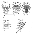
Anhand der Zeichnungen werden Ausführungsbeispiele der Erfindung näher
erläutert. Es zeigt:
Die in den Figuren 11 und 12 im montierten Zustand dargestellte
Schraubverbindungsanordnung dient zum Verbinden zweier plattenförmiger Bauteile
2, 4, welche nur von einer Seite her, in der Zeichnung nur von der Oberseite
her, zugänglich sind. Beispielsweise handelt es sich bei dem Bauteil 2 um das Karosserieblech
und bei dem Bauteil 4 um die Radhausschale für ein Kraftfahrzeug. Es
versteht sich jedoch, dass die Erfindung hierauf nicht beschränkt ist. The illustrated in Figures 11 and 12 in the assembled state
Screw connection arrangement is used for connecting two plate-
Die Schraubverbindungsanordnung besteht aus einer Schraube 6, die in Figur
1 als Einzelteil dargestellt ist, und einem mutterartigen Blindniet 8, der in den
Figuren 2 bis 6 als Einzelteil dargestellt ist.The screw connection arrangement consists of a
Wie in Figur 1 zu sehen ist, besteht die Schraube 6 in üblicher Weise aus
einem Schaft mit einem Gewinde 10 und einem Schraubenkopf 12, der mit einer
Schlüsselaufnahme 14 zum Drehen der Schraube versehen ist. Die Schraube 6 ist im
dargestellten Ausführungsbeispiel als selbstfurchende Schraube mit rechtsgängigem
Rundgewinde ausgebildet, die vorzugsweise aus einem hochfesten Kunststoff besteht,
wenngleich auch eine Schraube aus Stahl verwendet werden könnte.As can be seen in Figure 1, the
Der in den Figuren 2 bis 6 dargestellte mutterartige Blindniet 8 hat einen
hülsenförmigen Grundkörper 16, der an seinem einen axialen Ende mit einem
Flansch 18 versehen ist. Der Flansch 18 hat an seiner Unterseite eine Dichtlippe 19,
deren Funktion weiter unten erläutert wird.The illustrated in Figures 2 to 6 nut-like
Der Grundkörper 16 hat eine Aufnahmebohrung 20 zur Aufnahme der
Schraube 6. Die Aufnahmebohrung 20 besteht aus einem unteren Bohrungsabschnitt
22 kleineren Durchmessers und einem oberen Bohrungsabschnitt 24 größeren
Durchmessers, die durch eine Fase miteinander verbunden sind. Der Durchmesser
des Bohrungsabschnittes 22 ist hierbei so bemessen, dass die selbstfurchende
Schraube 6 beim Einschrauben in den Blindniet 8 in diesem Bereich ein Gewinde
formt. Stattdessen könnte jedoch der Blindniet 8 im Bereich des Bohrungsabschnittes
22 auch mit einem vorgeformten Gewinde zur Aufnahme des Gewindes 10 der
Schraube 6 versehen sein.The
Der Durchmesser des Bohrungsabschnittes 24 entspricht dem Außendurchmesser
des Gewindes 10 der Schraube 6, so dass die Schraube 6 ungehindert in den
Bohrungsabschnitt 24 eingeführt werden kann. Aufgrund des größeren Durchmessers
des Bohrungsabschnittes 24 ist die Wandstärke des Blindniets 8 in diesem Bereich
verringert, wobei die Wandstärke so gewählt wird, dass der Blindniet 8 in diesem
Bereich relativ leicht verformt werden kann, wie noch genauer erläutert wird.The diameter of the
Der Blindniet 8 ist an seiner Innenseite im Bereich des Bohrungsabschnittes
24 mit mehreren wendelförmig verlaufenden Stützrippen 25 versehen. (Fig. 3-6). Im
dargestellten Ausführungsbeispiel sind fünf Stützrippen vorgesehen, die linksgängig
und somit gegensinnig zum Gewinde 10 der Schraube 6 ausgebildet sind. Die Stützrippen
25 verlaufen von einem radial nach innen ragenden ringförmigen Vorsprung
27 am Flanschende des Grundkörpers 16 aus bis zum entgegengesetzten Ende des
Bohrungsabschnittes 24. Der Zweck der Stützrippen 25 wird weiter unten genauer
erläutert.The
Der Grundkörper 16 ist an seinem vom Flansch 18 abgewandten axialen
Ende von einem Boden 26 verschlossen, so dass das Innere der Aufnahmebohrung
20 an diesem Ende wasserdicht ist. Falls die Schraubverbindung nicht wasserdicht
sein muss, kann das betreffende Ende des Grundkörpers 16 auch offen bleiben, wie
dies bei der abgewandelten Ausführungsform des Blindniets 8' in Figur 7 der Fall
ist.The
Der Grundkörper 16 ist an seiner zylindrisch ausgebildeten Außenseite 28
mit einer Wendel 30 versehen. Die Wendel 30 hat im dargestellten Ausführungsbeispiel
vier Gänge 32, die schraubenförmig um die zylindrische Außenseite 28 des
Grundkörpers 16 über einen axialen Bereich entsprechend dem Bohrungsabschnitt
24 und einem Teil des Bohrungsabschnittes 22 verlaufen. Die Wendel 30 hat die
Form eines rechtsgängigen Spitzgewindes, d.h., dass die Gänge 32 der Wendel 30
in einem Axialschnitt (Figur 3) ein Dreieckprofil haben. Die Gänge 32 der Wendel
30 laufen an ihrem vom Flansch 18 abgewandten Ende in einer Fase 34 aus, was
das Einführen des Blindniets 8 in ein Befestigungsloch 36 des zugehörigen Bauteils
2 erleichtert.The
Wie in Figur 8 zu sehen ist, ist das Befestigungsloch 36 des Bauteils 2
quadratisch ausgebildet. Die Anzahl der Ecken des Befestigungsloches 36 ist somit
gleich der Anzahl der Gänge 32 der Wendel 30. Die Abmessungen des Befestigungsloches
36 und des Blindnietes 8 sind hierbei so gewählt, dass die Seitenlänge
des quadratischen Befestigungsloches 36 dem Durchmesser der zylindrischen Außenseite
28 des Grundkörpers 16 entspricht. Der Außendurchmesser der Wendel 30
ist geringfügig kleiner als der Abstand jeweils zweier diagonal gegenüberliegender
Ecken des mehreckigen Befestigungsloches 36. Das Profil des Spitzgewindes der
Wendel 30 ist hierbei so gewählt, dass es im montierten Zustand nahezu vollständig
die Ecken des quadratischen Befestigungsloches 36 ausfüllt. Der Steigungswinkel
der Wendel 30 ist größer als der Selbsthemmungswinkel; vorzugsweise liegt er im
Bereich von 50° bis 60°, insbesondere bei ca. 55°.As can be seen in FIG. 8, the
Wie insbesondere in den Figuren 4 und 6 zu sehen ist, gehen die Gänge 32
der Wendel 30 an ihren am Flansch 18 angrenzenden Ende in einen querschnittserweiterten
Körperabschnitt 35 über. Der querschnittserweiterte Körperabschnitt 35
wird einerseits durch eine radiale Vergrößerung der Wendelgänge 32 selbst und
andererseits durch zusätzliches Material zwischen den Wendelgängen gebildet, und
zwar derart, dass der Körperabschnitt 35 eine Außenfläche 37 hat, deren Querschnittsform
der Form des mehreckigen Befestigungsloches 36 entspricht. Im dargestellten
Ausführungsbeispiel hat daher der Körperabschnitt 35 angrenzend am
Flansch 18 (in der Schnittebene IV-IV, siehe Figuren 3, 4) einen praktisch quadratischen
Querschnitt, der im montierten Zustand im wesentlichen formschlüsig von
dem quadratischen Befestigungsloch 36 des Bauteils 2 aufgenommen wird, wie
noch genauer erläutert wird.As can be seen in particular in Figures 4 and 6, go the aisles 32nd
the
Der einstückig ausgebildete Blindniet 8 besteht zweckmäßigerweise ebenfalls
aus einem Kunststoff, so dass Schraube 6 und Blindniet 8 eine leicht recycelbare
Ganzkunststofflösung bilden. In Frage kommt ein schlagzähes Polyamid oder
ein anderer schlagzäher Kunststoff, ein elastomerer Kunststoff oder Gummi. Das
Material muss in jedem Fall so gewählt werden, dass es ausreichend elastisch verformbar
ist, um eine (noch zu beschreibende) Nietfaltung des Blindniets 8 zu ermöglichen
und andererseits für eine ausreichende Festigkeit der Verbindung der
beiden Bauteile 2, 4 zu sorgen.The integrally formed
Anhand der Figuren 9 bis 12 wird nun der Zusammenbau der beschriebenen
Verbindungsanordnung erläutert. Zum Verbinden des Blindniets 8 mit dem unteren
Bauteil 2 wird der Blindniet 8 zunächst in das quadratische Befestigungsloch 36 des
Bauteils 2 axial eingedrückt (siehe Figur 9). Hierbei dienen die Fasen 34 an den
Enden der Gänge 32 der Wendel 30 als Findehilfe. Beim axialen Eindrücken führt
der Blindniet 8 aufgrund der großen Steigung der viergängigen Wendel 30 eine
rechtsdrehende Bewegung aus, bis der Flansch 18 an der Oberseite des Bauteils 2
anliegt. Hierbei wird der am oberen Ende der Wendel 30 vorgesehene quadratische
Körperabschnitt 35 von dem quadratischen Befestigungsloch 36 des Bauteils 2 im
wesentlichen formschlüssig aufgenommen, so dass der Blindniet 8 im Bauteil 2
drehfest sitzt.With reference to the figures 9 to 12, the assembly of the described
Connection arrangement explained. For connecting the
Da die Innenflächen des quadratischen Befestigungsloches 36 nicht an den
schraubenförmigen Verlauf der Gänge 32 der Wendel 30 angepasst sind, kommt es
zu einer leichten Selbsthemmung zwischen der Wendel 30 und der Wandfläche des
Befestigungsloches 36, welche umso größer ist, je größer die Dicke des plattenförmigen
Bauteils 2 ist. Die Dicke des plattenförmigen Bauteils 2 kann beispielsweise
im Bereich von 0,8 bis 2,5 mm liegen, wobei an dieser Stelle zu erwähnen ist, dass
die Verbindungsanordnung nicht an eine spezielle Dicke der plattenförmigen Bauteile
angepasst werden muss, sondern für einen größeren Bereich unterschiedlicher
Dicken geeignet ist.Since the inner surfaces of the square mounting
Wie in den Figuren 2, 6 und 9 zu sehen ist, können zusätzliche Noppen 38
an der Außenseite 28 des Grundkörpers vorgesehen werden, die als weitere Verliersicherung,
insbesondere bei relativ kleiner Dicke des plattenförmigen Bauteils 2,
dienen.As can be seen in Figures 2, 6 and 9,
Es wird nun das obere Bauteil 4 auf den Flansch 18 des Blindniets 8 so aufgelegt,
dass ein Befestigungsloch 40 des Bauteils 4 zu der Aufnahmebohrung 20 des
Blindniets 8 fluchtet. Das Befestigungsloch 40 des Bauteils 4 ist kreisrund und hat
einen Durchmesser, der dem Außendurchmesser des Gewindes 10 der Schraube 6
entspricht. Die Schraube 6 kann daher problemlos durch das Befestigungsloch 40
hindurch in die Aufnahmebohrung 20 des Blindniets 8 eingeführt und mit dem
Blindniet 8 verschraubt werden. Wie bereits weiter oben erwähnt, formt hierbei das
Gewinde 10 der Schraube 6 ein entsprechendes Gewinde in der Wand des Grundkörpers
16 im Bereich des Bohrungsabschnittes 22.Now, the
Beim Einschrauben der Schraube 6 in den Blindniet 8 wird der untere Abschnitt
des Grundkörpers 16 (im Bereich des Bohrungsabschnittes 22) um einen
Hub H nach oben gegen die Unterseite des Bauteils 2 gezogen, siehe Fig. 11. Hierbei
falten sich der dünnwandige Abschnitt des Grundkörpers 16 und die Gänge 32
der Wendel 30 im Bereich des Bohrungsabschnittes 22 so, dass die entsprechenden
Flanken der Wendel 30 leicht rechtsdrehend verformt und gegen die Unterseite des
Bauteils 2 angedrückt werden. Es kommt somit zu einer partiellen Anlage zwischen
den betreffenden Flanken der Wendel 30 und dem Bauteil 2, wodurch die Schraubverbindung
zwischen den Bauteilen 2 und 4 erreicht ist.When screwing the
Um diese Faltung zu ermöglichen, wird die Wandstärke des Grundkörpers
16 im Bereich des Bohrungsabschnittes 24 entsprechend dünn gewählt. Der hierdurch
gebildete freie Zwischenraum zwischen dem Außenumfang des Gewindes 10
der Schraube 6 und der Innenwand des Bohrungsabschnittes 24 wird durch die
Stützrippen 25 überbrückt, deren Steigung gegensinnig (linksgängig) zu der Steigung
des Gewindes 10 der Schraube 6 ist. Da die Stützrippen 25 nicht axial, sondern
schräg zur Achsrichtung verlaufen, knicken sie bei dem Faltvorgang unbehindert
in Achsrichtung, wobei sie jedoch aufgrund ihrer Anlage am Außenumfang des
Gewindes 10 der Schraube 6 ein Ausweichen des Materials des Blindniets 6 radial
nach innen verhindern. Außerdem drücken sie die Außenwand des Körperabschnitts
35 am Ende der Wendel 30 in Anlage mit der Umfangsfläche des Befestigungsloches
36 des Bauteils 2.To allow this folding, the wall thickness of the body is
16 selected in the region of the
Der hierdurch erzielte Formschluss zwischen dem Körperabschnitt 35 und
dem Befestigungsloch 36 sorgt somit für eine Drehsicherung des Blindniets 8 bei
der Montage, und zwar sowohl beim Formen des Gewindes innerhalb des Bohrungsabschnittes
22 des Blindniets 8 wie auch bei dem Faltvorgang. Genauer gesagt,
kommt es bei diesen Montageschritten zu einer vollflächigen Anlage zwischen
den hälftigen Flächenabschnitten 37a der Außenfläche 37 des Körperabschnitts 35
und den entsprechenden Flächenabschnitten des Befestigungsloches 36 (siehe Fig.
4), wodurch das durch die rechtsdrehende Bewegung der Schraube 6 erzeugte
Drehmoment in ausreichender Flächenpressung aufgenommen wird. Da die zu den
Flächenabschnitten 37a benachbarten Flächenabschnitte 37b hierbei keine drehmomentübertragende
Funktion erfüllen, können sie, wie in Fig. 4 zu sehen ist, leicht
zurückversetzt ausgebildet werden, was der Herstellung des Blindniets mittels eines
Plattenwerkzeuges (nicht gezeigt) das Entformen aus der Spritzgießform erleichtert.The thus achieved positive connection between the
Der Schraub-und Faltvorgang kann durch Anlage der Schraube 6 am Boden
26 des Blindniets 8 beendet werden. Eine andere Möglichkeit besteht darin, das
Schraubmoment, mit dem die Schraube 6 in den Blindniet 8 eingeschraubt wird, zu
begrenzen, so dass der Schraubvorgang nach Anlage des Schraubenkopfes 12 am
Bauteil 4 durch Erreichen des Grenzmomentes beendet wird. Dies erlaubt es, die
beschriebene Verbindungsanordnung für plattenförmige Bauteile unterschiedlicher
Dicke einzusetzen.The screwing and folding process can be done by investing the
Im montierten Zustand wird die Dichtlippe 19 am Flansch 18 des Blindniets
8 gegen die Oberseite des Bauteils 2 angedrückt, wodurch eine Abdichtung zur
Umgebung erzielt wird. Da ferner das untere Ende des Blindniets 8 durch den Boden
26 verschlossen ist, ist die Verbindungsanordnung wasserdicht.In the assembled state, the sealing
Bei dem beschriebenen Ausführungsbeispiel ist die Wendel 30 viergängig
und das Befestigungsloch 36 viereckig ausgebildet. Es versteht sich jedoch, dass die
Anzahl der Gänge der Wendel 30 und die Anzahl der Ecken des Befestigungsloches
36 auch anders gewählt werden können; so sind Lösungen mit z.B. drei, fünf oder
sechs Wendelecken bzw. Ecken des Mehrecks denkbar. Ferner sind im beschriebenen
Ausführungsbeispiel das Gewinde 10 der Schraube 6 und die Wendel 30 des
Blindniets 8 rechtsgängig ausgebildet, während die Stützrippen 25 im Inneren des
Blindniets 8 linksgängig ausgebildet sind. Es versteht sich jedoch, dass die Anordnung
auch umgekehrt getroffen werden kann.In the described embodiment, the
Claims (22)
einer Schraube (6) und einem mutterartigen Blindniet (8), die in Befestigungslöcher (36, 40) der beiden Bauteile (2, 4) einsteckbar und zum Herstellen der Verbindung miteinander verschraubbar sind, wobei das Befestigungsloch (36) eines der Bauteile (2, 4) als Mehreck ausgebildet ist,
welcher Blindniet (8) aus einem elastisch verformbaren Material besteht und einen Grundkörper (16) aufweist, der mit einer Aufnahmebohrung (20) für das Gewinde (10) der Schraube (6) und an seiner Außenseite (28) mit einer mehrgängigen Wendel (30) versehen ist, deren Außendurchmesser dem Abstand jeweils zweier diagonal gegenüberliegender Ecken des mehreckigen Befestigungsloches (36) entspricht und deren Gängeanzahl gleich der Anzahl der Ecken des mehreckigen Befestigungsloches (36) ist,
so dass beim Einschrauben der Schraube (6) in die Aufnahmebohrung (20) des Blindniets (8) der Grundkörper (16) und die Wendel (30) gefaltet und dadurch die Gänge (32) der Wendel (30) mit einem Teil ihrer Flanken an das zugehörige Bauteil (2) angedrückt werden.Connecting arrangement for connecting two components (2, 4), with
a screw (6) and a nut-like blind rivet (8) which can be inserted into fastening holes (36, 40) of the two components (2, 4) and screwed together to make the connection, wherein the fastening hole (36) of one of the components (2 , 4) is designed as a polygon,
which blind rivet (8) consists of an elastically deformable material and has a base body (16) which is provided with a receiving bore (20) for the thread (10) of the screw (6) and on its outside (28) with a multi-turn helix (30 ) whose outer diameter corresponds to the distance between two diagonally opposite corners of the polygonal mounting hole (36) and whose passage number is equal to the number of corners of the polygonal mounting hole (36),
so that when screwing the screw (6) into the receiving bore (20) of the blind rivet (8) of the base body (16) and the coil (30) folded and thereby the passages (32) of the coil (30) with a part of their flanks the associated component (2) are pressed.
Applications Claiming Priority (2)
| Application Number | Priority Date | Filing Date | Title |
|---|---|---|---|
| DE20311263U DE20311263U1 (en) | 2003-07-22 | 2003-07-22 | Screw connection arrangement for connecting two components |
| DE20311263U | 2003-07-22 |
Publications (2)
| Publication Number | Publication Date |
|---|---|
| EP1500829A1 true EP1500829A1 (en) | 2005-01-26 |
| EP1500829B1 EP1500829B1 (en) | 2006-07-05 |
Family
ID=28051640
Family Applications (1)
| Application Number | Title | Priority Date | Filing Date |
|---|---|---|---|
| EP04009585A Expired - Lifetime EP1500829B1 (en) | 2003-07-22 | 2004-04-22 | Screw connecting arrangement for connecting two pieces |
Country Status (3)
| Country | Link |
|---|---|
| US (1) | US6926483B2 (en) |
| EP (1) | EP1500829B1 (en) |
| DE (2) | DE20311263U1 (en) |
Families Citing this family (21)
| Publication number | Priority date | Publication date | Assignee | Title |
|---|---|---|---|---|
| US20060103282A1 (en) * | 2003-03-12 | 2006-05-18 | Avendano Jose G | Fastening system for appliance cabinet assembly |
| DE10329826A1 (en) * | 2003-06-27 | 2005-01-13 | Festool Gmbh | sanding pad |
| DE102004003240A1 (en) * | 2004-01-21 | 2005-08-11 | Newfrey Llc, Newark | blind rivet nut |
| DE102004021484B4 (en) * | 2004-04-30 | 2018-11-29 | Böllhoff Verbindungstechnik GmbH | Method for producing a connection arrangement |
| DE102006023320A1 (en) * | 2006-05-18 | 2007-11-22 | Fischerwerke Artur Fischer Gmbh & Co. Kg | Schraubblindniet, connection arrangement with the Schraubblindniet and method for connecting to the Schraubblindniet |
| US7854324B2 (en) * | 2006-08-14 | 2010-12-21 | C & D Enterprises, Inc. | Shipping carrier |
| DE102008039819B4 (en) * | 2008-08-22 | 2011-04-07 | Takata-Petri Ag | Clamping element and arrangement with a clamping element |
| GB2463043B (en) * | 2008-08-29 | 2013-01-30 | Avdel Uk Ltd | Blind fastener |
| US8591559B2 (en) * | 2008-10-27 | 2013-11-26 | The University Of Toledo | Fixation assembly having an expandable insert |
| US20100217309A1 (en) * | 2009-02-20 | 2010-08-26 | Boston Scientific Scimed, Inc. | Plug for arteriotomy closure and method of use |
| DE102010008457A1 (en) * | 2010-02-18 | 2011-09-08 | A. Raymond Et Cie | Spannniet |
| US20130011217A1 (en) * | 2011-07-08 | 2013-01-10 | Guy Avellon | Rivet With Improved Contact Surface |
| CN105637670A (en) * | 2013-10-16 | 2016-06-01 | 台湾立凯绿能移动股份有限公司 | Locking state confirmation means of battery contact special for electric vehicle |
| CN105626657B (en) * | 2014-10-28 | 2018-09-11 | 上海汽车集团股份有限公司 | Riveting nut |
| US9869336B2 (en) | 2015-01-26 | 2018-01-16 | Good Earth Lighting, Inc. | Anchor fastener |
| US10539171B2 (en) | 2015-01-26 | 2020-01-21 | Good Earth Lighting, Inc. | Anchor fastener |
| DE102015009044A1 (en) * | 2015-07-13 | 2017-01-19 | Sfs Intec Holding Ag | Process for the preparation of a compound |
| DE102015113676A1 (en) * | 2015-08-18 | 2017-02-23 | Profil Verbindungstechnik Gmbh & Co. Kg | Blindnietelement |
| FR3063121B1 (en) * | 2017-02-22 | 2019-03-29 | Bollhoff Otalu S.A. | CRYSTAL INSERT, ELEMENT AND FIXING ASSEMBLY COMPRISING SUCH AN INSERT AND METHODS OF MANUFACTURING SUCH PIECES. |
| DE102020110872A1 (en) | 2020-04-22 | 2021-10-28 | Bayerische Motoren Werke Aktiengesellschaft | Rivet element for setting a thread |
| GB2600414A (en) * | 2020-10-27 | 2022-05-04 | Airbus Operations Ltd | Blind fasteners |
Citations (6)
| Publication number | Priority date | Publication date | Assignee | Title |
|---|---|---|---|---|
| FR1406174A (en) * | 1963-07-25 | 1965-07-16 | Firth Cleveland Fastenings Ltd | Screw fixing device |
| DE2818588A1 (en) * | 1977-06-08 | 1978-12-14 | Vyzk Ustav Mech | THREADED INSERT FOR ONE-SIDED FASTENING IN PREFERABLY THIN SHEETS |
| US4182216A (en) * | 1978-03-02 | 1980-01-08 | Textron, Inc. | Collapsible threaded insert device for plastic workpieces |
| DE3612478A1 (en) * | 1986-04-14 | 1987-10-15 | Tucker Gmbh | METAL BLIND RIVET |
| DE9310735U1 (en) * | 1993-07-13 | 1993-09-16 | Gesellschaft für Befestigungstechnik Gebr. Titgemeyer GmbH & Co. KG, 49084 Osnabrück | Blind rivet nut |
| DE20112171U1 (en) | 2001-07-23 | 2001-10-11 | Böllhoff GmbH, 33649 Bielefeld | Screw blind rivet connection arrangement |
Family Cites Families (13)
| Publication number | Priority date | Publication date | Assignee | Title |
|---|---|---|---|---|
| US1036825A (en) * | 1911-05-01 | 1912-08-27 | Louis Antoine Garchey | Nut-lock. |
| US2075411A (en) * | 1934-07-21 | 1937-03-30 | Groov Pin Corp | Fastener stud |
| US2918841A (en) * | 1956-11-01 | 1959-12-29 | Illinois Tool Works | Blind fastener formed of plastic and containing longitudinal slots which permit rosette type of distortion of shank |
| US3283641A (en) * | 1964-06-04 | 1966-11-08 | John B Wagner | Soft screw anchor |
| DK125488B (en) * | 1969-05-30 | 1973-02-26 | L Mortensen | Tubular expansion dowel body or similar fastener and method of making the same. |
| DE2917611C2 (en) * | 1979-05-02 | 1983-09-29 | Hilti AG, 9494 Schaan | Dowel and tool for making a hole for the dowel |
| DE3640312A1 (en) | 1986-11-26 | 1988-06-09 | Tox Duebel Werk | SPREADING DOWEL |
| US4776737A (en) * | 1986-12-23 | 1988-10-11 | Phillips Plastics Corporation | Re-usable two-piece blind fastener |
| GB2211261B (en) * | 1987-10-19 | 1991-03-27 | Nifco Inc | Coupler for coupling together plates |
| JPH0755374Y2 (en) * | 1989-09-12 | 1995-12-20 | 株式会社ニフコ | Screw rivet |
| FR2682725B1 (en) | 1991-10-16 | 1995-02-24 | Prospection & Inventions | ANKLE FOR FIXING A PART TO A LOW THICKNESS SUPPORT WALL. |
| US5636953A (en) * | 1996-06-11 | 1997-06-10 | Trw Inc. | Roof rail attachment assembly |
| US6254325B1 (en) * | 2000-01-28 | 2001-07-03 | Steve Kun | Anchor assembly for a wall, floor or like supporting structure |
-
2003
- 2003-07-22 DE DE20311263U patent/DE20311263U1/en not_active Expired - Lifetime
-
2004
- 2004-04-22 DE DE502004000906T patent/DE502004000906D1/en not_active Expired - Fee Related
- 2004-04-22 EP EP04009585A patent/EP1500829B1/en not_active Expired - Lifetime
- 2004-07-09 US US10/887,959 patent/US6926483B2/en not_active Expired - Fee Related
Patent Citations (6)
| Publication number | Priority date | Publication date | Assignee | Title |
|---|---|---|---|---|
| FR1406174A (en) * | 1963-07-25 | 1965-07-16 | Firth Cleveland Fastenings Ltd | Screw fixing device |
| DE2818588A1 (en) * | 1977-06-08 | 1978-12-14 | Vyzk Ustav Mech | THREADED INSERT FOR ONE-SIDED FASTENING IN PREFERABLY THIN SHEETS |
| US4182216A (en) * | 1978-03-02 | 1980-01-08 | Textron, Inc. | Collapsible threaded insert device for plastic workpieces |
| DE3612478A1 (en) * | 1986-04-14 | 1987-10-15 | Tucker Gmbh | METAL BLIND RIVET |
| DE9310735U1 (en) * | 1993-07-13 | 1993-09-16 | Gesellschaft für Befestigungstechnik Gebr. Titgemeyer GmbH & Co. KG, 49084 Osnabrück | Blind rivet nut |
| DE20112171U1 (en) | 2001-07-23 | 2001-10-11 | Böllhoff GmbH, 33649 Bielefeld | Screw blind rivet connection arrangement |
Also Published As
| Publication number | Publication date |
|---|---|
| EP1500829B1 (en) | 2006-07-05 |
| US6926483B2 (en) | 2005-08-09 |
| US20050019129A1 (en) | 2005-01-27 |
| DE20311263U1 (en) | 2003-09-11 |
| DE502004000906D1 (en) | 2006-08-17 |
Similar Documents
| Publication | Publication Date | Title |
|---|---|---|
| EP1500829B1 (en) | Screw connecting arrangement for connecting two pieces | |
| EP0662200B1 (en) | Device for joining at least two elements | |
| EP1710454B1 (en) | Blind rivet | |
| DE4332494A1 (en) | Threaded bolt arrangement with sliding bush | |
| DE202004012733U1 (en) | Adjustment unit for setting the distance between two components | |
| EP0206327B1 (en) | Device for linking tubes | |
| WO2019137722A1 (en) | Blind rivet | |
| DE3232926A1 (en) | Device for connecting structural parts or structural elements to one another | |
| DE10133063B4 (en) | Fastening device and fastening element | |
| DE2211496A1 (en) | Sealing connection between two cylindrical workpieces | |
| DE1500792A1 (en) | Threaded fastening arrangement | |
| DE10334898B4 (en) | Retaining element for fixing at least one bearing | |
| DE4231320A1 (en) | Detachable pin socket connection between two parts - has interengaging convex and concave wedge sections on cams and grooves to ensure reliable locking engagement. | |
| DE3703024A1 (en) | CONNECTING DEVICE WITH A PLASTIC SPREADING NUT | |
| DE102007042034A1 (en) | Fixing system for fastening components, in particular for motor vehicles | |
| DE10253448A1 (en) | Thread insert for plastic component has deep drawn thread tube with bulged end and shoulder to engage panel to be attached | |
| DE3540413C2 (en) | Fastening screw | |
| EP1528011A1 (en) | Coaxial two component cartridge | |
| DE102005006592A1 (en) | Process for the primary molding of a molded part and molded part produced by primary molding, in particular nut | |
| AT400977B (en) | PIPE FASTENING ARRANGEMENT | |
| EP2265831B1 (en) | Screw portion for fastening a rim of a motor vehicle | |
| DE102023131872A1 (en) | Stackable closure element for closing openings in support components | |
| DE202007013321U1 (en) | Extrusion blow molded component made of thermoplastic material | |
| EP0738835B1 (en) | Dowel with screen-type sleeve | |
| DE102022100210A1 (en) | Two-part union nut |
Legal Events
| Date | Code | Title | Description |
|---|---|---|---|
| PUAI | Public reference made under article 153(3) epc to a published international application that has entered the european phase |
Free format text: ORIGINAL CODE: 0009012 |
|
| AK | Designated contracting states |
Kind code of ref document: A1 Designated state(s): AT BE BG CH CY CZ DE DK EE ES FI FR GB GR HU IE IT LI LU MC NL PL PT RO SE SI SK TR |
|
| AX | Request for extension of the european patent |
Extension state: AL HR LT LV MK |
|
| 17P | Request for examination filed |
Effective date: 20050420 |
|
| 17Q | First examination report despatched |
Effective date: 20050705 |
|
| AKX | Designation fees paid |
Designated state(s): DE FR GB |
|
| GRAP | Despatch of communication of intention to grant a patent |
Free format text: ORIGINAL CODE: EPIDOSNIGR1 |
|
| GRAS | Grant fee paid |
Free format text: ORIGINAL CODE: EPIDOSNIGR3 |
|
| GRAA | (expected) grant |
Free format text: ORIGINAL CODE: 0009210 |
|
| AK | Designated contracting states |
Kind code of ref document: B1 Designated state(s): DE FR GB |
|
| REG | Reference to a national code |
Ref country code: GB Ref legal event code: FG4D Free format text: NOT ENGLISH |
|
| REF | Corresponds to: |
Ref document number: 502004000906 Country of ref document: DE Date of ref document: 20060817 Kind code of ref document: P |
|
| GBT | Gb: translation of ep patent filed (gb section 77(6)(a)/1977) |
Effective date: 20061010 |
|
| ET | Fr: translation filed | ||
| PLBE | No opposition filed within time limit |
Free format text: ORIGINAL CODE: 0009261 |
|
| STAA | Information on the status of an ep patent application or granted ep patent |
Free format text: STATUS: NO OPPOSITION FILED WITHIN TIME LIMIT |
|
| 26N | No opposition filed |
Effective date: 20070410 |
|
| PGFP | Annual fee paid to national office [announced via postgrant information from national office to epo] |
Ref country code: DE Payment date: 20080624 Year of fee payment: 5 |
|
| PGFP | Annual fee paid to national office [announced via postgrant information from national office to epo] |
Ref country code: GB Payment date: 20080423 Year of fee payment: 5 |
|
| GBPC | Gb: european patent ceased through non-payment of renewal fee |
Effective date: 20090422 |
|
| REG | Reference to a national code |
Ref country code: FR Ref legal event code: ST Effective date: 20091231 |
|
| PG25 | Lapsed in a contracting state [announced via postgrant information from national office to epo] |
Ref country code: DE Free format text: LAPSE BECAUSE OF NON-PAYMENT OF DUE FEES Effective date: 20091103 |
|
| PG25 | Lapsed in a contracting state [announced via postgrant information from national office to epo] |
Ref country code: GB Free format text: LAPSE BECAUSE OF NON-PAYMENT OF DUE FEES Effective date: 20090422 Ref country code: FR Free format text: LAPSE BECAUSE OF NON-PAYMENT OF DUE FEES Effective date: 20091222 |
|
| PGFP | Annual fee paid to national office [announced via postgrant information from national office to epo] |
Ref country code: FR Payment date: 20080428 Year of fee payment: 5 |