EP0809339B1 - Elektrisches Installationsgerät - Google Patents
Elektrisches Installationsgerät Download PDFInfo
- Publication number
- EP0809339B1 EP0809339B1 EP97890080A EP97890080A EP0809339B1 EP 0809339 B1 EP0809339 B1 EP 0809339B1 EP 97890080 A EP97890080 A EP 97890080A EP 97890080 A EP97890080 A EP 97890080A EP 0809339 B1 EP0809339 B1 EP 0809339B1
- Authority
- EP
- European Patent Office
- Prior art keywords
- fixing body
- installation device
- recess
- electrical installation
- groove
- Prior art date
- Legal status (The legal status is an assumption and is not a legal conclusion. Google has not performed a legal analysis and makes no representation as to the accuracy of the status listed.)
- Expired - Lifetime
Links
- 238000010616 electrical installation Methods 0.000 title claims description 18
- 238000009434 installation Methods 0.000 claims description 61
- 239000000463 material Substances 0.000 claims description 9
- 238000006073 displacement reaction Methods 0.000 claims description 6
- 239000002184 metal Substances 0.000 claims description 5
- 239000012777 electrically insulating material Substances 0.000 claims description 2
- 230000000284 resting effect Effects 0.000 claims 2
- 230000000717 retained effect Effects 0.000 claims 1
- 210000000078 claw Anatomy 0.000 description 21
- 230000008719 thickening Effects 0.000 description 8
- 230000002349 favourable effect Effects 0.000 description 2
- 210000004013 groin Anatomy 0.000 description 2
- 239000012791 sliding layer Substances 0.000 description 2
- DHKHKXVYLBGOIT-UHFFFAOYSA-N 1,1-Diethoxyethane Chemical compound CCOC(C)OCC DHKHKXVYLBGOIT-UHFFFAOYSA-N 0.000 description 1
- 239000011354 acetal resin Substances 0.000 description 1
- 230000005540 biological transmission Effects 0.000 description 1
- 230000015572 biosynthetic process Effects 0.000 description 1
- 239000000919 ceramic Substances 0.000 description 1
- 229910010293 ceramic material Inorganic materials 0.000 description 1
- 238000010276 construction Methods 0.000 description 1
- 238000011161 development Methods 0.000 description 1
- 230000018109 developmental process Effects 0.000 description 1
- 239000002783 friction material Substances 0.000 description 1
- 239000010410 layer Substances 0.000 description 1
- 229920006324 polyoxymethylene Polymers 0.000 description 1
- 230000007704 transition Effects 0.000 description 1
Images

Classifications
-
- H—ELECTRICITY
- H02—GENERATION; CONVERSION OR DISTRIBUTION OF ELECTRIC POWER
- H02G—INSTALLATION OF ELECTRIC CABLES OR LINES, OR OF COMBINED OPTICAL AND ELECTRIC CABLES OR LINES
- H02G3/00—Installations of electric cables or lines or protective tubing therefor in or on buildings, equivalent structures or vehicles
- H02G3/02—Details
- H02G3/08—Distribution boxes; Connection or junction boxes
- H02G3/18—Distribution boxes; Connection or junction boxes providing line outlets
Definitions
- the invention relates to an electrical installation device according to the introductory part of claim 1.
- An installation device is known from DE 18 39 475 U, at which is provided a fixing body with a wedge surface, which an inclined edge of a base body slides.
- a Clamping screw serves as an adjustment element around the fixing body to press outwards along the sloping surface of the rim, if the clamping screw is screwed into the fixing body.
- This Construction has the disadvantage that the clamping screw inevitably inclined when screwing in, which means that it is in the Threaded hole in the fixation body can rub and only more difficult is detachable if the fixing body is to be reset. In front but everything is then also the fixing body with the screw slanted so that it is no longer on the sloping edge can slide with its wedge surface, but with an edge will "eat” firmly on the edge.
- DE 21 40 397 A shows an installation device with two am Molded base, i.e. with it one-piece spreading levers that by means of a wedge body adjustable via an adjusting screw or by a set screw pressing radially on a wedge surface are pivotable outward, the pivot point of the pivoting movement through a film hinge or through the transition of the spreading lever is set to the base. There, however, it can easily be used Tearing or breaking come.
- DE 43 24 633 A is finally an electrical installation device known as the starting point for the invention is to be seen, and in which the fixing body by along arcuate guides on the base body sliding expansion elements are formed.
- the spreading elements each have one upper bridge-like web, in which one on the support ring of the Base body with the help of a separate, movable in the support ring mounted swivel holding screw as Adjusting element engages.
- the fixation bodies are thus here each time the retaining screw is screwed into the passage according to an arcuate path in the radially outer operating position transferred.
- the invention provides an electrical solution to this problem Installation device with the features specified in claim 1 in front.
- Advantageous embodiments and further developments are the subject of the subclaims.
- Training becomes more advantageous to the above objective
- an exact movement of the respective fixing body when fixing the installation device in an installation box is ensured by the Fixing body in the corresponding recess in the base body straight essentially radially outwards, ie in the direction of the center axis of the base body towards the can wall, shifted becomes.
- the fixation body can be on its radially outer end face or outside be provided with claw elements or the like, with which he had a firm hold on when moving away Ensures the inner surface of the installation box.
- claw elements can on the fixing body, based on the axial direction of the installation device, are available in different depth positions, the fixing body itself at least on its radial Outside can have a relatively large axial dimension, so that the fixing body also in the area of cable through openings in the installation box with claw elements on the box wall, namely in particular between these openings and the one installed Condition with the wall in which the installation box is inserted is the final front of the installation box (Or facing away from the front axially behind it Openings) can engage.
- the pin-like adjusting element is rotatably arranged on the base body and the fixing body is one to the direction of its displacement has an oblique wedge surface, which when turning axially adjustable adjusting element with respect to the base body the wedge surface of the fixing body rests, a simple outward displacement of the fixing body with a comparatively small Torque on the adjustment element and reliable self-locking reached with the fixing body pushed out.
- the adjustment element thus enters here in a manner known per se Screw thread with which it is axial with respect to the base body is adjustable, and the fixing body forms a kind of wedge whose inclined wedge surface abuts the adjustment element and in In the event of an adjustment, a force is exerted over this wedge surface is broken down into components, one of which is radial Moving the fixation body is used. Against however, an undesired pushing back of the fixing body acts the system wedge-surface adjustment element-thread self-locking, see above that the fixing body with sufficient force against the inner surface the installation box can be pushed to an unwanted Pull the installation device out of the box prevent.
- the im Fixing body provided groove-like recess the wedge surface forms and has undercut trained side walls, the geometric axis of this recess in the Movability of the fixing body corresponding radial plane lies and at an angle to the geometric axis of the sliding bearing of the fixing body, and that the pin-like adjusting element one in the groove-like recess of the fixing body has thickening located in the axial direction of the Adjustment element in the groove-like recess held and in the axial direction of the groove-like recess this reces is displaceable.
- the pitch angle of the wedge surface (relative to the direction of the sliding movement) favorable;
- the self-locking described would be the Wedge angle of the wedge, based on the direction of the displacement movement of the fixing body to choose comparatively small.
- the inclined position of the wedge surface geometric axis of the sliding bearing of the fixing body is between 20 ° and 45 °, it being particularly preferred that the inclination is about 30 °.
- the fixing body can be made of metal, the has claws on the outside. But since the present Installation device the respective fixation body compared to an installation device with the known expanding claws within the base body extends relatively far radially inwards, whereby he get close to electrical connectors can, it has also proven to be advantageous for security reasons proven if the fixing body made of electrically insulating Material exists.
- the fixing body can be made of, for example Plastic or ceramic exist, whereas the base body of the Installation device, for example, from an acetal resin can exist. With such materials is also a good one Slidability of the fixing body ensured in the base body. In itself, it can also be cheap, especially one low-friction sliding lining in the recess of the base body and / or on the underside of the fixing body, in the area of sliding surfaces.
- the fixing body can on its radial outside (End face), for example, with strip-shaped claw elements be provided; preferably he wears one on the outside or several points or spikes.
- These spikes or spikes could be formed from the material of the fixing body, wherein then, however, it is necessary that the material of the Fixing body has sufficient hardness.
- Such Formation of spikes, groins or thorns immediately easy from the material of the fixing body would be conceivable above all if there is corrugation on the inside surface of the installation box or the like is provided, as is known per se; it would then be a kind of positive engagement of the inner surface of the can and the fixing body.
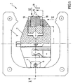
- a base body in a conventional manner 2 provided, in the present example for the implementation a Schuko socket is designed and also in itself conventionally connected to a frame 3, the Front 3 'of the installation device 1 in the installed state (see Fig. 2).
- the frame 3 is with after rear angled tabs 4 on the base body 2, namely its front, fastened with the aid of rivet sleeves 5, and these rivet sleeves 5 are provided with an internal thread, wherein each a pin-like adjusting element 6, which has a shaft section 7 with a corresponding external thread, in this threaded rivet sleeve 5 is screwed.
- the base body 2 In the base body 2 is, in the axial direction seen electrical installation device 1, cf. also the axis 8 in FIG. 2, behind the rivet sleeves 5 in each case a recess 9 provided, in which a fixing body 10 is slidably received is.
- This fixing body 10 is designed like a slide and adjustable in translation, with its interior or Underside on the bottom 11 of the recess 9 slides.
- the fixation body 10 is, as well as from FIG. 2, in particular also from FIG. 3 can be seen, formed overall in the manner of a wedge, the front 3 'of the installation device 1 facing top has a wedge surface 12 which with the pin-like adjustment element 6, with its inside Front side, which is a general in the present example has lenticular thickening 13 cooperates.
- the or each fixing body 10 On its radially outer end, hereinafter briefly the outside called, the or each fixing body 10 carries a claw element, with which he is in the operating position, cf. Fig. 2, right Half, pressed against the inner surface 14 of an installation box 15 is provided for receiving the installation device 1 is.
- this is Claw element formed by mandrels 16, preferably each two such mandrels 16 side by side on the outside of the Fixing body 10 are provided (as shown in Fig.1, in of these mandrels 16 drawn in for illustration were, even if they correspond to the cut I-I in Fig. 2 would not be visible).
- the mandrels 16 are through the tips of embedded in the material of the fixing body 10 Metal pins 17 formed.
- the material of each Fixing body 10 is preferably an insulating plastic or Ceramic material, but possibly also metal.
- each fixing body 10 lateral in its bottom area Guide flanges 18, 19 with which he is in corresponding lateral recesses 20, 21 of the recess 9 in the base body 2 (see also Fig. 4 and 5) is performed.
- the fixing body 10 On the top of the wedge surface the fixing body 10 has a groove-like recess 22 on, whose side walls are undercut so that a wider guide "chamber" 23 below or within a inner guide slot 24 is obtained, the bottom 12 ' forms the aforementioned wedge surface 12.
- This wedge surface 12 runs at an angle ⁇ (see Fig. 7) relative to the geometric Axis 25 (see Fig. 2, left half) of the sliding bearing of the fixing body 10 in the recess 9, namely from increasing radially outwards inside, this wedge angle ⁇ , for example 30 °, generally between 20 ° and 45 °.
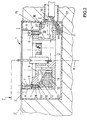
- the lenticular thickening 13 is, as in particular can be seen from Figure 4, over a smaller cross-section Shank section 28 with the threaded section 7 of the adjusting element 6, which carries the external thread.
- each fixing body 10 is made of its own inner rest position shown in Fig. 2 left half outwards against the inner surface 14 of the installation box 15 moved that the pin-like adjusting element 6 with the help a suitable tool, such as a screwdriver or an Allen key, depending on the head design of the adjustment element 6, rotated and screwed inward in the sleeve 5 will, i.e. is adjusted axially inward, the front end of the adjusting element 6 with the lenticular thickening 13 pressed against the wedge surface 12 of the groove-like recess 22 becomes.
- a suitable tool such as a screwdriver or an Allen key
- the fixing body has 10 'on its outside essentially over its entire height a toothing 31. Furthermore, the fixing body 10 'is on its oblique wedge surface 12 with a support 32 made of hard, provided with low-friction material.
- FIG. 7 but also that according to FIG. 5 and 6 are particularly suitable for working with installation boxes 15 with a corrugation 35 (see Fig. 7) on the inner surface 14 in order to fix the To achieve installation device 1 in the installation box 15.
- the mandrels 16 allow in the position shown a secure hold in the installation box 15 even if in this box 15 openings 36 for carrying electrical Feed lines or cables 37 are present: As from FIG. 2 can be seen, it is possible to use the mandrels 16 in such a way Provide height on the radial outside of the fixing body 10, that they are in the area between the opening 36 and the front 3 ' of the installation device 1 to the inner surface 14 of the installation box 15 are pressed (what with the conventional claws not possible).
- the radial outside of the fixing body 10 or 10 ' is in the exemplary embodiments shown, cf. e.g. Fig. 1 to 3. But it can also - especially in the embodiment according to Fig.5 / 6 or that according to Fig.7 - also be expedient, this radial To adjust the outside of the curvature of the installation box 15; if necessary, it is also sufficient to just the area of the prong bar 29 or the toothing 31 run correspondingly in an arc allow; in the case of three (or more) thorns 16 in one Height can also have their tips on a circular arc correspond to the radius of the can wall.
Landscapes
- Engineering & Computer Science (AREA)
- Architecture (AREA)
- Civil Engineering (AREA)
- Structural Engineering (AREA)
- Connection Of Plates (AREA)
Description
Claims (9)
- Elektrisches Installationsgerät (1) mit einem Sockelkörper (2) und wenigstens einem an diesem beweglich angeordneten Fixierkörper (10), welcher zum Festhalten des Installationsgerätes (1) in einer Installationsdose (15) vorgesehen und mit Hilfe eines Verstellelements (6) aus einer inneren Ruhestellung in einer im Sockelkörper (2) vorgesehenen Ausnehmung (9) im wesentlichen radial nach außen in eine Betriebsstellung zwangsläufig bewegbar und dabei mit seiner Außenseite an die Innenfläche der Installationsdose (15) anpressbar ist, und der aus dieser Betriebsstellung wieder nach innen in die Ruhestellung bewegbar und so von der Innenfläche der Installationsdose (15) lösbar ist, dadurch gekennzeichnet, dass der schieberartige Fixierkörper (10) in der Ausnehmung (9) geradlinig geführt ist, und dass der Fixierkörper (10) eine zur Richtung seiner Verschiebung schräg verlaufende Keilfläche (12) hat, wobei das am Sockelkörper (2) drehbar angeordnete, beim Drehen bezüglich des Sockelkörpers (2) axial verstellbare Verstellelement (6) an der Keilfläche (12) des Fixierkörpers (10) anliegt, dass der Fixierkörper (10) mit einer nutartigen Ausnehmung (22) versehen ist, in welche das stiftartige Verstellelement (6) ragt,dass die im Fixierkörper (10) vorgesehene nutartige Ausnehmung (22), die die Keilfläche (12) bildet, hinterschnitten ausgebildete Seitenwände aufweist, wobei die geometrische Achse (22') dieser Ausnehmung (22) in der der Verschiebbarkeit des Fixierkörpers (10) entsprechenden Radialebene (R) liegt und schräg zur geometrischen Achse (25) der Verschiebung des Fixierkörpers (10) verläuft, und dass das stiftartige Verstellelement (6) eine in der nutartigen Ausnehmung (22) des Fixierkörpers (10) befindliche Verdickung (13) aufweist, welche durch die hinterschnittenen Seitenwände in Axialrichtung des Verstellelements (6) formschlüssig in der nutartigen Ausnehmung (22) gehalten und in Axialrichtung der nutartigen Ausnehmung (22) in dieser Ausnehmung (22) verschiebbar ist.
- Elektrisches Installationsgerät nach Anspruch 1, dadurch gekennzeichnet, dass das Verstellelement (6) mit einer Wand der nutartigen Ausnehmung (22) in formschlüssigem Eingriff steht.
- Elektrisches Installationsgerät nach Anspruch 1 oder 2, dadurch gekennzeichnet, dass die Schrägstellung der Keilfläche (12) zur geometrischen Achse (25) der Verschiebelagerung des Fixierkörpers (10) zwischen 20° und 45° liegt.
- Elektrisches Installationsgerät nach Anspruch 3, dadurch gekennzeichnet, dass die Schrägstellung etwa 30° beträgt.
- Elektrisches Installationsgerät nach einem der Ansprüche 1 bis 4, dadurch gekennzeichnet, dass der Fixierkörper (10) aus elektrisch isolierendem Material besteht.
- Elektrisches Installationsgerät nach einem der Ansprüche 1 bis 5, dadurch gekennzeichnet, dass der Fixierkörper (10) an seiner Außenseite einen oder mehrere Zacken (29; 31) oder Dorne (16) trägt.
- Elektrisches Installationsgerät nach einem der Ansprüche 1 bis 6, dadurch gekennzeichnet, dass in das Material des Fixierkörpers (10) an der Außenseite wenigstens ein Metallstift (17), welcher einen Dorn (16) bildet, eingebettet ist.
- Elektrisches Installationsgerät nach Anspruch 6 oder 7, dadurch gekennzeichnet, dass der oder die an der Außenseite des Fixierkörpers (10) vorgesehenen Zacken oder Dorne (16) in der näher zur Vorderseite (3') des Installationsgerätes (1) liegenden Zone der Fixierkörper-Außenseite angeordnet ist bzw. sind.
- Elektrisches Installationsgerät nach einem der Ansprüche 1 bis 8, dadurch gekennzeichnet, dass der den Fixierkörper (10) führende Boden der im Sockelkörper (2) vorgesehenen Ausnehmung (9) ebenso wie die diesem Boden zugewandte Unterseite des Fixierkörpers (10) bezüglich einer zur Vorderseite (3') des Installationsgerätes (1) parallelen Ebene einwärts schräg abfallend verläuft.
Applications Claiming Priority (3)
| Application Number | Priority Date | Filing Date | Title |
|---|---|---|---|
| AT89796 | 1996-05-21 | ||
| AT897/96 | 1996-05-21 | ||
| AT0089796A AT403637B (de) | 1996-05-21 | 1996-05-21 | Elektrisches installationsgerät |
Publications (2)
| Publication Number | Publication Date |
|---|---|
| EP0809339A1 EP0809339A1 (de) | 1997-11-26 |
| EP0809339B1 true EP0809339B1 (de) | 2001-10-24 |
Family
ID=3502349
Family Applications (1)
| Application Number | Title | Priority Date | Filing Date |
|---|---|---|---|
| EP97890080A Expired - Lifetime EP0809339B1 (de) | 1996-05-21 | 1997-04-30 | Elektrisches Installationsgerät |
Country Status (4)
| Country | Link |
|---|---|
| EP (1) | EP0809339B1 (de) |
| AT (1) | AT403637B (de) |
| DE (1) | DE59705031D1 (de) |
| HU (1) | HU215425B (de) |
Families Citing this family (1)
| Publication number | Priority date | Publication date | Assignee | Title |
|---|---|---|---|---|
| DE102009050526A1 (de) * | 2009-10-23 | 2011-04-28 | Abb Ag | Unterputz-Elektro-Installationsgerät mit Spreizen |
Citations (1)
| Publication number | Priority date | Publication date | Assignee | Title |
|---|---|---|---|---|
| DE4324633A1 (de) * | 1993-07-22 | 1995-01-26 | Abb Patent Gmbh | Elektrisches Installationsgerät |
Family Cites Families (6)
| Publication number | Priority date | Publication date | Assignee | Title |
|---|---|---|---|---|
| DE1839475U (de) * | 1961-06-05 | 1961-10-19 | Fritz Keune | Elektroinstallationsgeraet fuer unterputzverlegung bzw. unterputz-schalter oder -steckdose. |
| DE2140397A1 (de) * | 1971-08-12 | 1973-02-15 | Bbc Brown Boveri & Cie | Elektrisches unterputz-installationsgeraet |
| US4071158A (en) * | 1975-08-11 | 1978-01-31 | Maheu Joseph S | Screw fastening device |
| GB2170660B (en) * | 1985-02-05 | 1988-10-12 | City Electrical Factors Ltd | Wall box for an electrical device |
| JPH01270709A (ja) * | 1988-04-23 | 1989-10-30 | Matsushita Electric Works Ltd | 床配線装置 |
| DE3941613A1 (de) * | 1988-12-20 | 1990-06-21 | May & Steffens Gmbh & Co Kg | Befestigungsvorrichtung |
-
1996
- 1996-05-21 AT AT0089796A patent/AT403637B/de not_active IP Right Cessation
-
1997
- 1997-04-30 EP EP97890080A patent/EP0809339B1/de not_active Expired - Lifetime
- 1997-04-30 DE DE59705031T patent/DE59705031D1/de not_active Expired - Fee Related
- 1997-05-05 HU HU9700844A patent/HU215425B/hu not_active IP Right Cessation
Patent Citations (1)
| Publication number | Priority date | Publication date | Assignee | Title |
|---|---|---|---|---|
| DE4324633A1 (de) * | 1993-07-22 | 1995-01-26 | Abb Patent Gmbh | Elektrisches Installationsgerät |
Also Published As
| Publication number | Publication date |
|---|---|
| ATA89796A (de) | 1997-08-15 |
| HUP9700844A3 (en) | 1998-05-28 |
| HU9700844D0 (en) | 1997-06-30 |
| HU215425B (hu) | 1998-12-28 |
| EP0809339A1 (de) | 1997-11-26 |
| DE59705031D1 (de) | 2001-11-29 |
| AT403637B (de) | 1998-04-27 |
| HUP9700844A2 (en) | 1997-12-29 |
Similar Documents
| Publication | Publication Date | Title |
|---|---|---|
| DE19828059C2 (de) | Anschlußarmatur mit einem durch Schlitze in Haltezungen aufgeteilten Befestigungsvorsprung | |
| EP0943856B1 (de) | Anschlussarmatur mit einem Befestigungsvorsprung | |
| DE102015101829B4 (de) | Spannklaue zur Anbringung an einer Gleitschiene eines Operationstisches | |
| EP1065426A2 (de) | Anschlussarmatur zum Befestigen von länglichen Körpern | |
| EP3008352A1 (de) | Steckkupplung mit einem elastisch verformbaren kupplungsteil sowie einbauverfahren dafür | |
| EP3122981B1 (de) | Dichtungsvorrichtung und befestigungsmittel | |
| EP0601446B1 (de) | Sicherungseinrichtung für eine Entwässerungseinrichtung | |
| DE10102422B4 (de) | Mutteranordnung mit schwenkbarer Mutter | |
| EP3356629B1 (de) | Beschlag für eine schiebetür und verfahren zur montage einer schiebetür | |
| EP0754827A2 (de) | Vorrichtung zur axial unverschieblichen, lösbaren Befestigung einer Handhabe an einem Lagerteil, insbesondere für Türdrücker, Fenstergriffe oder dgl. | |
| EP0809339B1 (de) | Elektrisches Installationsgerät | |
| DE102005000020B4 (de) | Anordnung zur Halterung eines Installationsgeräte-Einsatzes an einer Tragplatte | |
| EP4019819B1 (de) | Vorrichtung mit zwei bauteilen, insbesondere schelle mit einem schellenring | |
| DE102017116057B4 (de) | Befestigungsbaugruppe | |
| EP3189749A1 (de) | Ausziehführung für ein bewegbares möbelteil | |
| BE1028531B1 (de) | Befestigungseinrichtung, Verfahren, Anordnung und Schaltschrank | |
| EP0791759A1 (de) | Schnellverschluss | |
| DE19957977B4 (de) | Vorrichtung aus Abdeckelement und Gewindebolzen | |
| EP0464373B1 (de) | Verbindungselement | |
| DE202020104417U1 (de) | Auszugssperre | |
| EP2690729A1 (de) | Elektro-Installationssystem und Hohlwanddose zur Elektro-Installation | |
| AT504131B1 (de) | Beschlag | |
| EP0810346A2 (de) | Vorrichtung mit einem Sicherungselement zur axialen Sicherung eines Mitnehmers einer Wickelwelle | |
| AT3234U1 (de) | Elektrisches installationsgerät | |
| EP0754826A2 (de) | Handhabenlagerungsanordung für Türdrücker od. dgl. |
Legal Events
| Date | Code | Title | Description |
|---|---|---|---|
| PUAI | Public reference made under article 153(3) epc to a published international application that has entered the european phase |
Free format text: ORIGINAL CODE: 0009012 |
|
| AK | Designated contracting states |
Kind code of ref document: A1 Designated state(s): BE CH DE ES FR GB GR IT LI PT |
|
| 17P | Request for examination filed |
Effective date: 19971021 |
|
| 17Q | First examination report despatched |
Effective date: 20000508 |
|
| GRAG | Despatch of communication of intention to grant |
Free format text: ORIGINAL CODE: EPIDOS AGRA |
|
| GRAG | Despatch of communication of intention to grant |
Free format text: ORIGINAL CODE: EPIDOS AGRA |
|
| GRAH | Despatch of communication of intention to grant a patent |
Free format text: ORIGINAL CODE: EPIDOS IGRA |
|
| RAP1 | Party data changed (applicant data changed or rights of an application transferred) |
Owner name: LEGRAND OESTERREICH GES.M.B.H. |
|
| GRAH | Despatch of communication of intention to grant a patent |
Free format text: ORIGINAL CODE: EPIDOS IGRA |
|
| GRAA | (expected) grant |
Free format text: ORIGINAL CODE: 0009210 |
|
| AK | Designated contracting states |
Kind code of ref document: B1 Designated state(s): BE CH DE ES FR GB GR IT LI PT |
|
| PG25 | Lapsed in a contracting state [announced via postgrant information from national office to epo] |
Ref country code: IT Free format text: LAPSE BECAUSE OF FAILURE TO SUBMIT A TRANSLATION OF THE DESCRIPTION OR TO PAY THE FEE WITHIN THE PRE;WARNING: LAPSES OF ITALIAN PATENTS WITH EFFECTIVE DATE BEFORE 2007 MAY HAVE OCCURRED AT ANY TIME BEFORE 2007. THE CORRECT EFFECTIVE DATE MAY BE DIFFERENT FROM THE ONE RECORDED.SCRIBED TIME-LIMIT Effective date: 20011024 Ref country code: GB Free format text: LAPSE BECAUSE OF FAILURE TO SUBMIT A TRANSLATION OF THE DESCRIPTION OR TO PAY THE FEE WITHIN THE PRESCRIBED TIME-LIMIT Effective date: 20011024 |
|
| REG | Reference to a national code |
Ref country code: CH Ref legal event code: EP |
|
| REF | Corresponds to: |
Ref document number: 59705031 Country of ref document: DE Date of ref document: 20011129 |
|
| PG25 | Lapsed in a contracting state [announced via postgrant information from national office to epo] |
Ref country code: PT Free format text: LAPSE BECAUSE OF FAILURE TO SUBMIT A TRANSLATION OF THE DESCRIPTION OR TO PAY THE FEE WITHIN THE PRESCRIBED TIME-LIMIT Effective date: 20020124 |
|
| PG25 | Lapsed in a contracting state [announced via postgrant information from national office to epo] |
Ref country code: GR Free format text: LAPSE BECAUSE OF FAILURE TO SUBMIT A TRANSLATION OF THE DESCRIPTION OR TO PAY THE FEE WITHIN THE PRESCRIBED TIME-LIMIT Effective date: 20020125 |
|
| ET | Fr: translation filed | ||
| GBV | Gb: ep patent (uk) treated as always having been void in accordance with gb section 77(7)/1977 [no translation filed] |
Effective date: 20011024 |
|
| PG25 | Lapsed in a contracting state [announced via postgrant information from national office to epo] |
Ref country code: LI Free format text: LAPSE BECAUSE OF NON-PAYMENT OF DUE FEES Effective date: 20020430 Ref country code: ES Free format text: LAPSE BECAUSE OF FAILURE TO SUBMIT A TRANSLATION OF THE DESCRIPTION OR TO PAY THE FEE WITHIN THE PRESCRIBED TIME-LIMIT Effective date: 20020430 Ref country code: CH Free format text: LAPSE BECAUSE OF NON-PAYMENT OF DUE FEES Effective date: 20020430 Ref country code: BE Free format text: LAPSE BECAUSE OF NON-PAYMENT OF DUE FEES Effective date: 20020430 |
|
| PLBE | No opposition filed within time limit |
Free format text: ORIGINAL CODE: 0009261 |
|
| STAA | Information on the status of an ep patent application or granted ep patent |
Free format text: STATUS: NO OPPOSITION FILED WITHIN TIME LIMIT |
|
| 26N | No opposition filed | ||
| REG | Reference to a national code |
Ref country code: CH Ref legal event code: PL |
|
| PGFP | Annual fee paid to national office [announced via postgrant information from national office to epo] |
Ref country code: FR Payment date: 20060428 Year of fee payment: 10 |
|
| PGFP | Annual fee paid to national office [announced via postgrant information from national office to epo] |
Ref country code: DE Payment date: 20070410 Year of fee payment: 11 |
|
| PG25 | Lapsed in a contracting state [announced via postgrant information from national office to epo] |
Ref country code: FR Free format text: LAPSE BECAUSE OF NON-PAYMENT OF DUE FEES Effective date: 20070430 |
|
| PG25 | Lapsed in a contracting state [announced via postgrant information from national office to epo] |
Ref country code: DE Free format text: LAPSE BECAUSE OF NON-PAYMENT OF DUE FEES Effective date: 20081101 |