EP1959174A2 - Garniture d'étanchéité longitudinale pour un guidage linéaire - Google Patents
Garniture d'étanchéité longitudinale pour un guidage linéaire Download PDFInfo
- Publication number
- EP1959174A2 EP1959174A2 EP08002807A EP08002807A EP1959174A2 EP 1959174 A2 EP1959174 A2 EP 1959174A2 EP 08002807 A EP08002807 A EP 08002807A EP 08002807 A EP08002807 A EP 08002807A EP 1959174 A2 EP1959174 A2 EP 1959174A2
- Authority
- EP
- European Patent Office
- Prior art keywords
- carrier
- sealing lip
- longitudinal seal
- interface
- recess
- Prior art date
- Legal status (The legal status is an assumption and is not a legal conclusion. Google has not performed a legal analysis and makes no representation as to the accuracy of the status listed.)
- Withdrawn
Links
Images


Classifications
-
- F—MECHANICAL ENGINEERING; LIGHTING; HEATING; WEAPONS; BLASTING
- F16—ENGINEERING ELEMENTS AND UNITS; GENERAL MEASURES FOR PRODUCING AND MAINTAINING EFFECTIVE FUNCTIONING OF MACHINES OR INSTALLATIONS; THERMAL INSULATION IN GENERAL
- F16C—SHAFTS; FLEXIBLE SHAFTS; ELEMENTS OR CRANKSHAFT MECHANISMS; ROTARY BODIES OTHER THAN GEARING ELEMENTS; BEARINGS
- F16C29/00—Bearings for parts moving only linearly
- F16C29/08—Arrangements for covering or protecting the ways
- F16C29/084—Arrangements for covering or protecting the ways fixed to the carriage or bearing body movable along the guide rail or track
- F16C29/088—Seals extending in the longitudinal direction of the carriage or bearing body
Definitions
- the invention relates to a longitudinal seal for a linear guide.
- Linear guides are used for low-friction guidance of a movable part, in particular a machine part, in relation to a stationary part on an at least substantially linear path.
- a linear guide conventionally comprises a guide rail which is generally assigned to the fixed part and on which a carriage assigned to the movable part can be displaced.
- slide-mounted and roller-mounted linear guides with rolling elements in the form of balls, rollers or the like being interposed in the latter in the case of the carriage and the guide rail.
- a carriage of a linear guide is usually provided with seals that seal the gap formed between the carriage and the guide rail to the outside.
- seals comprise, in addition to front side scrapers so-called longitudinal seals, which are attached to the edge of a guide rail comprehensive guide groove of the carriage and protrude from there into the gap.
- a carriage For holding the longitudinal seal, a carriage is usually provided with a receptacle in which the longitudinal seal is mounted in the region of a back. As a back here to the actual sealing lip opposite edge of the longitudinal seal is referred to. In the sense of a simple assembly and interchangeability of the longitudinal seal this is often by means of a snap or Locking connection fixed in the corresponding receptacle of the carriage.
- a problem in this context is that a longitudinal seal on the one hand must be as soft and flexible as possible to effectively seal the gap without causing excessive friction during operation of the linear guide, but on the other hand, the longitudinal seal must be sufficiently hard to in the recording of Carriage and here provided if appropriate latching to find a secure fit.
- Plastic, in particular elastomeric seals with homogeneous material composition are generally unsuitable with regard to at least one of these conflicting requirements.
- seals are either too hard and thus cause too high a frictional resistance or achieve an insufficient sealing effect, or they are too soft and then can not be fixed sufficiently secure on the carriage.
- longitudinal seals for linear guides are conventionally made with a metal inlet that is overmoulded with an elastomeric material.
- the metal inlet extends in this case only over a region of the longitudinal seal which is at a distance from the sealing lip and thus reinforces its back.
- the production of such longitudinal seals with Metallinlet is relatively expensive.
- longitudinal seals are alternatively made as a two-component plastic part, wherein a back of the seal corresponding carrier is made of a harder plastic, and wherein this carrier is a sealing lip made of a comparatively flexible elastomeric material.
- this carrier is a sealing lip made of a comparatively flexible elastomeric material.
- the invention has for its object to provide an improved against this background longitudinal seal for a linear guide.
- the longitudinal seal comprises an elongate carrier made of a comparatively hard plastic and a likewise elongated sealing lip made of a relatively soft plastic, wherein the sealing lip is molded along an interface to the carrier.
- the sealing lip is integrally formed on the carrier, in particular injection-molded, that the sealing lip and the carrier are positively connected to each other by at least one closed material entanglement.
- a closed material entanglement of the sealing lip with the carrier is generally a design of the existing interface between these two parts, in which at least one material portion of the one part engages positively in the other part, said material portion in the manner of a bridge or loop at least two spaced apart Make integral with the one part and wraps around a portion of the material of the other part, so that the two parts can not be separated without tearing the material at least one of the parts in at least one place.
- the closed loop of material is thus formed by two material loops of the one part or the other part that are inseparable from one another and are closed in each case.
- the longitudinal seal according to the invention a particularly stable cohesion of the sealing lip and the carrier.
- This cohesion makes it possible to produce a sufficiently durable longitudinal seal as a two-component plastic part, whereby at comparatively low production costs, a longitudinal seal can be realized, which meets the above-mentioned conflicting material requirements.
- the longitudinal seal according to the invention is on the one hand in the back sufficiently stable to be securely attached to a carriage, on the other hand in the region of the sealing lip but sufficiently flexible to produce a low frictional resistance with effective sealing effect.
- the inventive design principle is particularly advantageous for the realization particularly flat longitudinal seals, ie longitudinal seals with a particularly low overall height, can be used.
- the overall height of the longitudinal seal is less than 1.8 mm, in particular between 1.7 mm and 1.25 mm.
- a plurality of such Materialverschschlaufept are provided which are arranged in the longitudinal direction of the carrier and the sealing lip in particular regularly spaced from each other.
- the interface advantageously has a stepped in cross-section contour so that the carrier and the sealing lip overlap each other in an overlap region.
- At least one recess is provided in a further development of the longitudinal seal in the region of the interface in the carrier, which widens dovetail starting from the interface, in which recess a (first) retaining projection of the sealing lip engages positively so that it undercuts the material of the wearer.
- This recess, together with the corresponding holding projection preferably forms part of the material entanglement described above.
- one or more such recesses and associated holding projections may also be provided in addition to the material entanglement.
- the or each recess is formed in the form of a conical bore which is arranged in the overlapping region and which extends from the interface there in the direction of a free surface of the carrier.
- the recess is in this case designed in particular in the manner of a through hole and thus passes through the carrier completely.
- As a bore is - regardless of the manufacturing process - referred to a recess with a substantially circular cross-section.
- As a free surface of the carrier is generally the part of the surface of the carrier referred to, which does not belong to the above-introduced interface, which thus does not abut directly on the sealing lip.
- an end of the recess facing away from the interface is preferably connected to a channel introduced into the carrier, the other end of this channel terminating again at the interface at a distance from the recess.
- this channel engages a second retaining projection of the sealing lip, which is integrally connected to the ends of the first retaining projection described above in one piece to form a closed loop.
- this channel is formed as a groove and thus open to a free surface of the wearer.
- the carrier and the sealing lip are formed such that the loop formed from the first retaining projection and the second retaining projection has an approximately V-shaped contour in cross section through the longitudinal seal. This shape has proven to be advantageous from the viewpoint of the highest possible load capacity.
- the carrier and the sealing lip along the interface are preferably also integrally connected to one another in order to further improve the cohesion of the sealing lip and the carrier.
- thermoplastic elastomer As an advantageous material for the sealing lip, a thermoplastic elastomer is preferably used.
- polyamide (PA) or polyoxymethylene (POM) is preferably used as the material for the carrier, the carrier material being used unreinforced or reinforced with fibers and / or spheres depending on the particular requirements of the individual case.
- the longitudinal seal is in particular a Two-component injection-molded part, that is, preferably produced in a two-component injection molding process.
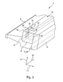
- the Fig. 1 to 3 show in different representation of a longitudinal seal 1 for a linear guide.
- the longitudinal seal 1 is e.g. manufactured as a two-component injection molded part and comprises a support 2 made of a comparatively hard plastic material, in particular PA, as well as a molded-on this sealing lip 3 made of a relatively soft and flexible elastomeric material.
- the carrier 2 has a flat elongated shape and forms on the side facing away from the sealing lip 3 side surface a back 4 of the longitudinal seal 1, with which this in a receptacle on a (not shown) carriage of the linear guide is insertable.
- a latching contour 5 is formed, which cooperates with corresponding latching means in the receptacle of the carriage to fix the longitudinal seal on the carriage.
- the sealing lip 3 is on a side facing away from the back 4 front 6 ( Fig. 2 ) of the carrier 2. Between the carrier 2 and the sealing lip 3 is an interface 7 ( Fig. 2 and 3 ) formed on the two parts, namely the carrier 2 and the sealing lip 3 collide directly.
- the interface 7 has 7 in cross-section according to Fig. 2 a graded contour.
- the interface 7 has a first vertical section 8 aligned with the front side 6, which merges via a horizontal section 9 into a second vertical section 10 set back in the direction of the back 4.
- the horizontal portion 8 defines an overlapping area where the carrier 2 and the sealing lip 3 overlap.
- a horizontal direction 11 is thus defined by the longer cross-sectional axis of the longitudinal seal 1, while a vertical direction 12 is defined by the shorter cross-sectional axis (or height).
- the direction perpendicular to the cross-sectional area is hereinafter referred to as the longitudinal direction 13 (FIG. Fig. 1 and 3 ) designated.
- a recess in the form of a bore 15 is introduced into the support 2 to enable each form-fitting engagement 14.
- the bore 15 opens to the horizontal portion of the interface 7 out with a comparatively small diameter. Starting from the interface 7, the bore 15 extends substantially in the vertical direction 12 and widens conically. The bore 15 passes completely through the carrier 2 and thus opens at an opposite to the horizontal portion 9 free surface 16 of the carrier 2 in an opening 17th
- the bore 15 is connected to a channel 18, which is introduced in the manner of a groove in the front side 6 of the carrier 2, and thus to the front 6 and the surface 16 is open.
- the channel 18 opens in the region of the vertical portion 8, and thus in particular at a distance from the mouth of the bore 15 again at the interface 7th
- Both the bore 15 and the channel 18 are filled with the material of the sealing lip 3.
- the recorded within the bore 15 part of this sealing lip material forms a form-fitting engaging in the carrier 2 projection of the sealing lip 3, which is hereinafter referred to as the first retaining projection 19.
- the part of the sealing lip material accommodated in the channel 18 forms a further projection of the sealing lip 3, which is referred to below as the second retaining projection 20.
- Both the first holding projection 19 and the second holding projection 20 are integrally connected to the sealing lip 3 at the interface 7.
- the first holding projection 19 and the second holding projection 20 also merge into one another within the carrier 2 in one piece.
- the first holding projection 19 and the second holding projection 20 thus form a loop 21 closed over the sealing lip 3, which loop wraps around a region of the carrier material arranged between the bore 15 and the channel 18 and which has a cross section has about the shape of a head about on the horizontal portion 9 of the interface 7 standing letter "V" through the longitudinal direction 1.
- Each of the interlocking engagements 14 thus forms a closed loop of material which can not be released without tearing off at least one of the retaining projections 19 and 20 from the sealing lip 3.
- For a good cohesion of the sealing lip 3 with the carrier 2 also contributes to the conical shape of the bore 15 and the corresponding conical shape of the first retaining projection 19, due to which the retaining projection 19 forms an undercut with the carrier 2.
- the 4 and 5 show a further Ausdusunsform the longitudinal seal 1.
- two sealing lips 3 are provided, which are fixed in juxtaposition to each other on the common carrier 2.
- a bridge-like projection 23 is formed on the support 2 on two opposite narrow sides 22, to which each one of the sealing lips 3 adjoins.
- Each of the projections 23 is formed from a number of along the narrow side 22 with spaced-lined columns 24 whose free ends are connected by a longitudinal strut 25 with each other.
- the columns 24 and the longitudinal strut 25 are in this case an integral part of the carrier 2 and also consist of the comparatively hard material material.
- the longitudinal strut 25 extends at a distance from the associated narrow side 22 of the carrier 2, so that each two adjacent columns 24 together with this connecting portion of the longitudinal strut 25 form a closed, integrally connected to the carrier 2 loop.
- Each projection 23 is completely encapsulated with the material of the associated sealing lip 3, so that the sealing material of the respective sealing lip 3 wraps closed around the loops formed by the columns 24 and the longitudinal strut 25 of the respective projection 23.
Applications Claiming Priority (1)
| Application Number | Priority Date | Filing Date | Title |
|---|---|---|---|
| DE200710008052 DE102007008052A1 (de) | 2007-02-15 | 2007-02-15 | Längsdichtung für eine Linearführung |
Publications (2)
| Publication Number | Publication Date |
|---|---|
| EP1959174A2 true EP1959174A2 (fr) | 2008-08-20 |
| EP1959174A3 EP1959174A3 (fr) | 2010-06-09 |
Family
ID=39319686
Family Applications (1)
| Application Number | Title | Priority Date | Filing Date |
|---|---|---|---|
| EP08002807A Withdrawn EP1959174A3 (fr) | 2007-02-15 | 2008-02-15 | Garniture d'étanchéité longitudinale pour un guidage linéaire |
Country Status (2)
| Country | Link |
|---|---|
| EP (1) | EP1959174A3 (fr) |
| DE (1) | DE102007008052A1 (fr) |
Cited By (1)
| Publication number | Priority date | Publication date | Assignee | Title |
|---|---|---|---|---|
| WO2010086143A1 (fr) * | 2009-01-27 | 2010-08-05 | Neo-Plastic Dr. Doetsch Diespeck Gmbh | Unité de palier comprenant un joint à structure sandwich |
Families Citing this family (7)
| Publication number | Priority date | Publication date | Assignee | Title |
|---|---|---|---|---|
| DE102009007048A1 (de) | 2009-01-27 | 2010-08-12 | Neo-Plastic Dr. Doetsch Diespeck Gmbh | Dichtung |
| DE102009052317A1 (de) | 2009-10-30 | 2011-05-12 | Neo-Plastic Dr. Doetsch Diespeck Gmbh | Sandwichdichtung mit durchgreifendem Kern und Prozesssteuerung mit Überlaufeinrichtung |
| DE102009052316A1 (de) | 2009-10-30 | 2011-05-12 | Neo-Plastic Dr. Doetsch Diespeck Gmbh | Sandwichdichtung mit verbreiteter Kopfform |
| WO2010086144A1 (fr) | 2009-01-27 | 2010-08-05 | Neo-Plastic Dr. Doetsch Diespeck Gmbh | Joint en sandwich avec noyau traversant et commande de procédé avec dispositif de trop-plein |
| DE102009007049A1 (de) | 2009-01-27 | 2010-08-12 | Neo-Plastic Dr. Doetsch Diespeck Gmbh | Dichtung |
| DE102009052318A1 (de) | 2009-10-30 | 2011-05-12 | Neo-Plastic Dr. Doetsch Diespeck Gmbh | Lagereinheit mit Sandwichdichtung |
| WO2010086145A1 (fr) | 2009-01-27 | 2010-08-05 | Neo-Plastic Dr. Doetsch Diespeck Gmbh | Joint à structure sandwich à tête élargie |
Citations (4)
| Publication number | Priority date | Publication date | Assignee | Title |
|---|---|---|---|---|
| FR1056617A (fr) * | 1952-05-16 | 1954-03-01 | Joint d'étanchéité pour arbres tournants | |
| DE2823135B1 (de) * | 1978-05-26 | 1979-09-20 | Goetze Ag | Stangendichtung |
| US5087130A (en) * | 1990-03-20 | 1992-02-11 | Nippon Seiko Kabushiki Kaisha | Under seal device of linear movement guide bearing |
| DE19821329A1 (de) * | 1998-05-13 | 1999-11-18 | Schaeffler Waelzlager Ohg | Linearwälzlager |
Family Cites Families (1)
| Publication number | Priority date | Publication date | Assignee | Title |
|---|---|---|---|---|
| DE4422842C1 (de) * | 1994-06-30 | 1995-08-17 | Sidler Gmbh & Co | Vorrichtung mit einem Gehäuse |
-
2007
- 2007-02-15 DE DE200710008052 patent/DE102007008052A1/de not_active Withdrawn
-
2008
- 2008-02-15 EP EP08002807A patent/EP1959174A3/fr not_active Withdrawn
Patent Citations (4)
| Publication number | Priority date | Publication date | Assignee | Title |
|---|---|---|---|---|
| FR1056617A (fr) * | 1952-05-16 | 1954-03-01 | Joint d'étanchéité pour arbres tournants | |
| DE2823135B1 (de) * | 1978-05-26 | 1979-09-20 | Goetze Ag | Stangendichtung |
| US5087130A (en) * | 1990-03-20 | 1992-02-11 | Nippon Seiko Kabushiki Kaisha | Under seal device of linear movement guide bearing |
| DE19821329A1 (de) * | 1998-05-13 | 1999-11-18 | Schaeffler Waelzlager Ohg | Linearwälzlager |
Cited By (1)
| Publication number | Priority date | Publication date | Assignee | Title |
|---|---|---|---|---|
| WO2010086143A1 (fr) * | 2009-01-27 | 2010-08-05 | Neo-Plastic Dr. Doetsch Diespeck Gmbh | Unité de palier comprenant un joint à structure sandwich |
Also Published As
| Publication number | Publication date |
|---|---|
| DE102007008052A1 (de) | 2008-08-21 |
| EP1959174A3 (fr) | 2010-06-09 |
Similar Documents
| Publication | Publication Date | Title |
|---|---|---|
| EP1959174A2 (fr) | Garniture d'étanchéité longitudinale pour un guidage linéaire | |
| DE102006048282B4 (de) | Linearführungseinrichtung | |
| DE102007056862A1 (de) | Linearrollenlager mit Umlenkstück | |
| DE4331014C2 (de) | Linearwälzlagerelement | |
| DE102005014745A1 (de) | Gerade Führung und untere Abdichtung | |
| DE19738988B4 (de) | Linearführungseinheit | |
| DE102008034922A1 (de) | Wälzlagerkäfig | |
| DE19815526B4 (de) | Linearführung mit Zwangsführung des Käfigs | |
| DE4103142A1 (de) | Schlossgehaeuse | |
| WO2006079395A2 (fr) | Palier a roulement lineaire | |
| DE3817391A1 (de) | Gleitschuh, insbesondere fuer fahrzeug-schiebedaecher oder -fensterheber | |
| DE102005028738B3 (de) | Dichtungsanordnung zum Abdichten einer Fensterscheibe mit einem Formteil | |
| DE3323347A1 (de) | Kugelumlauf-schraubgetriebe | |
| DE102006042696A1 (de) | Funktionseinheit | |
| DE102007056860A1 (de) | Linearwälzlager mit gemeinsamen Verschlusselementen für Wälzkörpereinfüllkanäle | |
| DE102006016946A1 (de) | Linearführungseinrichtung | |
| DE102008028110A1 (de) | Abstreiferanordnung | |
| DE102009007049A1 (de) | Dichtung | |
| DE102021105715B4 (de) | Linearwälzlager | |
| DE102007012746A1 (de) | Linearführungsvorrichtung | |
| DE202018106758U1 (de) | Paneel und damit versehene Offendachkonstruktion | |
| DE102009052318A1 (de) | Lagereinheit mit Sandwichdichtung | |
| DE4242774A1 (fr) | ||
| WO2010086145A1 (fr) | Joint à structure sandwich à tête élargie | |
| DE3202191C1 (de) | Laufschiene für eine Laufwagen-Zeichenmaschine |
Legal Events
| Date | Code | Title | Description |
|---|---|---|---|
| PUAI | Public reference made under article 153(3) epc to a published international application that has entered the european phase |
Free format text: ORIGINAL CODE: 0009012 |
|
| AK | Designated contracting states |
Kind code of ref document: A2 Designated state(s): AT BE BG CH CY CZ DE DK EE ES FI FR GB GR HR HU IE IS IT LI LT LU LV MC MT NL NO PL PT RO SE SI SK TR |
|
| AX | Request for extension of the european patent |
Extension state: AL BA MK RS |
|
| PUAL | Search report despatched |
Free format text: ORIGINAL CODE: 0009013 |
|
| AK | Designated contracting states |
Kind code of ref document: A3 Designated state(s): AT BE BG CH CY CZ DE DK EE ES FI FR GB GR HR HU IE IS IT LI LT LU LV MC MT NL NO PL PT RO SE SI SK TR |
|
| AX | Request for extension of the european patent |
Extension state: AL BA MK RS |
|
| AKY | No designation fees paid | ||
| STAA | Information on the status of an ep patent application or granted ep patent |
Free format text: STATUS: THE APPLICATION IS DEEMED TO BE WITHDRAWN |
|
| 18D | Application deemed to be withdrawn |
Effective date: 20101210 |
|
| REG | Reference to a national code |
Ref country code: DE Ref legal event code: R108 Effective date: 20110510 |