EP1947494B1 - Lens barrel and method for manufacturing the same - Google Patents
Lens barrel and method for manufacturing the same Download PDFInfo
- Publication number
- EP1947494B1 EP1947494B1 EP08000974A EP08000974A EP1947494B1 EP 1947494 B1 EP1947494 B1 EP 1947494B1 EP 08000974 A EP08000974 A EP 08000974A EP 08000974 A EP08000974 A EP 08000974A EP 1947494 B1 EP1947494 B1 EP 1947494B1
- Authority
- EP
- European Patent Office
- Prior art keywords
- gear
- lens
- lens barrel
- rotary
- stationary
- Prior art date
- Legal status (The legal status is an assumption and is not a legal conclusion. Google has not performed a legal analysis and makes no representation as to the accuracy of the status listed.)
- Not-in-force
Links
Images


Classifications
-
- G—PHYSICS
- G02—OPTICS
- G02B—OPTICAL ELEMENTS, SYSTEMS OR APPARATUS
- G02B7/00—Mountings, adjusting means, or light-tight connections, for optical elements
- G02B7/02—Mountings, adjusting means, or light-tight connections, for optical elements for lenses
- G02B7/04—Mountings, adjusting means, or light-tight connections, for optical elements for lenses with mechanism for focusing or varying magnification
- G02B7/10—Mountings, adjusting means, or light-tight connections, for optical elements for lenses with mechanism for focusing or varying magnification by relative axial movement of several lenses, e.g. of varifocal objective lens
- G02B7/102—Mountings, adjusting means, or light-tight connections, for optical elements for lenses with mechanism for focusing or varying magnification by relative axial movement of several lenses, e.g. of varifocal objective lens controlled by a microcomputer
Definitions
- the present invention relates to lens barrel and method for manufacturing the same.
- An interchangeable lens used for a camera system or the like is known, which is provided with a driving unit in which an actuator for driving a lens and a gear train for transferring an output of the actuator have been unitized in advance (for example, see Japanese Unexamined Patent Application Publication No. H6-011636 ).
- this interchangeable lens of the prior art may be subject to engagement failure between the gear train and a gear provided for a driven member due to an assembly error of the driving unit with respect to the stationary tube.
- An object of the present invention is to provide a lens barrel having an improved accuracy of assembly.
- a lens barrel comprising: a stationary part; a movable part provided movably relative to the stationary part, its movement causing a lens to move relative to the stationary part; a rotary member to transfer a driving force for moving the movable part relative to the stationary part to the movable part; and a supporting part provided at the stationary part integrally therewith to support a rotary axis of the rotary member.
- a lens may be accommodated in the stationary part.
- the gear train may be disposed in such a manner that the rotary axis is in parallel with an optical axis of the lens, and the rotary axes are arranged around an axis having its center at the optical axis or its vicinity.
- An output axis of the actuator and the rotary axis of the gear train may be arranged in parallel with an optical axis of the lens, and the output axis and the rotary axis are arranged around an axis having its center at the optical axis or its vicinity.
- a plurality of rotary members may be provided,
- the stationary part may be formed by a first part including a first supporting part to support a side of one end of the rotary axis and a second part including a second supporting part to support a side of the other end of the rotary axis.
- the method may include: providing a lens barrel side mount detachably engaged with a camera side mount provided at a camera body, and fixing the stationary part relative to the camera body.
- the method may include: providing a mount part for detachable fixation to a camera body, and fixing the stationary part relative to the mount part.
- the method may include: accommodating a lens in the stationary part.
- the method includes: providing an actuator to generate the driving force; and fixing the actuator to the supporting part.
- the rotary member may be a gear train including a first gear to which an output of the actuator is transferred and a final gear that can be meshed with a movable part side gear provided at the movable part.
- the method may include: arranging the gear train in such a manner that the rotary axis is in parallel with an optical axis of the lens, and arranging the rotary axes around an axis having its center at the optical axis or its vicinity.
- the method may include: arranging an output axis of the actuator and the rotary axis of the gear train in parallel with an optical axis of the lens, and arranging the output axis and the rotary axis around an axis having its center at the optical axis or its vicinity.
- the method may include: providing a plurality of said rotary members; arranging the plurality of rotary members in such a manner that the rotary axes are in parallel with the optical axis of the lens; and arranging these rotary axes around an axis having its center at the optical axis or its vicinity.
- the method may include: constituting the stationary part by a first part including a first supporting part to support a side of one end of the rotary axis, and a second part including a second supporting part to support a side of the other end of the rotary axis.
- the interchangeable lens of the first embodiment forms a camera system together with a camera body (not shown), and is configured to be detachably fitted to the camera body.
- the interchangeable lens can switch between an AF mode for performing a focusing operation according to publicly-known AF (auto focus) control, and an MF (manual focus) mode for performing a focusing operation in dependence on a photographer's manual input.
- AF auto focus
- MF manual focus
- Fig. 1 shows an exploded perspective view showing the interchangeable lens of the first embodiment.
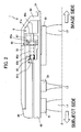
- Fig. 2 is a cross-partal view including the optical axis of the interchangeable lens shown in Fig. 1 .
- Fig. 2 shows a portion including a final gear (described later) provided on the interchangeable lens.
- Fig. 3 is an illustration showing a layout of each gear provided on the interchangeable lens of Fig. 2 , which is obtained by viewing the interchangeable lens in an optical axis.
- the interchangeable lens 1 is provided with a first lens unit L1, a second lens unit L2, a third lens unit L3, a first lens unit chamber 10, a second lens unit chamber 20, a third lens unit holding tube 30, a stationary tube 40, an outer tube 50, a focus operation tube 60, a zoom operation tube 70 and a driving part 80. It is noted that Fig. 1 is illustrated with the lens units L1-L3 and the zoom operation tube 70 omitted.
- the first lens unit L1, the second lens unit L2 and the third lens unit L3 form a zoom lens with a three-group construction, and are arranged in this order from the subject side toward the image side (the side of the photographer) along the optical axis.
- the interchangeable lens 1 is configured to move the first lens unit L1 and the third lens unit L3 along the optical axis at the time of a zoom operation, and to move the second lens unit L2 along the optical axis at the time of a focusing operation.
- the first lens unit chamber 10 and the second lens unit chamber 20 both are formed with a annulus shape, and are frame bodies for holding the first lens unit L1 and the second lens unit L2, respectively, in their internal diameter sides.
- the third lens unit holding tube 30 is a member formed with a annulus shape for holding the third lens unit L3.
- the stationary tube 40 is a tube body which is restricted in movement relative to the camera body in the state where the interchangeable lens 1 is fitted to the camera body.
- the above-mentioned first lens unit chamber 10, the second lens unit chamber 20 and the third lens unit holding tube 30 are each accommodated in an internal diameter side of the stationary tube 40.
- the center of this stationary tube 40 in a radial direction is substantially identical with the optical axis O of the lens units L1-L3.
- the outer tube 50 is a tube body forming a part of an outer surface of the interchangeable lens 1, which is disposed on an outer diameter side of the stationary tube 40.
- the outer tube 50 is formed with a larger size in its radial direction than the stationary tube 40, and a space S is formed between the outer tube 50 and the stationary tube 40.
- the outer tube 50 is formed with a size in its radial direction tapering from its intermediate portion to its end at the image side in the optical axis direction, and the vicinity of its end at the image side in the optical axis direction is connected to an end of the stationary tube 40 at the image side in the optical axis direction.
- the outer tube 50 is provided with a lens barrel side mount 51 on its end on the image side in the optical axis direction, in a portion closer to the image side in the optical axis direction than its connecting part with the stationary tube 40.
- the lens barrel side mount 51 is for detachably affixing the interchangeable lens 1 to the camera body in cooperation with a camera side mount (not shown) provided on the camera body.
- the stationary tube 40 is provided in state of being fixed to the lens barrel side mount 51. In other words, the stationary tube 40 is restricted in movement relative to the lens barrel side mount 51.
- the focus operation tube 60 is a tube body disposed on a side of an outer diameter of the stationary tube 40, and is placed substantially concentrically with the stationary tube 40.
- the focus operation tube 60 is set to be rotatable about the optical axis with respect to the stationary tube 40, and is intended to be manually rotated relative to the stationary tube 40 when the photographer carries out the MF operation.
- the interchangeable lens 1 is provided with a cam mechanism for focusing (not shown), whereby the second lens unit chamber 20 that holds the second lens unit L2 can move forward and backward along the optical axis direction in conjunction with the rotation of the focus operation tube 60.
- the zoom operation tube 70 is a tube body disposed on a side of an outer diameter of the focus operation tube 60, and is placed substantially concentrically with the stationary tube 40 and the focus operation tube 60.
- the zoom operation tube 70 can be rotated about the optical axis with respect to the stationary tube 40 by the photographer at the time of the zoom operation.
- the interchangeable lens 1 is provided with a cam mechanism for zooming (not shown), whereby the first lens unit L1 and the third lens unit L3 can move forward and backward along the optical axis direction in conjunction with the rotation of the zoom operation tube 70.
- the driving part 80 is a part for rotating the movable tube 60 about the optical axis in accordance with a signal from the AF control part (not shown) at the time of AF control.
- the driving part 80 is provided with a supporting part 81, an ultrasonic motor 82 (SWM 82), a pinion 83, an intermediate gear 84, a final gear 85, a focus operation tube side gear 86 and a cover 87, as shown in Fig. 1 .
- the supporting part 81 is a part for supporting an SWM 82, the intermediate gear 84 and the final gear 85 (described later) with respect to the stationary tube 40.
- the supporting part 81 is provided with an SWM supporting part 81a and a bearing part 81b.
- the SWM supporting part 81a supports the SWM 82, the intermediate gear 84 (described later) and a side of one end of the rotary axis 85c (see Fig. 2 ) of the final gear 85.
- the SWM supporting part 81a is a part formed protruding in a flanged shape to an outer diameter side thereof from a portion of an outer peripheral surface of the stationary tube 40, and is formed integrally with the stationary tube 40.
- the bearing part 81b supports the other end side of the rotary axis 85c of the final gear 85.
- the bearing part 81b is provided to be closer to a subject side in the optical axis direction than the SWM supporting part 81a, which is formed protruding to the outer diameter side from a portion of the outer peripheral surface of the stationary tube 40.
- This bearing part 81b is also formed integrally with the stationary tube 40.
- the SWM 82 is an electrical actuator for converting a progressive vibrational wave occurring in the expanding and contracting operation of a piezoelectric device into a rotational movement and outputting the result, and is provided with an output axis 82a.
- the SWM 82 is fixed to a surface portion of the SWM supporting part 81a facing toward the image side in the optical axis direction, and the above-mentioned output axis 82a protrudes closer to the image side in the optical axis direction than the SWM supporting part 81a and penetrates the SWM supporting part 81a.
- the pinion 83 is a gear provided at a tip portion of the output axis 82a of the SWM 82, and is intended to rotate integrally with the output axis 82a of the SWM 82.
- the intermediate gear 84 is a stepped gear disposed adjacently to the pinion 83, and is intended to reduce and transfer the output of the SWM 82 to the final gear 85 (described later) while decelerating.
- the rotary axis 84a (see Fig. 3 ) of the intermediate gear 84 is supported at one end by the SWM supporting part 81a.
- the final gear 85 is a gear for transferring the rotation of the intermediate gear 84 to the focus operation tube 60, which is provided with an input side gear 85a, an output side gear 85b and a rotary axis 85c.
- the input side gear 85a is a gear meshed with the intermediate gear 84.
- the output side gear 85b is a gear meshed with the focus operation tube side gear 86 described later.
- the input side gear 85a and the output side gear 85b are connected by the connecting tube 85d (see Fig. 2 ) formed in a hollow cylinder, and are rotated integrally.
- the rotary axis 85c penetrates the connecting tube 85d, one end of which is pivotally supported on the SWM supporting part 81a, and the other end of which is pivotally supported on the bearing part 81b.
- the focus operation tube side gear 86 is an internal gear (segment gear) formed in one portion of an inner peripheral surface of the focus operation tube 60, which is engaged with the output side gear 85b of the final gear 85.
- the output axis 82a of the SWM 82, the rotary axis 84a of the intermediate gear 84 and the rotary axis 85c of the final gear 85 mentioned above are each in parallel with the optical axis O. Then, these output axis 82a, and rotary axis 84a and 85c are arranged on an arc (a reference symbol A in Fig. 3 ) with its center in the optical axis O (see Fig. 3 ).
- the cover 87 protects the pinion 83, intermediate gear 84, final gear 85 mentioned above, which is secured to the stationary tube 40 by screws, not shown (see Fig. 1 ).
- the SWM 82 in the AF mode, for example, is driven in dependence on a signal from the AF control part provided at the camera body, and accordingly the output axis 82a of the SWM 82 rotates.
- the torque of the output axis 82a is transferred to the final gear 85 through the intermediate gear 84.
- the rotation of the final gear 85 causes the focus operation tube 60 to rotate about the optical axis.
- the rotation of the focus operation tube 60 causes the second lens unit chamber 20 holding the second lens unit L2 to move forward and backward in the optical axis direction through the focus cam mechanism, and whereby AF is carried out for the interchangeable lens 1.
- the focus operation tube 60 in the MF mode, is subjected to a rotary operation about the optical axis manually by the photographer.
- the focus operation tube 60 moves the second lens unit chamber 20 forward and backward in the optical direction based on its rotation as with the AF mode, and the MF is carried out for the interchangeable lens 1.
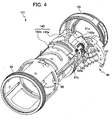
- Fig. 4 is an exploded perspective view showing an interchangeable lens of the second embodiment.
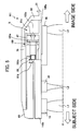
- Fig. 5 is a cross-partal view including an optical axis of the interchangeable lens shown in Fig. 4 .
- the interchangeable lens 101 of the second embodiment is different from the first embodiment in which the stationary tube 40 provided at the interchangeable lens 1 has a one-piece structure, in that the stationary tube 140 has a two-piece structure. Additionally, a final gear 185 provided at a driving part 180 has an input side gear 185a, an output side gear 185b and a rotary axis 185c formed integrally.
- the stationary tube 140 is provided with an image side tube part 140a and a subject side tube part 140b.
- the image side tube part 140a and the subject side tube part 140b show their tube bodies having almost the same size in the diameter direction, whose respective centers are substantially identical with the optical axis O.
- the image side tube part 140a is placed on the image side in the optical axis direction with respect to the subject side tube part 140b.
- the image side tube part 140a and the subject side tube part 140b are connected, for example by a screw (not shown), which is intended to enable handling them integrally.
- the supporting part 81a that pivotally supports the SWM 82, the intermediate gear 84 and a side of one end of the rotary axis 185c of the final gear 185 are provided at the image side tube part 140a integrally therewith, and the bearing part 81b for pivotally supporting a side of the other end of the rotary axis 185c of the final gear 185c is provided at the subject side tube part 140b integrally therewith.
- the rotary axis 85c of the final gear 85 is a member distinct from the input side gear 85a and the output side gear 85b in the first embodiment, whereas the final gear 185 in the second embodiment has the input side gear 185a, output side gear 185b and rotary axis 185c formed integrally with each other as shown in Fig. 5 .
- This final gear 185 has a construction in which the respective gears (185a and 185b) and the rotary axis 185c are unified, and thereby the gears and the rotary axis 185c do not jounce, thus making it possible to improve the accuracy of the mesh with the intermediate gear 84 and the focus operation tube side gear 86.
- the interchangeable lens 101 of the second embodiment also has a construction in which the stationary tube 140 is provided with the supporting part 81 supporting the driving part 180 (the SWM 82, the intermediate gear 84 and the final gear 185) integrally as with the interchangeable lens 1 of the first embodiment, and thereby it is possible to avoid engagement failures between the final gear 185 and the focus operation tube side gear 86, and to perform the AF with high accuracy.
- the stationary tube 140 has a 2-piece structure, the final gear 185 into which the gears (185a, 185b) and the rotary axis 185c are unified can readily be fitted to the stationary tube 140.
Landscapes
- Physics & Mathematics (AREA)
- Engineering & Computer Science (AREA)
- General Engineering & Computer Science (AREA)
- General Physics & Mathematics (AREA)
- Optics & Photonics (AREA)
- Lens Barrels (AREA)
- Eyeglasses (AREA)
Applications Claiming Priority (1)
| Application Number | Priority Date | Filing Date | Title |
|---|---|---|---|
| JP2007010423A JP4992435B2 (ja) | 2007-01-19 | 2007-01-19 | レンズ鏡筒 |
Publications (2)
| Publication Number | Publication Date |
|---|---|
| EP1947494A1 EP1947494A1 (en) | 2008-07-23 |
| EP1947494B1 true EP1947494B1 (en) | 2010-09-22 |
Family
ID=39203210
Family Applications (1)
| Application Number | Title | Priority Date | Filing Date |
|---|---|---|---|
| EP08000974A Not-in-force EP1947494B1 (en) | 2007-01-19 | 2008-01-18 | Lens barrel and method for manufacturing the same |
Country Status (5)
| Country | Link |
|---|---|
| US (1) | US7663810B2 (ja) |
| EP (1) | EP1947494B1 (ja) |
| JP (1) | JP4992435B2 (ja) |
| AT (1) | ATE482414T1 (ja) |
| DE (1) | DE602008002603D1 (ja) |
Families Citing this family (6)
| Publication number | Priority date | Publication date | Assignee | Title |
|---|---|---|---|---|
| JP5515321B2 (ja) * | 2009-02-24 | 2014-06-11 | コニカミノルタ株式会社 | レンズユニットおよびそれを用いる撮像装置 |
| US8807847B2 (en) | 2011-02-09 | 2014-08-19 | Panasonic Corporation | Lens barrel and imaging device |
| JP5884061B2 (ja) | 2011-02-09 | 2016-03-15 | パナソニックIpマネジメント株式会社 | レンズ鏡筒および撮像装置 |
| JP5950191B2 (ja) | 2011-08-24 | 2016-07-13 | パナソニックIpマネジメント株式会社 | レンズ鏡筒 |
| JP5935066B2 (ja) * | 2011-08-25 | 2016-06-15 | パナソニックIpマネジメント株式会社 | レンズ鏡筒 |
| CN111190318A (zh) * | 2020-02-21 | 2020-05-22 | 厦门力鼎光电股份有限公司 | 一种高精度快速自动聚焦机构 |
Family Cites Families (13)
| Publication number | Priority date | Publication date | Assignee | Title |
|---|---|---|---|---|
| DE2234728C3 (de) | 1972-07-14 | 1985-01-10 | Kabushiki Kaisha Sankyo Seiki Seisakusho, Nagano | Varioobjektiv mit Naheinstellbereich |
| DD105904A5 (ja) | 1972-12-06 | 1974-05-12 | ||
| DE3015398A1 (de) | 1980-04-22 | 1981-10-29 | Rollei-Werke Franke & Heidecke Gmbh & Co Kg, 3300 Braunschweig | Fokussiereinrichtung mit motorischem antrieb |
| JP3205031B2 (ja) | 1992-03-05 | 2001-09-04 | キヤノン株式会社 | レンズ鏡筒およびモーター駆動装置 |
| JP3399039B2 (ja) * | 1993-08-18 | 2003-04-21 | カシオ計算機株式会社 | レンズ駆動機構 |
| US5966248A (en) * | 1996-10-16 | 1999-10-12 | Nikon Corporation | Lens driving mechanism having an actuator |
| JP3911231B2 (ja) * | 2002-10-25 | 2007-05-09 | ペンタックス株式会社 | パワーマニュアル両用レンズ鏡筒 |
| US6879445B2 (en) * | 2002-10-25 | 2005-04-12 | Pentax Corporation | Power/manual lens barrel having a manual operating ring |
| JP4233394B2 (ja) | 2003-06-17 | 2009-03-04 | オリンパス株式会社 | レンズ装置及びそれを用いたデジタルカメラ |
| US7567284B2 (en) | 2003-06-17 | 2009-07-28 | Olympus Corporation | Encoder, lens-implement and digital camera |
| JP2006053307A (ja) * | 2004-08-11 | 2006-02-23 | Seiko Instruments Inc | 光学モジュール |
| JP4496139B2 (ja) | 2005-06-29 | 2010-07-07 | 株式会社東芝 | 降雨予報提供装置と降雨予報受信端末装置 |
| JP2007010934A (ja) * | 2005-06-30 | 2007-01-18 | Seiko Instruments Inc | 光学モジュール及びカメラモジュール |
-
2007
- 2007-01-19 JP JP2007010423A patent/JP4992435B2/ja not_active Expired - Fee Related
-
2008
- 2008-01-17 US US12/015,765 patent/US7663810B2/en not_active Expired - Fee Related
- 2008-01-18 AT AT08000974T patent/ATE482414T1/de not_active IP Right Cessation
- 2008-01-18 EP EP08000974A patent/EP1947494B1/en not_active Not-in-force
- 2008-01-18 DE DE602008002603T patent/DE602008002603D1/de active Active
Also Published As
| Publication number | Publication date |
|---|---|
| DE602008002603D1 (de) | 2010-11-04 |
| JP2008176128A (ja) | 2008-07-31 |
| JP4992435B2 (ja) | 2012-08-08 |
| EP1947494A1 (en) | 2008-07-23 |
| US20080192367A1 (en) | 2008-08-14 |
| US7663810B2 (en) | 2010-02-16 |
| ATE482414T1 (de) | 2010-10-15 |
Similar Documents
| Publication | Publication Date | Title |
|---|---|---|
| EP1947494B1 (en) | Lens barrel and method for manufacturing the same | |
| JP5832264B2 (ja) | 交換レンズ | |
| JP5448630B2 (ja) | レンズ鏡筒及びそれを有する光学機器 | |
| JP5836660B2 (ja) | レンズ鏡筒およびカメラシステム | |
| JP2002296482A (ja) | ズームレンズ鏡筒 | |
| US8117936B2 (en) | Gear support structure | |
| US9134589B2 (en) | Lens barrel | |
| JP6701797B2 (ja) | レンズ鏡筒及び光学機器 | |
| JP2002107598A (ja) | 沈胴式レンズ鏡筒及びこれを用いた光学機器 | |
| JP2000180689A (ja) | レンズ鏡胴 | |
| JP4501654B2 (ja) | ズームレンズ装置および携帯用電子機器 | |
| JP4763341B2 (ja) | レンズ鏡筒及び撮像装置 | |
| JP2006145562A (ja) | レンズ鏡筒 | |
| JP6535881B2 (ja) | レンズ鏡筒 | |
| JP4668167B2 (ja) | レンズ駆動装置 | |
| JP6257735B2 (ja) | 光学装置 | |
| US20220075140A1 (en) | Lens barrel and optical device | |
| JP2844594B2 (ja) | ズームレンズ鏡筒 | |
| JP4679083B2 (ja) | レンズ駆動装置 | |
| JP2021196472A (ja) | レンズ鏡筒及び撮像装置 | |
| JP5470714B2 (ja) | レンズ鏡筒、光学機器 | |
| JP2013003451A (ja) | レンズ鏡筒および光学機器 | |
| JP6022412B2 (ja) | レンズ装置 | |
| JP5122384B2 (ja) | ギヤ支持構造 | |
| JP2005215560A (ja) | レンズ装置、撮影システムおよび撮影装置 |
Legal Events
| Date | Code | Title | Description |
|---|---|---|---|
| PUAI | Public reference made under article 153(3) epc to a published international application that has entered the european phase |
Free format text: ORIGINAL CODE: 0009012 |
|
| AK | Designated contracting states |
Kind code of ref document: A1 Designated state(s): AT BE BG CH CY CZ DE DK EE ES FI FR GB GR HR HU IE IS IT LI LT LU LV MC MT NL NO PL PT RO SE SI SK TR |
|
| AX | Request for extension of the european patent |
Extension state: AL BA MK RS |
|
| 17P | Request for examination filed |
Effective date: 20090122 |
|
| 17Q | First examination report despatched |
Effective date: 20090225 |
|
| AKX | Designation fees paid |
Designated state(s): AT BE BG CH CY CZ DE DK EE ES FI FR GB GR HR HU IE IS IT LI LT LU LV MC MT NL NO PL PT RO SE SI SK TR |
|
| GRAP | Despatch of communication of intention to grant a patent |
Free format text: ORIGINAL CODE: EPIDOSNIGR1 |
|
| RAP1 | Party data changed (applicant data changed or rights of an application transferred) |
Owner name: NIKON CORPORATION |
|
| GRAS | Grant fee paid |
Free format text: ORIGINAL CODE: EPIDOSNIGR3 |
|
| GRAA | (expected) grant |
Free format text: ORIGINAL CODE: 0009210 |
|
| RIN1 | Information on inventor provided before grant (corrected) |
Inventor name: OKUYAMA, TEPPEI Inventor name: WATANABE, TSUNEO |
|
| AK | Designated contracting states |
Kind code of ref document: B1 Designated state(s): AT BE BG CH CY CZ DE DK EE ES FI FR GB GR HR HU IE IS IT LI LT LU LV MC MT NL NO PL PT RO SE SI SK TR |
|
| REG | Reference to a national code |
Ref country code: GB Ref legal event code: FG4D |
|
| REG | Reference to a national code |
Ref country code: CH Ref legal event code: EP |
|
| REG | Reference to a national code |
Ref country code: IE Ref legal event code: FG4D |
|
| REF | Corresponds to: |
Ref document number: 602008002603 Country of ref document: DE Date of ref document: 20101104 Kind code of ref document: P |
|
| PG25 | Lapsed in a contracting state [announced via postgrant information from national office to epo] |
Ref country code: NO Free format text: LAPSE BECAUSE OF FAILURE TO SUBMIT A TRANSLATION OF THE DESCRIPTION OR TO PAY THE FEE WITHIN THE PRESCRIBED TIME-LIMIT Effective date: 20101222 Ref country code: LT Free format text: LAPSE BECAUSE OF FAILURE TO SUBMIT A TRANSLATION OF THE DESCRIPTION OR TO PAY THE FEE WITHIN THE PRESCRIBED TIME-LIMIT Effective date: 20100922 Ref country code: FI Free format text: LAPSE BECAUSE OF FAILURE TO SUBMIT A TRANSLATION OF THE DESCRIPTION OR TO PAY THE FEE WITHIN THE PRESCRIBED TIME-LIMIT Effective date: 20100922 Ref country code: AT Free format text: LAPSE BECAUSE OF FAILURE TO SUBMIT A TRANSLATION OF THE DESCRIPTION OR TO PAY THE FEE WITHIN THE PRESCRIBED TIME-LIMIT Effective date: 20100922 |
|
| REG | Reference to a national code |
Ref country code: NL Ref legal event code: VDEP Effective date: 20100922 |
|
| LTIE | Lt: invalidation of european patent or patent extension |
Effective date: 20100922 |
|
| PG25 | Lapsed in a contracting state [announced via postgrant information from national office to epo] |
Ref country code: SI Free format text: LAPSE BECAUSE OF FAILURE TO SUBMIT A TRANSLATION OF THE DESCRIPTION OR TO PAY THE FEE WITHIN THE PRESCRIBED TIME-LIMIT Effective date: 20100922 Ref country code: PL Free format text: LAPSE BECAUSE OF FAILURE TO SUBMIT A TRANSLATION OF THE DESCRIPTION OR TO PAY THE FEE WITHIN THE PRESCRIBED TIME-LIMIT Effective date: 20100922 Ref country code: HR Free format text: LAPSE BECAUSE OF FAILURE TO SUBMIT A TRANSLATION OF THE DESCRIPTION OR TO PAY THE FEE WITHIN THE PRESCRIBED TIME-LIMIT Effective date: 20100922 |
|
| PG25 | Lapsed in a contracting state [announced via postgrant information from national office to epo] |
Ref country code: GR Free format text: LAPSE BECAUSE OF FAILURE TO SUBMIT A TRANSLATION OF THE DESCRIPTION OR TO PAY THE FEE WITHIN THE PRESCRIBED TIME-LIMIT Effective date: 20101223 Ref country code: LV Free format text: LAPSE BECAUSE OF FAILURE TO SUBMIT A TRANSLATION OF THE DESCRIPTION OR TO PAY THE FEE WITHIN THE PRESCRIBED TIME-LIMIT Effective date: 20100922 Ref country code: SE Free format text: LAPSE BECAUSE OF FAILURE TO SUBMIT A TRANSLATION OF THE DESCRIPTION OR TO PAY THE FEE WITHIN THE PRESCRIBED TIME-LIMIT Effective date: 20100922 |
|
| PG25 | Lapsed in a contracting state [announced via postgrant information from national office to epo] |
Ref country code: EE Free format text: LAPSE BECAUSE OF FAILURE TO SUBMIT A TRANSLATION OF THE DESCRIPTION OR TO PAY THE FEE WITHIN THE PRESCRIBED TIME-LIMIT Effective date: 20100922 Ref country code: PT Free format text: LAPSE BECAUSE OF FAILURE TO SUBMIT A TRANSLATION OF THE DESCRIPTION OR TO PAY THE FEE WITHIN THE PRESCRIBED TIME-LIMIT Effective date: 20110124 Ref country code: RO Free format text: LAPSE BECAUSE OF FAILURE TO SUBMIT A TRANSLATION OF THE DESCRIPTION OR TO PAY THE FEE WITHIN THE PRESCRIBED TIME-LIMIT Effective date: 20100922 Ref country code: IT Free format text: LAPSE BECAUSE OF FAILURE TO SUBMIT A TRANSLATION OF THE DESCRIPTION OR TO PAY THE FEE WITHIN THE PRESCRIBED TIME-LIMIT Effective date: 20100922 Ref country code: IS Free format text: LAPSE BECAUSE OF FAILURE TO SUBMIT A TRANSLATION OF THE DESCRIPTION OR TO PAY THE FEE WITHIN THE PRESCRIBED TIME-LIMIT Effective date: 20110122 Ref country code: CZ Free format text: LAPSE BECAUSE OF FAILURE TO SUBMIT A TRANSLATION OF THE DESCRIPTION OR TO PAY THE FEE WITHIN THE PRESCRIBED TIME-LIMIT Effective date: 20100922 Ref country code: NL Free format text: LAPSE BECAUSE OF FAILURE TO SUBMIT A TRANSLATION OF THE DESCRIPTION OR TO PAY THE FEE WITHIN THE PRESCRIBED TIME-LIMIT Effective date: 20100922 Ref country code: SK Free format text: LAPSE BECAUSE OF FAILURE TO SUBMIT A TRANSLATION OF THE DESCRIPTION OR TO PAY THE FEE WITHIN THE PRESCRIBED TIME-LIMIT Effective date: 20100922 |
|
| PG25 | Lapsed in a contracting state [announced via postgrant information from national office to epo] |
Ref country code: BE Free format text: LAPSE BECAUSE OF FAILURE TO SUBMIT A TRANSLATION OF THE DESCRIPTION OR TO PAY THE FEE WITHIN THE PRESCRIBED TIME-LIMIT Effective date: 20100922 |
|
| PG25 | Lapsed in a contracting state [announced via postgrant information from national office to epo] |
Ref country code: ES Free format text: LAPSE BECAUSE OF FAILURE TO SUBMIT A TRANSLATION OF THE DESCRIPTION OR TO PAY THE FEE WITHIN THE PRESCRIBED TIME-LIMIT Effective date: 20110102 |
|
| PLBE | No opposition filed within time limit |
Free format text: ORIGINAL CODE: 0009261 |
|
| STAA | Information on the status of an ep patent application or granted ep patent |
Free format text: STATUS: NO OPPOSITION FILED WITHIN TIME LIMIT |
|
| 26N | No opposition filed |
Effective date: 20110623 |
|
| PG25 | Lapsed in a contracting state [announced via postgrant information from national office to epo] |
Ref country code: MC Free format text: LAPSE BECAUSE OF NON-PAYMENT OF DUE FEES Effective date: 20110131 Ref country code: DK Free format text: LAPSE BECAUSE OF FAILURE TO SUBMIT A TRANSLATION OF THE DESCRIPTION OR TO PAY THE FEE WITHIN THE PRESCRIBED TIME-LIMIT Effective date: 20100922 |
|
| REG | Reference to a national code |
Ref country code: DE Ref legal event code: R097 Ref document number: 602008002603 Country of ref document: DE Effective date: 20110623 |
|
| REG | Reference to a national code |
Ref country code: IE Ref legal event code: MM4A |
|
| PG25 | Lapsed in a contracting state [announced via postgrant information from national office to epo] |
Ref country code: MT Free format text: LAPSE BECAUSE OF FAILURE TO SUBMIT A TRANSLATION OF THE DESCRIPTION OR TO PAY THE FEE WITHIN THE PRESCRIBED TIME-LIMIT Effective date: 20100922 |
|
| PG25 | Lapsed in a contracting state [announced via postgrant information from national office to epo] |
Ref country code: IE Free format text: LAPSE BECAUSE OF NON-PAYMENT OF DUE FEES Effective date: 20110118 |
|
| REG | Reference to a national code |
Ref country code: CH Ref legal event code: PL |
|
| PG25 | Lapsed in a contracting state [announced via postgrant information from national office to epo] |
Ref country code: LI Free format text: LAPSE BECAUSE OF NON-PAYMENT OF DUE FEES Effective date: 20120131 Ref country code: CH Free format text: LAPSE BECAUSE OF NON-PAYMENT OF DUE FEES Effective date: 20120131 |
|
| PG25 | Lapsed in a contracting state [announced via postgrant information from national office to epo] |
Ref country code: CY Free format text: LAPSE BECAUSE OF FAILURE TO SUBMIT A TRANSLATION OF THE DESCRIPTION OR TO PAY THE FEE WITHIN THE PRESCRIBED TIME-LIMIT Effective date: 20100922 Ref country code: LU Free format text: LAPSE BECAUSE OF NON-PAYMENT OF DUE FEES Effective date: 20110118 |
|
| PG25 | Lapsed in a contracting state [announced via postgrant information from national office to epo] |
Ref country code: TR Free format text: LAPSE BECAUSE OF FAILURE TO SUBMIT A TRANSLATION OF THE DESCRIPTION OR TO PAY THE FEE WITHIN THE PRESCRIBED TIME-LIMIT Effective date: 20100922 Ref country code: BG Free format text: LAPSE BECAUSE OF FAILURE TO SUBMIT A TRANSLATION OF THE DESCRIPTION OR TO PAY THE FEE WITHIN THE PRESCRIBED TIME-LIMIT Effective date: 20101222 |
|
| PG25 | Lapsed in a contracting state [announced via postgrant information from national office to epo] |
Ref country code: HU Free format text: LAPSE BECAUSE OF FAILURE TO SUBMIT A TRANSLATION OF THE DESCRIPTION OR TO PAY THE FEE WITHIN THE PRESCRIBED TIME-LIMIT Effective date: 20100922 |
|
| REG | Reference to a national code |
Ref country code: FR Ref legal event code: PLFP Year of fee payment: 9 |
|
| REG | Reference to a national code |
Ref country code: FR Ref legal event code: PLFP Year of fee payment: 10 |
|
| REG | Reference to a national code |
Ref country code: FR Ref legal event code: PLFP Year of fee payment: 11 |
|
| PGFP | Annual fee paid to national office [announced via postgrant information from national office to epo] |
Ref country code: FR Payment date: 20191216 Year of fee payment: 13 |
|
| PGFP | Annual fee paid to national office [announced via postgrant information from national office to epo] |
Ref country code: GB Payment date: 20200113 Year of fee payment: 13 Ref country code: DE Payment date: 20200107 Year of fee payment: 13 |
|
| REG | Reference to a national code |
Ref country code: DE Ref legal event code: R119 Ref document number: 602008002603 Country of ref document: DE |
|
| GBPC | Gb: european patent ceased through non-payment of renewal fee |
Effective date: 20210118 |
|
| PG25 | Lapsed in a contracting state [announced via postgrant information from national office to epo] |
Ref country code: FR Free format text: LAPSE BECAUSE OF NON-PAYMENT OF DUE FEES Effective date: 20210131 |
|
| PG25 | Lapsed in a contracting state [announced via postgrant information from national office to epo] |
Ref country code: DE Free format text: LAPSE BECAUSE OF NON-PAYMENT OF DUE FEES Effective date: 20210803 Ref country code: GB Free format text: LAPSE BECAUSE OF NON-PAYMENT OF DUE FEES Effective date: 20210118 |