EP1946830B1 - Mikroreaktor - Google Patents
Mikroreaktor Download PDFInfo
- Publication number
- EP1946830B1 EP1946830B1 EP06821911.2A EP06821911A EP1946830B1 EP 1946830 B1 EP1946830 B1 EP 1946830B1 EP 06821911 A EP06821911 A EP 06821911A EP 1946830 B1 EP1946830 B1 EP 1946830B1
- Authority
- EP
- European Patent Office
- Prior art keywords
- flow path
- reagent
- section
- microreactor
- driving solution
- Prior art date
- Legal status (The legal status is an assumption and is not a legal conclusion. Google has not performed a legal analysis and makes no representation as to the accuracy of the status listed.)
- Not-in-force
Links
Images


Classifications
-
- B—PERFORMING OPERATIONS; TRANSPORTING
- B01—PHYSICAL OR CHEMICAL PROCESSES OR APPARATUS IN GENERAL
- B01L—CHEMICAL OR PHYSICAL LABORATORY APPARATUS FOR GENERAL USE
- B01L3/00—Containers or dishes for laboratory use, e.g. laboratory glassware; Droppers
- B01L3/50—Containers for the purpose of retaining a material to be analysed, e.g. test tubes
- B01L3/502—Containers for the purpose of retaining a material to be analysed, e.g. test tubes with fluid transport, e.g. in multi-compartment structures
- B01L3/5027—Containers for the purpose of retaining a material to be analysed, e.g. test tubes with fluid transport, e.g. in multi-compartment structures by integrated microfluidic structures, i.e. dimensions of channels and chambers are such that surface tension forces are important, e.g. lab-on-a-chip
- B01L3/502738—Containers for the purpose of retaining a material to be analysed, e.g. test tubes with fluid transport, e.g. in multi-compartment structures by integrated microfluidic structures, i.e. dimensions of channels and chambers are such that surface tension forces are important, e.g. lab-on-a-chip characterised by integrated valves
-
- B—PERFORMING OPERATIONS; TRANSPORTING
- B01—PHYSICAL OR CHEMICAL PROCESSES OR APPARATUS IN GENERAL
- B01F—MIXING, e.g. DISSOLVING, EMULSIFYING OR DISPERSING
- B01F25/00—Flow mixers; Mixers for falling materials, e.g. solid particles
- B01F25/40—Static mixers
- B01F25/42—Static mixers in which the mixing is affected by moving the components jointly in changing directions, e.g. in tubes provided with baffles or obstructions
- B01F25/43—Mixing tubes, e.g. wherein the material is moved in a radial or partly reversed direction
- B01F25/433—Mixing tubes wherein the shape of the tube influences the mixing, e.g. mixing tubes with varying cross-section or provided with inwardly extending profiles
- B01F25/4331—Mixers with bended, curved, coiled, wounded mixing tubes or comprising elements for bending the flow
-
- B—PERFORMING OPERATIONS; TRANSPORTING
- B01—PHYSICAL OR CHEMICAL PROCESSES OR APPARATUS IN GENERAL
- B01J—CHEMICAL OR PHYSICAL PROCESSES, e.g. CATALYSIS OR COLLOID CHEMISTRY; THEIR RELEVANT APPARATUS
- B01J19/00—Chemical, physical or physico-chemical processes in general; Their relevant apparatus
- B01J19/0093—Microreactors, e.g. miniaturised or microfabricated reactors
-
- B—PERFORMING OPERATIONS; TRANSPORTING
- B01—PHYSICAL OR CHEMICAL PROCESSES OR APPARATUS IN GENERAL
- B01L—CHEMICAL OR PHYSICAL LABORATORY APPARATUS FOR GENERAL USE
- B01L3/00—Containers or dishes for laboratory use, e.g. laboratory glassware; Droppers
- B01L3/50—Containers for the purpose of retaining a material to be analysed, e.g. test tubes
- B01L3/502—Containers for the purpose of retaining a material to be analysed, e.g. test tubes with fluid transport, e.g. in multi-compartment structures
- B01L3/5027—Containers for the purpose of retaining a material to be analysed, e.g. test tubes with fluid transport, e.g. in multi-compartment structures by integrated microfluidic structures, i.e. dimensions of channels and chambers are such that surface tension forces are important, e.g. lab-on-a-chip
- B01L3/502723—Containers for the purpose of retaining a material to be analysed, e.g. test tubes with fluid transport, e.g. in multi-compartment structures by integrated microfluidic structures, i.e. dimensions of channels and chambers are such that surface tension forces are important, e.g. lab-on-a-chip characterised by venting arrangements
-
- B—PERFORMING OPERATIONS; TRANSPORTING
- B01—PHYSICAL OR CHEMICAL PROCESSES OR APPARATUS IN GENERAL
- B01L—CHEMICAL OR PHYSICAL LABORATORY APPARATUS FOR GENERAL USE
- B01L3/00—Containers or dishes for laboratory use, e.g. laboratory glassware; Droppers
- B01L3/50—Containers for the purpose of retaining a material to be analysed, e.g. test tubes
- B01L3/502—Containers for the purpose of retaining a material to be analysed, e.g. test tubes with fluid transport, e.g. in multi-compartment structures
- B01L3/5027—Containers for the purpose of retaining a material to be analysed, e.g. test tubes with fluid transport, e.g. in multi-compartment structures by integrated microfluidic structures, i.e. dimensions of channels and chambers are such that surface tension forces are important, e.g. lab-on-a-chip
- B01L3/502746—Containers for the purpose of retaining a material to be analysed, e.g. test tubes with fluid transport, e.g. in multi-compartment structures by integrated microfluidic structures, i.e. dimensions of channels and chambers are such that surface tension forces are important, e.g. lab-on-a-chip characterised by the means for controlling flow resistance, e.g. flow controllers, baffles or throttle valves
-
- F—MECHANICAL ENGINEERING; LIGHTING; HEATING; WEAPONS; BLASTING
- F16—ENGINEERING ELEMENTS AND UNITS; GENERAL MEASURES FOR PRODUCING AND MAINTAINING EFFECTIVE FUNCTIONING OF MACHINES OR INSTALLATIONS; THERMAL INSULATION IN GENERAL
- F16K—VALVES; TAPS; COCKS; ACTUATING-FLOATS; DEVICES FOR VENTING OR AERATING
- F16K99/00—Subject matter not provided for in other groups of this subclass
- F16K99/0001—Microvalves
- F16K99/0003—Constructional types of microvalves; Details of the cutting-off member
- F16K99/0017—Capillary or surface tension valves, e.g. using electro-wetting or electro-capillarity effects
-
- F—MECHANICAL ENGINEERING; LIGHTING; HEATING; WEAPONS; BLASTING
- F16—ENGINEERING ELEMENTS AND UNITS; GENERAL MEASURES FOR PRODUCING AND MAINTAINING EFFECTIVE FUNCTIONING OF MACHINES OR INSTALLATIONS; THERMAL INSULATION IN GENERAL
- F16K—VALVES; TAPS; COCKS; ACTUATING-FLOATS; DEVICES FOR VENTING OR AERATING
- F16K99/00—Subject matter not provided for in other groups of this subclass
- F16K99/0001—Microvalves
- F16K99/0034—Operating means specially adapted for microvalves
- F16K99/0055—Operating means specially adapted for microvalves actuated by fluids
- F16K99/0057—Operating means specially adapted for microvalves actuated by fluids the fluid being the circulating fluid itself, e.g. check valves
-
- B—PERFORMING OPERATIONS; TRANSPORTING
- B01—PHYSICAL OR CHEMICAL PROCESSES OR APPARATUS IN GENERAL
- B01F—MIXING, e.g. DISSOLVING, EMULSIFYING OR DISPERSING
- B01F25/00—Flow mixers; Mixers for falling materials, e.g. solid particles
- B01F25/40—Static mixers
- B01F25/42—Static mixers in which the mixing is affected by moving the components jointly in changing directions, e.g. in tubes provided with baffles or obstructions
-
- B—PERFORMING OPERATIONS; TRANSPORTING
- B01—PHYSICAL OR CHEMICAL PROCESSES OR APPARATUS IN GENERAL
- B01F—MIXING, e.g. DISSOLVING, EMULSIFYING OR DISPERSING
- B01F33/00—Other mixers; Mixing plants; Combinations of mixers
- B01F33/30—Micromixers
-
- B—PERFORMING OPERATIONS; TRANSPORTING
- B01—PHYSICAL OR CHEMICAL PROCESSES OR APPARATUS IN GENERAL
- B01J—CHEMICAL OR PHYSICAL PROCESSES, e.g. CATALYSIS OR COLLOID CHEMISTRY; THEIR RELEVANT APPARATUS
- B01J2219/00—Chemical, physical or physico-chemical processes in general; Their relevant apparatus
- B01J2219/00781—Aspects relating to microreactors
- B01J2219/00891—Feeding or evacuation
-
- B—PERFORMING OPERATIONS; TRANSPORTING
- B01—PHYSICAL OR CHEMICAL PROCESSES OR APPARATUS IN GENERAL
- B01L—CHEMICAL OR PHYSICAL LABORATORY APPARATUS FOR GENERAL USE
- B01L2200/00—Solutions for specific problems relating to chemical or physical laboratory apparatus
- B01L2200/06—Fluid handling related problems
- B01L2200/0684—Venting, avoiding backpressure, avoid gas bubbles
-
- B—PERFORMING OPERATIONS; TRANSPORTING
- B01—PHYSICAL OR CHEMICAL PROCESSES OR APPARATUS IN GENERAL
- B01L—CHEMICAL OR PHYSICAL LABORATORY APPARATUS FOR GENERAL USE
- B01L2200/00—Solutions for specific problems relating to chemical or physical laboratory apparatus
- B01L2200/16—Reagents, handling or storing thereof
-
- B—PERFORMING OPERATIONS; TRANSPORTING
- B01—PHYSICAL OR CHEMICAL PROCESSES OR APPARATUS IN GENERAL
- B01L—CHEMICAL OR PHYSICAL LABORATORY APPARATUS FOR GENERAL USE
- B01L2300/00—Additional constructional details
- B01L2300/08—Geometry, shape and general structure
- B01L2300/0809—Geometry, shape and general structure rectangular shaped
- B01L2300/0816—Cards, e.g. flat sample carriers usually with flow in two horizontal directions
-
- B—PERFORMING OPERATIONS; TRANSPORTING
- B01—PHYSICAL OR CHEMICAL PROCESSES OR APPARATUS IN GENERAL
- B01L—CHEMICAL OR PHYSICAL LABORATORY APPARATUS FOR GENERAL USE
- B01L2300/00—Additional constructional details
- B01L2300/08—Geometry, shape and general structure
- B01L2300/0861—Configuration of multiple channels and/or chambers in a single devices
- B01L2300/0867—Multiple inlets and one sample wells, e.g. mixing, dilution
-
- B—PERFORMING OPERATIONS; TRANSPORTING
- B01—PHYSICAL OR CHEMICAL PROCESSES OR APPARATUS IN GENERAL
- B01L—CHEMICAL OR PHYSICAL LABORATORY APPARATUS FOR GENERAL USE
- B01L2300/00—Additional constructional details
- B01L2300/18—Means for temperature control
- B01L2300/1805—Conductive heating, heat from thermostatted solids is conducted to receptacles, e.g. heating plates, blocks
- B01L2300/1822—Conductive heating, heat from thermostatted solids is conducted to receptacles, e.g. heating plates, blocks using Peltier elements
-
- B—PERFORMING OPERATIONS; TRANSPORTING
- B01—PHYSICAL OR CHEMICAL PROCESSES OR APPARATUS IN GENERAL
- B01L—CHEMICAL OR PHYSICAL LABORATORY APPARATUS FOR GENERAL USE
- B01L2400/00—Moving or stopping fluids
- B01L2400/04—Moving fluids with specific forces or mechanical means
- B01L2400/0403—Moving fluids with specific forces or mechanical means specific forces
- B01L2400/0433—Moving fluids with specific forces or mechanical means specific forces vibrational forces
- B01L2400/0439—Moving fluids with specific forces or mechanical means specific forces vibrational forces ultrasonic vibrations, vibrating piezo elements
-
- B—PERFORMING OPERATIONS; TRANSPORTING
- B01—PHYSICAL OR CHEMICAL PROCESSES OR APPARATUS IN GENERAL
- B01L—CHEMICAL OR PHYSICAL LABORATORY APPARATUS FOR GENERAL USE
- B01L2400/00—Moving or stopping fluids
- B01L2400/04—Moving fluids with specific forces or mechanical means
- B01L2400/0475—Moving fluids with specific forces or mechanical means specific mechanical means and fluid pressure
- B01L2400/0487—Moving fluids with specific forces or mechanical means specific mechanical means and fluid pressure fluid pressure, pneumatics
-
- B—PERFORMING OPERATIONS; TRANSPORTING
- B01—PHYSICAL OR CHEMICAL PROCESSES OR APPARATUS IN GENERAL
- B01L—CHEMICAL OR PHYSICAL LABORATORY APPARATUS FOR GENERAL USE
- B01L2400/00—Moving or stopping fluids
- B01L2400/06—Valves, specific forms thereof
- B01L2400/0688—Valves, specific forms thereof surface tension valves, capillary stop, capillary break
-
- B—PERFORMING OPERATIONS; TRANSPORTING
- B01—PHYSICAL OR CHEMICAL PROCESSES OR APPARATUS IN GENERAL
- B01L—CHEMICAL OR PHYSICAL LABORATORY APPARATUS FOR GENERAL USE
- B01L2400/00—Moving or stopping fluids
- B01L2400/08—Regulating or influencing the flow resistance
- B01L2400/084—Passive control of flow resistance
-
- F—MECHANICAL ENGINEERING; LIGHTING; HEATING; WEAPONS; BLASTING
- F16—ENGINEERING ELEMENTS AND UNITS; GENERAL MEASURES FOR PRODUCING AND MAINTAINING EFFECTIVE FUNCTIONING OF MACHINES OR INSTALLATIONS; THERMAL INSULATION IN GENERAL
- F16K—VALVES; TAPS; COCKS; ACTUATING-FLOATS; DEVICES FOR VENTING OR AERATING
- F16K99/00—Subject matter not provided for in other groups of this subclass
- F16K2099/0082—Microvalves adapted for a particular use
- F16K2099/0084—Chemistry or biology, e.g. "lab-on-a-chip" technology
-
- F—MECHANICAL ENGINEERING; LIGHTING; HEATING; WEAPONS; BLASTING
- F16—ENGINEERING ELEMENTS AND UNITS; GENERAL MEASURES FOR PRODUCING AND MAINTAINING EFFECTIVE FUNCTIONING OF MACHINES OR INSTALLATIONS; THERMAL INSULATION IN GENERAL
- F16K—VALVES; TAPS; COCKS; ACTUATING-FLOATS; DEVICES FOR VENTING OR AERATING
- F16K99/00—Subject matter not provided for in other groups of this subclass
- F16K99/0001—Microvalves
- F16K99/0034—Operating means specially adapted for microvalves
-
- Y—GENERAL TAGGING OF NEW TECHNOLOGICAL DEVELOPMENTS; GENERAL TAGGING OF CROSS-SECTIONAL TECHNOLOGIES SPANNING OVER SEVERAL SECTIONS OF THE IPC; TECHNICAL SUBJECTS COVERED BY FORMER USPC CROSS-REFERENCE ART COLLECTIONS [XRACs] AND DIGESTS
- Y10—TECHNICAL SUBJECTS COVERED BY FORMER USPC
- Y10T—TECHNICAL SUBJECTS COVERED BY FORMER US CLASSIFICATION
- Y10T436/00—Chemistry: analytical and immunological testing
- Y10T436/25—Chemistry: analytical and immunological testing including sample preparation
- Y10T436/2575—Volumetric liquid transfer
Definitions
- the present invention relates to a microreactor which is employed for inspection and analysis of a biological substance by using gene amplification reaction, antigen-antibody reaction or the like, inspection and analysis of other chemical substances, and chemical synthesis of a target compound by organic synthesis.
- micromachining technology and ultra microfabrication technology have made it possible to develop a one-chip system where conventional apparatuses or means (e.g., pump, valve, flow path and sensor) for sample preparation, chemical analysis and chemical synthesis are formed into a microstructure (Patent Document 1).
- This system is also called the ⁇ -TAS (Micro Total Analysis System), bioreactor, lab-on-chips or biochip.
- the application of this system is anticipated to bring about a great success in the field of medical inspection, diagnostic field, environmental measuring field, and agricultural production field.
- the chip for analysis is required to provide superb quantitative property, accuracy and economy in analysis.
- it is important to establish a liquid feed system characterized by a simple structure and high reliability.
- a micro-fluid control elements characterized by a high degree of accuracy and reliability.
- the present inventors have already proposed a micro-pump system and its control method preferably used to achieve these objects (Patent Documents 2 through 4).
- the aforementioned analysis chip is preferred to permit reaction between a sample and a mixed reagent prepared by mixing a plurality of reagents.
- a so-called micro-reactor requires that various forms of mixing operation such as mixing between reagents, mixing between a reagent and sample are performed within a single chip. This requires a high degree of accuracy in the feed of reagents and others, as exemplified by exact timing for confluence with various reagents and others, and feeding of reagents and others under a predetermined pressure. Failure of high-precision feed of the reagents and others will lead to adverse effect upon reaction and result of detection.
- a liquid feed method for micro-fluid device where by using an oily driving solution, an aqueous solution incompatible with the oily solution is pushed downstream, whereby the liquid is fed (Patent Document 5) .
- the present inventors have already proposed in the JP-2005-276799 a technology to solve the aforementioned problems.
- the technology proposed therein when the reagent filled in the flow path of the microreactor is pushed out downstream by the aqueous driving solution and is fed out, in the initial stage before the driving solution is brought into contact with the reagent, air presented between them is allowed to escape through an air evacuation flow path characterized by a small diameter and a hydrophobic inner surface, whereby air bubbles are discharged to the outside.
- the leakage of the driving solution from the air evacuation flow path cannot be completely blocked by the water repellency.
- the driving solution may leak by liquid pressure.
- An object of the present invention is to provide a microreactor for causing reaction between a sample and mixed reagent prepared by mixing a plurality of reagents, wherein this microreactor provides high-precision control of the timing for mixing liquids such as reagents, the mixing ratio of liquids and liquid feed pressure, without allowing air to be entrapped between a driving solution and the reagent.
- a flow path resistance of the air evacuation flow path when the liquid flows therethrough is preferably 10 times or higher than a flow path resistance of the flow channel when the liquid flows therethrough, the flow channel which starts from the branch section as a starting point and includes from the reagent storage section to the reagent feed-out flow path.
- the "reagent feed-out flow path" can be exemplified by a flow path from the outlet of the reagent storage section to the junction for confluence with other reagents, a flow path to a reaction section where a reagent is fixed in the chip, and a flow path to the heating section for activating a biochemical reaction.
- an air evacuation flow path is provided on the upstream side from the inlet of the reagent storage section. This arrangement ensures the existing air between the liquids to be removed from the air evacuation flow path in the initial stage where an external pump is connected to the microreactor to feed the driving solution into the inlet.
- the flow path resistance when a liquid flows into the air evacuation flow path is greater than the flow path resistance of the flow channel when a liquid flows through the flow channel from the aforementioned reagent storage section to the reagent feed-out flow path where the aforementioned branch section is assumed as the starting point. Accordingly, even if a leakage of driving solution from the air evacuation flow path occurs after air has been removed from this air evacuation flow path, the amount of the leakage can be lowered. Further, if the flow path resistance of the evacuation flow path when a liquid flows through the air evacuation flow path is at least 10 times greater, the aforementioned leakage can be reduced to a very small level.
- this structure ensures high-precision control of timing for mixing liquids such as reagents, mixing ratio of liquids and liquid feed pressure.
- a flow path resistance of the air evacuation flow path when an air flows therethrough is preferably smaller than a flow path resistance of the flow channel when the liquid flows therethrough, the flow channel which starts from the branch section as a starting point and includes from the reagent storage section to the reagent feed-out flow path.
- This arrangement allows the driving solution to flow into the branch flow path without pushing out a reagent in the reagent storage section in the initial stage of the operation of feeding the driving solution into the reagent storage section, and the driving solution fills the branch flow path while removing air from the air evacuation flow path.
- the present invention capable of ensuring complete evacuation of air bubbles provides high-precision control of timing for mixing liquids such as reagents, mixing ratio of liquids and liquid feed pressure.
- the microreactor comprises:
- the driving solution in the initial stage of feeding out the driving solution into the reagent storage section, the driving solution enters the branch flow path without pushing out the reagent beyond the water-repellent valve at the outlet of the reagent storage section and fills the branch flow path while evacuating air from the air evacuation flow path, because the flow rate of the driving solution is assumed as Q ⁇ P / R A .
- the flow rate of the driving solution is assumed as P / R L ⁇ Q. Accordingly, when the driving solution flows into the air evacuation flow path after complete evacuation of the air, it pushed the reagent out beyond the water-repellent valve.
- this arrangement capable of ensuring complete evacuation of air bubbles provides high-precision control of timing for mixing liquids such as reagents, mixing ratio of liquids and liquid feed pressure.
- microreactor of the present invention comprising:
- the ration between the volume of the driving solution leaking out of the air evacuation flow path and the volume of the reagent flowing into the junction is substantially the same. This ensures easy control of the micro-pump as an external pump.
- the voltage control of each of the micro-pumps for pushing out various reagents by feeding out the driving solution can be simplified, for example, unified. There is no need of using complicated control for each micro-pump to keep the reagent mixing ratio constant.
- the microreactor of the present invention comprises: a reservoir section which is provided on an exit side of the air evacuation flow path for reserving the driving solution fed out through the air evacuation flow path.
- Installation of a liquid reservoir section having a predetermined capacity ensures that the driving solution leaking from the air evacuation flow path can be accommodated into a predetermined site. This eliminates the possibility of the driving solution leaking from the chip or moving to an unwanted site.
- the aforementioned invention preferably comprises:
- the storage chamber of the microreactor of the current invention can be filled with a reagent.
- the microreactor of the present invention ensures high-precision control of timing for mixing liquids such as reagents, mixing ratio of liquids and liquid feed pressure, without air being caught between the driving solution and reagent.
- a microreactor of the present invention is used to cause reaction between sample and reagent for various forms of inspection, chemical analysis, chemical synthesis and processing and separation of the sample in a minute flow path or structural member.
- microreactor of the present invention includes inspection and analysis of the biological substance by gene amplification reaction and antigen-antibody reaction, chemical synthesis of the target compound by the inspection and analysis of other chemical substances and organic synthesis, efficacy screening, extraction of pharmaceuticals, and formation and separation of metal complex.
- the microreactor has the following components within the plate like chip:
- a plurality of the aforementioned reagent storage sections, reagent mixing section, sample reception section and reaction section communicate with one another through flow paths incorporated in the aforementioned chip.
- structural members having various forms of functions are provided within the chip, as required.
- a structural member is exemplified by a member for controlling the liquid feed, a storage section for storing processed solution other than sample and reagent, a pre-processing section for providing pre-processing prior to the reaction with the reagent for the purpose of removing unwanted components contained in the biological sample and others, a detection section for detecting target substances included in the solution after reaction, and a waste liquid reservoir section for reversing waste liquid.
- the liquid feed control member is exemplified by a check valve, active valve, and water-repellent valve (to be described later).
- the storage section for storing various forms of processing solutions is exemplified by a storage section for a cleaning solution for washing a carrier such as a flow path wall and beads in which a required substance is adsorbed; a storage section for a reaction stop solution for stopping the reaction between the reagent and sample; a storage section for a denaturing-process solution for denaturing the reaction product to make it detectable; a storage section for a labeling reagent for labeling the reaction product with a fluorescent substance to ensure optical detection; and other storage sections for storing the extract, eluant, lytic reagent and hemolytic reagent.
- the detection section is made up of a flow path portion or liquid reservoir portion formed of an optically transparent member, for example.
- the processing section is used for concentration, separation and bacteriolysis of the analysis target substance contained in the sample. For example, it removes the protein and ionic substances contained in the biological sample.
- a carrier such as a filter, bead, gel or membrane is arranged inside the flow path so as to adsorb the biological substance, and lytic reagent and hemolytic reagent is fed into the flow path. Then the cleaning solution is supplied thereto.
- the waste liquid reservoir section is made up of a space which is formed by the process wherein a substrate having a recessed portion of predetermined dimensions formed thereon is laminated on the lower surface of the substrate for flow paths, wherein this space communicates with the flow path. If required, this space accommodates such a porous member as a sponge to absorb waste liquid.
- the microreactor is produced in a plate like substrate by photolithographic technique and microfabrication technique.
- the recessed portion serving as a flow path is formed in one or two substrates, and a plurality of the substrates are laminated each other, whereby a microreactor is produced.
- Various forms of materials can be used to produce the substrate constituting the microreactor according to the application purposes.
- the examples of these materials include a plastic resin such as polyethylene, a rubber material such as polydimethyl siloxane, various forms of inorganic glass, silicon, ceramic and metal.
- the wall surface of the flow path can be subjected to hydrophobic process or the like, in conformity to a particular requirement.
- the width of the flow path in the microreactor is properly determined by giving consideration to the advantages of the micro-scale space, and flow path resistance.
- the width is in the range of several tens through several hundred ⁇ m, preferably in the range of 50 through 200 ⁇ m.
- the depth is in the range of 25 through 300 ⁇ m, preferably in the range of 50 through 100 ⁇ m.
- the overall height and width size of the microreactor chip is several tens of mm, although it depends on the application, and the height is typically several mm.
- the sample reception section of the microreactor of the present invention includes a storage chamber for temporary storage of the sample, and an inlet through which the sample is supplied into the storage chamber from outside.
- This storage chamber can be formed in various shapes as exemplified by a flow path shape or liquid reservoir shape.
- the inlet of the sample reception section is structured in such a way that a trace quantity of samples can be supplied from a chip surface, for example.
- a stopper made of an elastic material such as a rubber-like material should be formed on the inlet, or the inlet is covered with a rubber material such as polydimethyl siloxane or a reinforced film.
- the sample in the syringe is supplied using a needle sticking the stopper of rubber-like material or a needle piercing through a covered pore. In the former case, the pinhole is preferably closed when the needle is removed.
- Other sample supply mechanisms can be installed.
- the upstream side of the sample reception section communicates with the flow path communicating with the micro-pump, and the downstream side thereof communicates with the mixing section for mixing with a reagent.
- the sample having been supplied to the sample reception section is pushed downstream by the driving solution supplied by the micro-pump. If needed, the sample is pre-processed before it is mixed with the reagent.
- an analyte-containing sample can be used, as exemplified by the whole blood, plasma, serum, buffy coat, urine, fecal, saliva, and sputum.
- the analyte is a gene, DNA or RNA as the nucleic acid serving as the template for amplification reaction.
- the substance prepared or isolated from a sample which may contain such nucleic acid can be used as the sample.
- Other examples include various forms of metabolic substances, hormones and proteins (including enzyme and antigen).
- the sample when chemical synthesis is performed, the sample is the material compound to be reacted with the reagent. If efficacy screening, chemical extraction, formation and separation of the metallic complex are intended, the sample will be the substance to be used for reaction with the reagent to achieve the purpose.
- the reagent storage section of the microreactor in the present invention includes a storage chamber for storing the reagent.
- This storage chamber can be formed in various shapes as exemplified by a flow path shape or liquid reservoir shape.
- This storage chamber has an inlet through which the driving solution is supplied into the storage chamber, and an outlet from which the reagent is pushed out of the storage chamber by the supplied driving solution.
- the inlet provided on the upstream side from the storage chamber communicates with the flow path that communicates with an external micro-pump.
- the flow path from an opening facing one side of the chip to the inlet of the storage chamber is formed in the chip.
- the outlet provided on the downstream side from the storage chamber communicates with the mixing section for mixing with other reagents.
- the reagent in the storage chamber is pushed out downstream through the outlet of the storage chamber by the driving solution sent by the micro-pump.
- the reagent used in the present invention is the aqueous solution obtained by dissolving or dispersing the required components in the aqueous solvent.
- the reagent contains 2'-deoxynucleotide nucleoside 5'-triphosphoric acid, Tag DNA polymerase, Vent DNA polymerase or Pfu DNA polymerase.
- the reagent when the gene contained in the specimen is amplified by the ICAN (Isothermal chimera primer initiated nucleic acid amplification) process, the reagent includes 2'-deoxynucleotide nucleoside 5'-triphosphoric acid, chimera primer that can be hybridized specifically to the gene to be detected, DNA polymerase of chain labilization, and RNase of endonuclease.
- the material compound to be reacted with the sample is included in the reagent.
- the reagent includes the substance to be used for reaction with the reagent to achieve the purpose.
- reagent is preferably placed in the reagent storage section in advance to ensure quick screening regardless of place an time.
- the upstream and downstream sides of the reagent is preferably sealed.
- a sealant can be used to seal the reagent storage section.
- the sealant is solidified or gelated under the cooled condition where the microreactor is stored before use. It is melted into a molten state when heated to the room temperature at the time of use.
- the microreactor is preferably kept in cold storage in order to ensure stability of the reagent.
- Such a sealant can be exemplified by a aqueous solution of oils, fats and gelatine characterized by a solubility in water of 1% or less, and a melting point of from 8 °C to the room temperature (25 °C).
- the gelation temperature of the aqueous solution of gelatine can be controlled by changing the density of the gelatine. For example, to achieve gelation temperature of about 10 °C, the aqueous solution of about 1 % should be used.
- sealant is used to be filled in at the inlet and outlet of the storage chamber of the reagent storage section sandwiching the reagent.
- the sealant may be filled in the flow path to seal the flow path.
- the sealant may be filled in a liquid reservoir provided for the sealant.
- the inlet and/or outlet of the storage chamber of the reagent storage section can be provided with the water-repellent valve (to be described later) of Fig. 2 . This effectively prevents the reagent from leaking out when the microreactor is stored, and the reagent is easily pushed out to the outside by the micro-pump at the time of use.
- the micro-pump feeds the reagents in the reagent storage section and liquids in other storage sections to the downstream side.
- a plurality of micro-pumps are normally installed corresponding to the liquids to be fed out.
- Each micro-pump feeds the driving solution to the downstream side and sends the driving solution to feed the sample and reagent to the downstream side.
- the micro-pump is separate from the microreactor, namely, independent of the plate like chip.
- the sample inspection apparatus being composed of an apparatus body and a microreactor sealed with reagent in advance, the apparatus body which is equipped with the micro-pump and its control apparatus, optical detection apparatus for reaction detection, temperature control apparatus, and driving solution tank for storing the driving solution.
- the sample is supplied into the sample reception section of the microreactor.
- the microreactor is mounted on the apparatus body, and communication is provided between a plurality of micro-pumps on the side of the apparatus body and each of the flow paths of the microreactor corresponding to the micro-pumps.
- the driving solutions from the driving solution tank are fed out into the flow paths of the microreactor by the micro-pumps.
- the liquid in the flow path as exemplified by the reagent in the reagent storage section and sample in the sample reception section are fed out to the downstream side, and mixing between the reagents and mixing between the reagent and the sample are then carried out.
- the micro-pump is produced by the photolithographic technique.
- Various types of micro-pumps are used, as exemplified by the micro-pump driven by the piezoelectric element disclosed in the Unexamined Japanese Patent Application Publications Nos. 2001-322099 and 2004-108285 ; and the check valve type micro-pump having a check valve installed in the inlet and outlet of the valve chamber.
- the aforementioned micro-pump driven by the piezoelectric element is provided with a first flow path whose flow path resistance varies depending on the amount of pressure difference; a second flow path where the percentage of change in the flow path resistance depending on the change in the amount of pressure difference is smaller than that of the first flow path; a pressure chamber communicating with the first and second flow paths; and an piezo actuator for changing the internal pressure of the pressure chamber.
- This actuator is driven by voltage through a separate control apparatus, whereby the liquid can be fed in the forward and reverse directions.
- an aqueous solution such as pure water or buffer liquid is preferably used as the driving solution, and the aforementioned aqueous reagent is preferably pushed out by the aqueous driving solution.
- the reagent mixing section is a single minute flow path extending beyond the junction of those flow paths where a plurality of reagents are respectively fed out.
- the mixed reagent having been mixed in this flow path will merge with the sample in the further downstream side, where reaction takes place.
- reaction section a mixture of the sample and mixed reagent is introduced therein. After that, reaction is initiated by raising temperature, for example.
- the reaction section can be designed in any shape, as can be exemplified by the shape of a liquid reservoir or flow path.
- the sample and mixed reagent are stored in the liquid reservoir, where reaction is performed.
- the sample is merged with the mixed reagent, and the direction of feeding the mixed liquid is switched by the micro-pump.
- the confluent liquid is repeatedly moved forward and backward in the minute flow path, whereby reaction is performed.
- the reaction section may be formed in a proper shape according to types of sample and reagent.
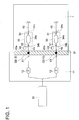
- Fig. 1 is a schematic configuration diagram representing connection between a microreactor, micro-pump and driving solution tank in a first embodiment of the present invention.
- the chip-like microreactor 1 and chip-like micro-pump unit 11 are overlapped with each other at the pump connection section 31 (hatched portion).
- the flow path of the microreactor 1 shown in the drawing refers to only the portion on the periphery of the reagent storage section 33 and the upstream side thereof.
- the reagent storage section 33 is provided with a storage chamber 34a where reagent is stored.
- the inlet 34b of the driving solution and the outlet 34c of the reagent are arranged on the upstream side and the downstream side from the storage chamber 34a respectively.
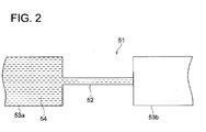
- the inlet 34b and outlet 34c are provided with a water-repellent valve 51.
- the water-repellent valve 51 has the structure shown in Fig. 2 .
- the water-repellent valve 51 is equipped with a liquid feed controlling flow passage 52.
- the liquid feed controlling flow passage 52 has a minute flow path whose cross sectional area (area of the cross section perpendicular to the flow path) is smaller than those of the flow path 53a on the upstream side and the flow path 53b on the downstream side.
- the difference of surface tension between the liquid 54 and the wall of the flow passage controls passage of the solution 54 in contact with the liquid feed controlling flow passage 52 to the flow path 53b.
- the liquid feed pressure above a predetermined level needs to be applied by the micro-pump. This pressure, against the surface tension, pushes the solution 54 through the liquid feed controlling flow passage 52 onto the flow path 53b on the downstream side. After the solution 54 has once flown out to the flow path 53b, the solution flows to the flow path 53b on the downstream side even if the liquid feed pressure enough for pushing the leading edge of the solution 54 toward the flow path 53b onto the downstream side is decreased.
- the passage of solution beyond the liquid feed controlling flow passage 52 is blocked unless the liquid feed pressure in the positive direction from upstream to downstream is equal to or higher than a predetermined level, and when the applied liquid feed pressure exceeds the predetermined level, the solution 54 is allowed to pass through the liquid feed controlling flow passage 52.
- the flow passage wall is made of a hydrophilic material such as glass
- at least the inner surface of the liquid feed controlling flow passage 52 must be provided with water-repellent coating, as exemplified by fluorine-based coating.
- the liquid feed controlling flow passage 52 is produced to have the dimensions of about 25 ⁇ m x 25 ⁇ m with respect to the flow path 53a and flow path 53b having the dimensions of 150 ⁇ m x 300 ⁇ m.
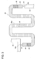
- Fig. 3 is a diagram showing a reagent storage section in the first embodiment of the present invention.
- the oily solution 48 in contact with the aqueous reagent 47 at the interfacial boundary and aqueous solution 49 in contact with the oily solution 48 on the interfacial boundary are contained in each of the inlet 34b and outlet 34c of the reagent storage section 33 in that order.
- the aqueous solution 49 stored on the most upstream side and on the most downstream side of the reagent storage section 33 are kept in contact with the water-repellent valve 51 so as to prevent the leading edge thereof from flowing into the flow path ahead of them.
- the flow path wall is made of a hydrophobic material such as plastic resin, and the aqueous solution 49 in contact with the water-repellent valve 51 is prevented from flowing out of the storage chamber 34a by the difference of surface tension between the solution and the flow path wall.
- the upstream side of the reagent storage section 33 communicates with a micro-pump 12 at the pump connection section 31 of the microreactor 1.
- the liquid feed pressure applied by the micro-pump 12 needs to be equal to or higher than a predetermined pressure is, and this pressure pushes, against the surface tension, the aqueous solution 49 of Fig. 3 through the water-repellent valve 51 of the outlet 34c onto the reagent feed-out flow path 43.
- the solution stored in the reagent storage section 33 follows, even if the liquid feed pressure enough for pushing the leading edge of the aqueous solution 49 beyond the water-repellent valve 51 is decreased.
- the oily solution 48 of Fig. 3 is used to prevent the aqueous reagent 47 from transpiring (and loss by leakage, entry of bubbles, contamination and denaturation) while the micro actuator is kept in storage and it corresponds to the aforementioned sealant.
- the oily solution 48 that can be used for this purpose includes the solution that is solidified under the cold storage conditions when the micro-pump is kept in storage and is melted down into fluid state when the microreactor is placed in the environment of room temperature. This can be exemplified by oils and fats having water solubility of equal to or less than 1 %, as described above.
- the reagent storage section 33 may has a shape of a wide liquid reservoir, in addition to the shape of a slender flow path in Fig. 3 .
- the reagent storage section 33 can be provided with liquid reservoir type reservoir sections where the oily solution 48 and aqueous solution 49 are separately stored.
- an opening 32 is provided on the upstream side from the inlet 34b of the reagent storage section 33. This opening 32 communicates with the inlet 34b of the reagent storage section 33 through the flow path 45. It opens out of one side of the chip.
- micro-pumps 12 are formed on the chip-shaped micro-pump unit 11 by microfabrication technology.
- an opening 15 is formed on the downstream side from the micro-pump 12. This opening 15 communicates with the micro-pump 12 through the flow path and opens out of one side of the chip.
- the opening 32 of the microreactor 1 and the opening 15 of micro-pump unit 11 are positioned and are placed one on top of the other, whereby the microreactor 1 is connected with the micro-pump unit 11 while the micro-pump 12 communicates with the reagent storage section 33.
- the micro-pump unit 11 is connected with the accommodation section 61 on the upstream side, and the driving solution from the driving solution tank 61 is supplied to each micro-pump 12.
- the driving solution is led from the opening 32 to the microreactor 1 by the drive of the micro-pump 12 and is supplied into the storage chamber 34a of the reagent storage section 33 from the inlet 34b through the flow path 45.
- the reagent sealed inside the storage chamber 34a is pushed out of the outlet 34c and is further fed to the reagent feed-out flow path 43.
- a branch flow path 45a branching off from the inlet 34b is arranged in the flow path 45 between the opening 32 and inlet 34b of the microreactor in Fig. 1 .
- An air evacuation flow path 46 is provided on this branch flow path 45a.
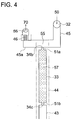
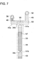
- Fig. 4 is a diagram representing the structure of an air evacuation flow path arranged on the upstream side from the reagent storage section and flow paths provided on the periphery thereof in a first embodiment of the present invention.
- Fig. 5 is an enlarged view of the air evacuation flow path. As illustrated, the branch flow path 45a branched off from the branch section 55 of the inlet 34b is provided through the flow path 45 which runs to the reagent storage section 33 from the opening 32 communicating with the micro-pump.
- the branch flow path 45a is provided with the air evacuation flow path 46 whose end is open to the outside.
- the air evacuation flow path 46 is a flow path of small diameter extending from the flow path wall of the branch flow path 45a. For example, arrangement is made in such a way that a plurality of paths extend from the side of the branch flow path 45a, as shown in Fig. 5 .
- the air evacuation flow path 46 may be arranged at the end of the branch flow path 45a, and the number of the air evacuation flow paths 46 may be one or more than two depending on cases.
- the air evacuation flow path 46 preferably has a diameter of 15 ⁇ m or less, and contact angle with water on the inner surface of the flow path is 30° or more.
- the diameter of the flow path denotes the length of either the longitudinal or lateral side of the rectangular, and preferably the length of both the longitudinal and lateral sides.
- the opening 56 that is open on one side of the chip (upper Side of the paper in Fig. 5 ) for communication with atmosphere is arranged beyond the ends of a plurality of the air evacuation flow paths 46. The air bubbles coming out of the air evacuation flow path 46 are released into the atmosphere through the opening 56.
- Fig. 4 representing the status prior to the driving solution being fed out
- the space between the water-repellent valves 51a and 51b on both ends of the reagent storage section 33 is filled with reagent 57.
- the flow path 45 is filled with air and does not contain liquid.
- the driving solution is fed from the opening 32 into the flow path 45 by a micro-pump (not illustrated). Then the branch flow path 45a branched off from the branch section 55 is filled with the driving solution 50, as shown in Fig. 6 . In this case, air present in the flow path 45 and branch flow path 45a is released to the outside through the air evacuation flow path 46.
- the driving solution 50 starts to flow in the evacuation flow path 46.
- This causes a great increase in the flow path resistance of the air evacuation flow path 46, and the liquid feed pressure of the micro-pump gives a heavy effect to reagent through the driving solution 50.
- the liquid feed pressure is higher than the liquid holding force applied to the water-repellent valve 51b on the downstream side from the reagent storage section 33.
- This arrangement ensures the reagent 57 to be pushed out of the reagent storage section 33 by the driving solution 50, as shown in Fig. 7 .
- the reagent 57 passes through the water-repellent valve 51b and is fed out into the reagent feed-out flow path 43 on the downstream side thereof.
- the water-repellent valve 51a arrangement on the upstream side from the reagent storage section 33 and the water-repellent valve 51b arrangement on the downstream side from the reagent storage section 33 each have a function of holding the reagent 57 filled therein. Further, the water-repellent valve 51b has the function of feeding out the reagent 57 downstream, namely, the role of controlling the liquid feed when the pressure in excess of a predetermined level is applied to the solution.
- the flow path resistance when the solution flows through the air evacuation flow path is configured to be greater than the flow path resistance when the solution flows through the flow channel starting from the branch section and including from the reagent storage section to the reagent feed-out flow path.
- This flow path resistance is preferably increased more than ten times, more preferably increased more than thirty times.
- the leakage of the driving solution into the air evacuation flow path is smaller, the reagent liquid feed accuracy will be higher. If the flow path resistance of the air evacuation flow path is ten times or higher than the flow path resistance of the flow cannel including from the reagent storage section to the reagent feed-out flow path 43, the leakage of the driving solution does not exceed 10 percent of the total liquid feed.
- the microreactor is configured so that the flow path resistance when the driving solution 50 flows into the air evacuation flow path 46 is ten times or more than the flow path resistance when the solution flows through the flow channel 44 starting from the branch section 55 and including from the reagent storage section 33 to the reagent feed-out flow path 43.
- Aqueous driving solution is preferably used as the driving solution. If the viscosity thereof is almost the same, the flow path resistance when the aqueous solution flows through the air evacuation flow path is almost the same independent of types of solution.
- the flow path resistance when the air flows through the air evacuation flow path is preferably lower than the flow path resistance of the flow channel when the solution flows therethrough, where the flow channel starts from the branch section and includes from the reagent storage section to the reagent feed-out flow path.
- the flow path resistance when air flows through the air evacuation flow path 46 is smaller than the flow path resistance when the solution flows through the flow channel starting from the branch section and including from the reagent storage section 33 to the reagent feed-out flow path 43, as shown in Figs. 4 , 6 and 7 .
- the flow path resistance R can be expressed by the following Formula when the flow path is sufficiently slender and the laminar flow is dominant, as in the microreactor of the present invention.
- R ⁇ 32 x ⁇ / S x ⁇ 2 dL
- ⁇ the viscosity of the fluid
- S the cross-sectional area of the flow path
- ⁇ the equivalent diameter of the flow path
- L the length of the flow path.
- ⁇ a x b / a + b / 2 wherein "a" is flow path width "b" is height.
- the flow path resistance for air flowing through the air evacuation flow path is different from that for the driving solution flowing therethrough.
- the viscosity of air at 25 °C is about 0.018 mPa-s.
- the viscosity of the driving solution is about the same as that of water, the viscosity is about 0.89 mPa ⁇ s at 25 °C.
- the flow path resistance when the driving solution 50 flows through the air evacuation flow path 46 is sufficiently higher than that when the liquid flows through the flow path 44.
- control can be provided to minimize the amount of the driving solution 50 leaking out through the air evacuation flow path 46 after air has been removed through the air evacuation flow path 46.
- the step of removing air ensures high-precision control of the timing of mixing a solution such as reagent, mixing ratio of solutions, and liquid feed pressure on the downstream side from the reagent feed-out flow path 43.
- a high degree of accuracy in the micro-structure of the air evacuation flow path 46 is essential to ensure complete prevention of the driving solution 50 leaking from the air evacuation flow path 46. Further, it is necessary to select a material of sufficient water repellency. However, in the present invention, a trace quantity of driving solution 50 is allowed to leak through the air evacuation flow path 46. This arrangement does not required a high degree of accuracy in the micro-structure, further, there is little restriction in the selection of material.
- the flow path resistance when air flows through the air evacuation flow path 46 is smaller than that when the solution flows through the flow path 44.
- the driving solution 50 is preferably fed so that the following Formula is satisfied by the flow rate Q of the driving solution 50 flowing from the opening 32 into the branch section 55 under the micro-pump control: P / R L ⁇ Q ⁇ P / R A wherein P is the pressure at which the water-repellent valve 51b allows passage of reagent 57; R A is the flow path resistance when air flows through the air evacuation flow path 46; and R L is the flow path resistance when the driving solution 50 flows through the air evacuation flow path 46.
- the aforementioned pressure P corresponds to the pressure at which the water-repellent valve 51b allows passage of the aqueous solution 49.
- the flow rate of the driving solution 50 is set at Q ⁇ P / R A in the initial phase of feeding the driving solution 50 into the reagent storage section 33.
- the driving solution 50 flows into the branch flow path 45a, without pushing out the reagent 57 beyond the water-repellent valve 51b of the outlet 34c of the reagent storage section 33, and fills the branch flow path 45a while removing air from the air evacuation flow path 46.
- the flow rate of the driving solution 50 is set at P / P L ⁇ Q.
- the water-repellent valve 51b is applied the liquid pressure in excess of the pressure for allowing the solution to be held.
- the reagent 57 can be pushed out into the reagent feed-out flow path 43 beyond the water-repellent valve 51b by the driving solution 50.
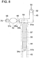
- Fig. 8 is a diagram representing the structure of an air evacuation flow path arranged on the upstream side from the reagent storage section and flow paths provided on the periphery thereof in the second embodiment of the present invention.
- Fig. 9 is a diagram showing how the driving solution enters the air evacuation flow path.
- the components corresponding to those of Figs. 4 through 7 are assigned with the same reference numerals and the detailed description will be omitted to avoid duplication.
- a reservoir section 42 for storing the driving solution 50 fed out through the air evacuation flow path 46 is provided on the outlet side of the air evacuation flow path 46.
- the reservoir section 42 has an enough capacity to store all the volume of the driving solution 50 leaking through the air evacuation flow path 46 until at least the required volume of reagent is fed out into the flow path downstream of the reagent storage section 33.
- the reservoir section 42 is formed in a wide liquid reservoir type structure, for example.
- the reservoir section 42 is installed as aforementioned. This structure ensures that the driving solution 50 leaking out through the air evacuation flow path 46 can be stored in the reservoir section 42, as shown in Fig. 9 . This prevents leakage of the driving solution 50 outside the chip or movement of the driving solution 50 into an unwanted portion.
- a water-repellent valve 51c is arranged between the reservoir section 42 and an opening 56 whose end is open to the atmosphere for communication with the atmosphere and which also communicates with the reservoir section 42.
- This water-repellent valve 51c provides a communication between the reservoir section 42 and a flow path on the side of the opening 56.
- This water-repellent valve 51c is equipped with a liquid feed controlling flow passage (52 in Fig. 2 ) to block off the passage of the driving solution 50 to the opening 56 unless the liquid pressure of the driving solution 50 exceeds a predetermined level of pressure.
- the installation of the water-repellent valve 51c ensures that the air evacuated through the air evacuation flow path 46 escapes to the outside through the opening 56, and prevents the driving solution 50 from leaking out of the reservoir section 42 through the opening 56.
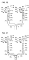
- Fig. 10 is a diagram showing the structure of the flow path upstream of the reagent feed-out flow path in another embodiment of the present invention.
- Fig. 11 is a diagram showing how the reagent is fed out downstream by the driving solution.
- the components corresponding to those of Figs. 4 through 9 are assigned with the same reference numerals, and detailed description will be omitted to avoid duplication.
- the present embodiment is in a form suitable form for the cases where a plurality of reagents are mixed, and the mixed reagent is then reacted with a sample.
- the flow path system shown in the aforementioned embodiment is provided on the upstream and downstream sides of the reagent storage chambers 33 containing different reagents.
- a flow path 45 communicating with the opening 32 for supplying the driving solution 50 is provided on the upstream side from the reagent storage chambers 33 containing reagents 57a or 57b.
- the branch flow path 45a branched off from the storage chamber 34a is provided with air evacuation flow paths 46a or 46b.
- reagent feed-out flow paths 43a or 43b is arranged beyond the outlet 34c.
- the ends of the reagent feed-out flow paths 43a and 43b are equipped with a junction 41 where the flows of reagents 57a and 57b combine with each other. Reagents 57a and 57b are mixed in the flow path beyond the junction 41.
- the mixing ratio between the reagents 57a and 57b can be adjusted by the flow path diameter of the reagent feed-out flow paths 43a and 43b.
- the reagents 57a and 57b are mixed at a volume ratio of one to two.
- the driving solution 50 is fed out by a separately installed micro-pump and reagents 57a and 57b are pushed out downstream.
- the voltage of each micro-pump must be controlled so that liquid feed balance is kept at a constant level at all times, for the purpose of achieving high-precision mixing of the reagents 57a and 57b at a predetermined ratio.
- such voltage control is complex.
- the ratio R a1 /R b1 of the flow path resistance R a1 when the driving solution 50 flows through the air evacuation flow path 46a to the flow path resistance R b1 when the driving solution 50 flows through the air evacuation flow path 46b is approximately equal to the ratio R a2 /R b2 of the flow path resistance R a2 when solution flows through the flow channel 44b starting from the branch section 55 and including from the reagent storage section 33 to the reagent feed-out flow path 43a to the flow path resistance R b2 when the driving solution 50 flows through the flow channel 44a starting from the branch section 55 and including from the reagent storage section 33 to the reagent feed-out flow path 43a.
- This arrangement ensures that the ratio of the volume of the driving solution 50 leaking out from the air evacuation flow path 46a to the volume of the reagent 57a flowing into the junction 41 is approximately equal to the ratio of the volume of the driving solution 50 leaking out though the air evacuation flow path 46b to the volume of the reagent 57b flowing into the junction 41.
- This arrangement provides easy control of the micro-pump as an external pump. To put it another way, this arrangement permits simplified, e.g., unified voltage control of micro-pumps for pushing out reagents by the feed-out operation of the driving solution. This does not involve complicated control of each of the micro-pumps for the purpose of ensuring constant mixing ratio of the reagents.
- Fig. 12 is a plan view showing another embodiment of the microreactor of the present invention.
- three types of reagents are stored in each of the flow path-shaped reagent storage chambers 33a, 33b and 33c.
- the water-repellent valves of the structure illustrated in Fig. 2 are installed on both ends (the inlet 34b on the upstream side and inlet 34c on the downstream side from the reagent storage section 33a) of each reagent storage section. Reagents are sealed in the flow paths between these water-repellent valves.
- the water-repellent valves 1 of Fig. 12 are installed at positions in addition to both ends of the reagent storage chambers 33a, 33b and 33c, although detailed description is omitted.
- the water repellent valves shown in Fig. 2 are provided at the inlet for the mixed reagent and the inlet for the sample both at the junction 38. These water-repellent valves control the timing of starting the liquid feed to the flow path located beyond the valves.
- the openings 32c through 32e that are open outward on one side of the microreactor 1 are provided on the upstream side from the reagent storage chambers 33a, 33b and 33c in Fig. 12 .
- these openings 32c through 32e are made to communicate with the micro-pumps to be positioned with respect to the openings of the flow paths provided on the connection surface of the micro-pump unit.
- the flow paths between the reagent storage chambers 33a through 33c and openings 32c through 32e are designed to have a structure illustrated in Fig. 4 , whereby air between the driving liquid and the reagent is removed from the air evacuation flow path.
- the openings 32a, 32b and 32f through 32k are made to communicate with the micro-pumps by connecting the microreactor 1 to the micro-pump unit.
- the pump connection section (reference numeral 31 of Fig. 1 ) is formed by the chip surface including the openings 32a through 32k. The pump connection section is brought in close contact with the connection surface of the micro-pump unit, whereby the microreactor 1 is connected to the micro-pump unit.
- the contact surface of this pump connection section is preferably formed of a flexible (elastic or shape-following) resin such as polytetrafluoroethylene and silicone resin.
- a flexible contact surface can be made of the constituent material of the microreactor, or a separate flexible member laminated around the flow path opening in the pump connection section.
- the reagents stored in the reagent storage chambers 33a, 33b and 33c are fed through the water-repellent valve (not illustrated) installed on the ends on the downstream side from the reagent storage chambers 33a, 33b and 33c, by the separately installed micro-pumps communicating with the openings 32c through 32e.
- the reagents then flow into the junction 41 from the reagent feed-out flow paths 43a through 43c.
- three types of reagents are mixed in the reagent mixing flow path 35 which runs beyond the junction 41.
- the mixed reagent having been mixed in the reagent mixing flow path 35 and fed out into the mixed reagent feed-out flow path 36 merges with the sample stored in a sample reception section 37 at the junction 38.
- the mixed reagent is pushed out downstream by the driving solution through the micro-pump communicating with the opening 32b.
- the sample is pushed out downstream by the driving solution through the micro-pump communicating with the opening 32a.
- the mixture made of the mixed reagent and sample is stored in a reaction section 39, and reaction is started by heating.
- the solution is fed into the detection section 40, and a target substance is detected, for example, by the optical detection method.
- a target substance is detected, for example, by the optical detection method.
- Each reagent stored in advance in the flow path beyond the openings 32f through 32j e.g., solution for stopping the reaction between the mixed reagent and sample, solution for executing the required processing such as labeling for the target substance, and cleaning solution
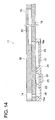
- Fig. 13 is a perspective view representing a micro-pump. unit used for the microreactor of Fig. 12 .
- Fig. 14 is a cross sectional view thereof.
- the micro-pump unit 11 is made up of three substrates: a silicon substrate 17; a glass substrate 18 provided thereon; and a glass substrate 19 thereon.
- the substrates 17 and 18 are connected to the substrates 18 and 19 by anodic bonding respectively.
- the micro-pump 12 (piezo-pump) is comprised of the internal space between the silicon substrate 17 and glass substrate 18 laminated thereon by anodic bonding.
- the substrate 17 is the silicon wafer formed into a predetermined shape by photolithographic technique.
- the pressure chamber 22, first flow path 23, second flow path 24, first liquid chamber 25, and second liquid chamber 26 are formed by microfabrication including forming an oxide film on the silicon substrate surface, coating of a resist, exposure and development of the resist, etching of the oxide film, and etching silicon by the ICP (Inductively Coupled Plasma).
- ICP Inductively Coupled Plasma
- the silicon substrate is processed into a diaphragm.
- a piezoelectric element 21 made of lead zirconate titanate (PZT) is laminated on the outer surface thereof.
- This micro-pump 12 is driven as follows by the control voltage applied to the piezoelectric element 21.
- the piezoelectric element 21 is oscillated by the applied voltage of a predetermined waveform, and the silicon diaphragm at the position of the pressure chamber 22 is oscillated, whereby the volume of the pressure chamber 22 is increased and decreased.
- the first flow path 23 and second flow path 24 are the same in width and depth.
- the length of the second flow path 24 is longer than that of the first flow path 23.
- the second flow path 24 has a longer flow path length, so that the increased differential pressure easily causes a laminar flow.
- the percentage of change in the flow path resistance with respect to a change in the differential pressure is smaller than that of the first flow path 23.
- the driving solution is fed in the positive direction from left to right in Fig. 14 .
- the driving solution is fed in the negative direction from right to left in Fig. 14 .
- the difference between the percentages of changes in flow path resistances relative to the change in differential pressure in the first flow path 23 and second flow path 24 is not necessarily caused by the difference in the length of the flow path. It may be caused by other geometric differences.
- the flow rate by the micro-pump 12 can be controlled by adjusting the voltage applied to the piezoelectric element 21.
- a flow path 20 is patterned on the substrate 19.
- the flow path 20 is formed in a rectangular structure having a rectangular cross-sectional shape with a width of about 150 ⁇ m and a depth of about 300 ⁇ m.
- the upstream side of the flow path 20 leads to the micro-pump 12 through the flow path provided on the substrate 17 via the through-hole 16b in the substrate 18.
- the upstream side of the micro-pump 12 is connected to the opening 14 provided in the glass-made substrate 19 through the flow path of the substrate 17 and the through-hole 16a in the substrate 18.
- This opening 14 is connected with the driving solution tank (not illustrated).
- the opening 14 is connected to the driving solution tank, for example, through the gasket made of PDMS (polydimethyl siloxane).
- the openings 15a, 15b and 15c communicate with the openings 32c, 32d and 32e of the microreactor in Fig. 12 (where only a part of the entire micro-pump unit is shown in Fig. 13 ).
- the driving solution is fed through the flow path 20, opening 15a and opening 32c by the micro-pump 12 so that the reagent stored in the reagent storage section 33a is pushed out downstream.
- the driving solution is fed through the flow path 20, opening 15b and opening 32d so that the reagent stored in the reagent storage section 33b is pushed out downstream.
- the driving solution is fed through the flow path 20, opening 15c and opening 32e, and the reagent stored in the reagent storage section 33c is pushed out downstream.
- micro-pumps for feeding the reagents and other liquids are arranged on a single chip. Then this chip and microreactor are put one on top of another at the time of analysis to provide communication between them.
- the micro-pump unit designed in this structure can be used to produce a compact pump mechanism that pushes the reagent in the microreactor out downstream of the minute flow path.
- a single driving solution tank can be shared by a plurality of micro-pumps, and connection between the driving solution tank and chip-formed micro-pump unit does not require a special piping or a routing chip. This advantage permits construction of a compact pump mechanism that pushes the reagent in the microreactor out downstream of the minute flow path.
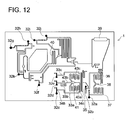
- Fig. 15 is a perspective view showing an example of an integrated micro analysis system.
- Fig. 16 is an internal structure of the system body in the integrated micro analysis system.
- the system body 3 of the integrated micro analysis system contains apparatuses for analysis which are installed in an enclosure-shaped storage member 62.
- the storage member 62 incorporates the micro-pump unit 11, which further incorporates a chip connection section 13 provided with a flow path opening communicating with the microreactor 1, and a plurality of micro-pumps (not illustrated).
- the storage member 62 includes a detection processing apparatus (a light source 68 for detecting reaction in the microreactor 1 such as an LED, photomultiplier and CCD camera, and a detector 69 for optical detection by visible spectroscopy, fluorometry or the like), and a control apparatus for controlling this detection processing apparatus and the micro-pump unit 11.
- This control apparatus provides control of the liquid feed by the micro-pump, control of the detection processing apparatus for detecting reaction in the microreactor 1 by optical means, control of the microreactor 1 temperature by the heating/cooling unit (to be described later), control of the reaction in the microreactor 1, data collection (measurement) and processing.
- the micro-pump is controlled by applying a drive voltage to the micro-pump according to the program containing the settings of the liquid feed sequence, flow rate, timing and other conditions.
- the target substance in the specimen is analyzed in the microreactor 1 after mounting the microreactor 1 inside the storage member 62 in the situation that the pump connection section 31 made up of the openings of the flow paths provided on the upstream side (e.g., on the upstream side from the reagent storage section or sample reception section) of the minute flow paths of the microreactor 1 and the chip surfaces in the periphery of the openings, and the chip connection section 13 of the micro-pump unit 11 are brought into contact with each other under fluid-tight conditions.
- the microreactor 1 is placed on a conveyance tray 65 to be led into the storage member 62 from the insertion port 63.
- a conveyance tray is not necessarily required if the microreactor can be fixed inside the storage member 62 while the microreactor is pressed against the micro-pump unit.
- the storage member 62 incorporates a heating/cooling unit (Peltier element 66 and heater 67) for locally heating and cooling the microreactor 1 mounted at a predetermined position.
- a heating/cooling unit Peltier element 66 and heater 67
- selective cooling of the reagent storage section is achieved by the Peltier element 66 pressed against the region of the reagent storage section of the microreactor 1, whereby degeneration of the reagent is prevented.
- the heater 67 is pressed against the region of the flow path constituting the reaction section, whereby the reaction section is selectively heated and the temperature of the reaction section is adjusted to the level appropriate for reaction.
- the micro-pump unit 11 is connected to the driving solution tank 61, and the upstream side of the micro-pump Communicates with this driving solution tank 61. In the meantime, the downstream side of the micro-pump communicates with the opening of the flow path arranged on one surface of the micro-pump unit 11.
- the microreactor 1 is connected to the micro-pump unit 11 in such a way that each of the openings of the flow path connected to each of the micro-pumps communicates with each of the openings of the flow path arranged on the pump connection section 31 of the microreactor 1.
- the aqueous driving solution stored in the driving solution tank 61 is fed into the storage section for each liquid in the microreactor 1 through the pump connection section 31 by the micro-pump, and the liquid of each storage section is pushed out downstream of the microreactor 1 by the driving solution.
- a series of operations including pre-processing, reaction and detection of the specimen as a test sample is carried out when the microreactor 1 is being mounted on the system body 2 composed of the integration of the micro-pump, detection processing apparatus and control apparatus.
- a predetermined reaction and optical measurement in response to feeding, pre-processing and mixing of the sample and reagent are automatically performed as a series of continuous steps, and the test data together with the required conditions and record items is stored in a file.
- the analysis result is indicated on the display 64 of the storage member 62.
- a single chip includes:
- the aforementioned micro-pump unit is connected to this micro-reactor through the pump connection section.
- the specimen or biological substance e.g., DNA and other biological substance
- the specimen or biological substance extracted from the specimen placed in the sample reception section, and the reagent contained in the reagent storage section are fed into the downstream flow path. They are mixed and are made to react in the reaction section of the minute flow path, for example, in the reaction section for gene amplification reaction (antigen-antibody reaction in the case of protein).
- the processed solution obtained by processing this reaction solution and the probe contained in the probe storage section are fed into the detection section along the downstream flow path. They are then mixed in the flow path and are made to couple (hybridize) with the probe.
- detection of a biological substance is carried out based on this reaction product.
- the positive control contained in the positive control storage section and negative control contained in the negative control storage section are also subjected to the aforementioned reaction and detection.
- the specimen injected into the sample reception section is pre-processed in advance, for example, by mixing the specimen and processing solution in the specimen pre-processing section provided in the flow path, prior to mixture with the reagent, as required.
- This specimen pre-processing section may include a separation filter, adsorption resin or beads.
- Preferred specimen pre-processing is exemplified by separation or concentration of the analyte, and deproteinization.
- processing of bacteriolysis/DNA extraction is carried out using a bacteriolytic agent such as a 1% SDS mixture.
- a bacteriolytic agent such as a 1% SDS mixture.
- DNA is released out of the cell, and is adsorbed onto the beads or filter film surface.
- a predetermined volume of required reagent is sealed in the reagent storage section of the microreactor in advance. This eliminates the need of filling with a predetermined volume of the reagent every time it is used.
- the reagent is ready for use at any time.
- the reagents required for measurement are commonly known.
- the reagent containing the antibody corresponding thereto preferably the reagent containing a monoclonal antibody is used.
- the antibody is preferably labeled by a biotin or FITC.
- the examples of the reagents stored in advance in the microreactor for genetic screening include probes used for detection, color development reagents and pre-processing reagents for the aforementioned specimen pre-processing in addition to various types of reagents used for gene amplification.
- the reagents are pushed out of each reagent storage section, and that the merged reagents make a mixed reagent.
- the driving solution is supplied from the micro-pump, whereby the specimen is pushed out of the sample reception section. They are merged with the mixed reagent with stabilized mixing ratio, whereby the reaction section starts reaction required for analysis such as gene amplification reaction, analyte trapping or antigen-antibody reaction.
- the flow path between the inlet of the sample reception section in the microreactor and the opening of the pump connection section is provided with the aforementioned air evacuation flow path.
- the flow path of the microreactor is made of a hydrophobic resin, and reagent is pushed out by the aqueous driving solution such as pure water or buffer solution.
- the air evacuation flow path whose outwardly opening end has a diameter of several ⁇ m, the air bubbles between these solutions are removed, in the initial phase of feeding out the driving solution into the inlet after the micro-pump unit is connected to the microreactor.
- the PCR amplification method can be used as a DNA amplification method.
- This PCR amplification method together with improvements, is described in various documents, and is actively employed over an extensive range.
- the PCR amplification method requires control of temperature wherein the control is made among three different temperatures.
- a flow path device capable of temperature control appropriate for micro-chips has already been proposed by the present inventors (Unexamined Japanese Patent Application Publication No. 2004-108285 ).
- This device system can be used in the amplification flow path of the chip of the present invention. This allows the heat cycle to be switched at a high speed. BEcause the minute flow path is made to be a micro-reaction cell having a small heat capacity, the DNA amplification method requires much shorter time than the conventional manual operation method.
- the ICAN (Isothermal Chimera Primer Initiated Nucleic Acid Amplification) method developed in recent years carries out the DNA amplification in a short period of time at any temperature between 50 through 65 °C (Japanese Registration Patent No. 3433929 ), and is an amplification technology suitable for use in the system of the present invention.
- the work requiring one hour in the manual operation method can be completed in the system of the present invention in 10 through 20 minutes, preferably in 15 minutes, wherein analysis is also included in the work completed in such a short time.
- the downstream portion from the reaction section in the minute flow path of the microreactor is provided with a detection section for screening an analyte, for example, an amplified gene.
- a detection section for screening an analyte, for example, an amplified gene.
- At least the detection portion is made of a transparent material, preferably a transparent plastic for the purpose of performing optical measurement.
- the protein having an affinity for biotin (avidin or streptoavidin) adsorbed on the detection section on the minute flow path is connected specifically with the biotin labeled on a probe substance or the biotin labeled on the 5'-terminus of the primer used in gene amplification reaction.
- the probe labeled with the biotin or the amplified gene is trapped by this detection portion.
Landscapes
- Chemical & Material Sciences (AREA)
- Dispersion Chemistry (AREA)
- Engineering & Computer Science (AREA)
- Health & Medical Sciences (AREA)
- General Engineering & Computer Science (AREA)
- Chemical Kinetics & Catalysis (AREA)
- Analytical Chemistry (AREA)
- Clinical Laboratory Science (AREA)
- Hematology (AREA)
- General Health & Medical Sciences (AREA)
- Mechanical Engineering (AREA)
- Organic Chemistry (AREA)
- Automatic Analysis And Handling Materials Therefor (AREA)
- Apparatus Associated With Microorganisms And Enzymes (AREA)
- Physical Or Chemical Processes And Apparatus (AREA)
- Micromachines (AREA)
Claims (8)
- Ein Mikroreaktor (1), umfassend in einen plattenähnlichen Chip:eine Reagenzspeichersektion; wobei die Reagenzspeichersektion beinhaltet:eine Speicherkammer (34a) zum Aufbewahren eines flüssigen Reagenz (57, 57a, 57b) darin;einen Einlass (34b), durch den eine Antriebslösung (50) in die Speicherkammer (34a) injiziert wird; undeinen Auslass (34c), durch den das Reagenz (57, 57a, 57b) durch die injizierte Antriebslösung (50) aus der Speicherkammer (34a) herausgedrückt wird,einen Reagenzien-Ausflusspfad (43, 43a, 43b, 43b), der mit der Reagenzspeichersektion in Verbindung steht und durch den das Reagenz (57, 57a, 57b) aus der Reagenzspeichersektion abgeführt wird;eine Öffnung (32, 32a bis 32k), die mit dem Einlass (34b) der Reagenzspeichersektion über einen Strömungspfad (45, 53a, 53b) in Verbindung steht und konfiguriert ist, um mit einer externen Pumpe zum Zuführen der Antriebslösung (50) zu kommunizieren, wenn die externe Pumpe mit dem Chip verbunden ist;einen Abzweigströmungspfad (45a), der an einem Abzweigabschnitt (55) an einer Position des Einlasses (34b) von dem Strömungspfad (45, 53a, 53b) abgezweigt ist, der die Öffnung (32, 32a bis 32k) mit dem Einlass (34b) verbindet;einen Luftaustrittsströmungspfad (46, 46a, 46b), der in dem Abzweigströmungspfad (45a) vorgesehen ist und dessen distales Ende nach einer Außenseite offen ist,ein wasserabweisendes Ventil (51, 51a, 51b), das am Auslass (34c) des Reagenzspeicherabschnitts vorgesehen ist; undein wasserabweisendes Ventil (51, 51a, 51b), das am Einlass (34b) des Reagenzspeicherabschnitts vorgesehen ist;wobei ein Strömungswiderstand des Luftaustrittsströmungspfades (46, 46a, 46b), wenn eine Flüssigkeit hindurchströmt, größer ist als ein Strömungswiderstand eines Strömungspfads, der vom Abzweigabschnitt (55) als Ausgangspunkt ausgeht und den Abzweigabschnitt (55) zum Reagenzien-Ausflusspfad (43, 43a, 43b) beinhaltet, wenn die Flüssigkeit durch den Strömungspfad strömt, so dass, nachdem die zugeführte Antriebslösung (50) zwischen dem Reagenz (57, 57a, 57b) und der Antriebslösung (50) vorhandene Luft durch den Luftaustrittsströmungspfad (46, 46a, 46b) entfernt hat, und der Abzweigströmungspfad (45a) mit der Antriebslösung (50) gefüllt ist, die Antriebslösung (50) das Reagenz (57, 57a, 57b), welches die Reagenzspeichersektion füllt, hieraus in den Reagenzien-Ausflusspfad (43, 43a, 43b, 43b) herausdrückt, wobei das Einschließen von Luft zwischen der Antriebslösung (50) und dem Reagenz (57, 57a, 57b) nicht zugelassen wird.
- Der Mikroreaktor (1) nach Anspruch 1, wobei ein Strömungswiderstand des Luftaustrittsströmungspfads (46, 46a, 46b), wenn die Flüssigkeit durch ihn strömt, das 10-fache oder höher ist als ein Strömungswiderstand des Strömungspfads, wenn die Flüssigkeit durch ihn strömt, wobei der Strömungspfad vom Abzweigabschnitt (55) als Ausgangspunkt ausgeht und von der Reagenzspeichersektion zum Reagenzien-Ausflusspfad (43, 43a, 43b) beinhaltet.
- Der Mikroreaktor (1) nach Anspruch 1 oder 2, wobei ein Strömungswiderstand des Luftaustrittsströmungspfads (46, 46a, 46b), wenn eine Luft durch ihn strömt, kleiner ist als ein Strömungswiderstand des Strömungspfads, wenn die Flüssigkeit durch ihn strömt, wobei der Strömungspfad vom Abzweigabschnitt (55) als Ausgangspunkt ausgeht und von der Reagenzspeichersektion zum Reagenzien-Ausflusspfad (43, 43a, 43b) beinhaltet.
- Der Mikroreaktor (1) nach einem der Ansprüche 1 bis 3, wobei das wasserabweisende Ventil (51, 51a, 51b), das am Auslass (34c) der Reagenzspeichersektion vorgesehen ist, Folgendes beinhaltet:einen Flüssigkeitszufuhrsteuerungs-Strömungspfad (52), der einen Strömungspfad (45, 53a, 53b) auf einer Seite der Reagenzspeichersektion mit einem Strömungspfad (45, 53a, 53b) auf einer stromabwärts gelegenen Seite des Flüssigkeitszufuhrsteuerungs-Strömungspfads verbindet und eine Querschnittsfläche aufweist, die kleiner als eine Querschnittsfläche dieser Strömungspfade (45, 53a, 53b) ist,wobei das wasserabweisende Ventil (51, 51a, 51b) verhindert, dass ein Reagenz (57, 57a, 57b) hindurchpassiert, es sei denn, ein Flüssigkeitszuführungsdruck erreicht einen vorbestimmten Druck und lässt das Reagenz (57, 57a, 57b) hindurchpassieren, wenn der Flüssigkeitszuführungsdruck gleich oder höher als der vorbestimmte Druck ist, und eine Flussrate Q einer Flüssigkeit, die von der Öffnung (32, 32a bis 32k) in den Abzweigabschnitt (55) strömt, die folgende Beziehung erfüllt:
 P ist ein Druck, bei dem ein Reagenz (57, 57a, 57b, 57b) durch das wasserabweisende Ventil (51, 51a, 51b, 51b) passiert;RA ist ein Strömungswiderstand, wobei eine Luft durch den Luftaustrittsströmungspfad (46, 46a, 46b) strömt; undRL ist ein Strömungswiderstand, bei dem eine Flüssigkeit den Luftaustrittsströmungspfad (46, 46a, 46b) passiert.
 - Der Mikroreaktor (1) nach einem der Ansprüche 1 bis 4, umfassend:eine Vielzahl der Reagenzspeichersektionen;eine Vielzahl der Reagenzien-Ausflusspfade (43, 43a, 43b); undeine Verbindung (35, 38, 41), an der sich jeder der Vielzahl der Reagenzien-Ausflusspfade (43, 43a, 43b) trifft,wobei ein Verhältnis zwischen einem Fluidwiderstand von jedem der Luftaustrittsströmungspfade (46, 46a, 46b, 46b), wenn eine Flüssigkeit durch sie strömt, im Wesentlichen das gleiche ist wie ein Verhältnis zwischen einem Strömungswiderstand jedes der Strömungskanäle, wenn eine Flüssigkeit durch sie strömt, wobei der Strömungspfad vom Abzweigabschnitt (55) als Ausgangspunkt ausgeht und von der Reagenzspeichersektion zum Reagenzien-Ausflusspfad (43, 43a, 43b) beinhaltet.
- Der Mikroreaktor (1) nach einem der Ansprüche 1 bis 5, umfassend:
eine Reservoirsektion (42), die auf einer Ausgangsseite des Luftaustrittsströmungspfades (46, 46a, 46b, 46b) vorgesehen ist und zum Zurückbehalten der Antriebslösung (50), die über den Luftaustrittsströmungspfad (46, 46a, 46b) zugeführt wird, dient. - Der Mikroreaktor (1) nach Anspruch 6, umfassend:eine Öffnung (56), die mit der Reservoirsektion (42) verbunden ist und deren distales Ende nach außen offen ist; undein wasserabweisendes Ventil (51c), das zwischen der Öffnung (56) und der Reservoirsektion vorgesehen ist, wobei das wasserabweisende Ventil (51c) Folgendes beinhaltet:einen Flüssigkeitszufuhrsteuerungs-Strömungspfad, der einen Strömungspfad (45, 53a, 53b) auf einer Seite der Reservoirsektion (42) mit einem Strömungspfad (45, 53a, 53b) auf einer Seite der Öffnung (56) verbindet und eine Querschnittsfläche aufweist, die kleiner ist als eine Querschnittsfläche dieser Strömungspfade (45, 53a, 53b),wobei das wasserabweisende Ventil (51c) die Antriebslösung (50) daran hindert durch eine Seite der Öffnung (56) zu passieren, es sei denn, ein Flüssigkeitsdruck überschreitet einen vorbestimmten Druck.
- Ein Mikroreaktor (1) nach Anspruch 1, wobei die Speicherkammer (34a) mit einem flüssigen Reagenz (57, 57a, 57b) gefüllt ist.
Applications Claiming Priority (2)
| Application Number | Priority Date | Filing Date | Title |
|---|---|---|---|
| JP2005322507 | 2005-11-07 | ||
| PCT/JP2006/320709 WO2007052471A1 (ja) | 2005-11-07 | 2006-10-18 | マイクロリアクタおよびそれを用いた送液方法 |
Publications (3)
| Publication Number | Publication Date |
|---|---|
| EP1946830A1 EP1946830A1 (de) | 2008-07-23 |
| EP1946830A4 EP1946830A4 (de) | 2012-09-19 |
| EP1946830B1 true EP1946830B1 (de) | 2019-04-03 |
Family
ID=38005624
Family Applications (1)
| Application Number | Title | Priority Date | Filing Date |
|---|---|---|---|
| EP06821911.2A Not-in-force EP1946830B1 (de) | 2005-11-07 | 2006-10-18 | Mikroreaktor |
Country Status (4)
| Country | Link |
|---|---|
| US (1) | US8133456B2 (de) |
| EP (1) | EP1946830B1 (de) |
| JP (1) | JP4888394B2 (de) |
| WO (1) | WO2007052471A1 (de) |
Families Citing this family (41)
| Publication number | Priority date | Publication date | Assignee | Title |
|---|---|---|---|---|
| US8030057B2 (en) | 2004-01-26 | 2011-10-04 | President And Fellows Of Harvard College | Fluid delivery system and method |
| EP2523004B1 (de) | 2004-01-26 | 2020-05-20 | President and Fellows of Harvard College | Verfahren zur Bestimmung eines Analyten und Immunoassay |
| JP5305361B2 (ja) | 2007-05-04 | 2013-10-02 | オプコ・ダイアグノスティクス・リミテッド・ライアビリティ・カンパニー | 流体コネクタおよびマイクロ流体システム |
| JP2009053030A (ja) * | 2007-08-27 | 2009-03-12 | Yokogawa Electric Corp | 液体分注装置 |
| JP2009166472A (ja) * | 2007-12-18 | 2009-07-30 | Seiko Epson Corp | 液体供給装置及び液体噴射装置 |
| WO2010080115A2 (en) * | 2008-12-18 | 2010-07-15 | Claros Diagnostics, Inc. | Improved reagent storage in microfluidic systems and related articles and methods |
| DK2391451T3 (en) | 2009-02-02 | 2018-10-15 | Opko Diagnostics Llc | STRUCTURES FOR MANAGING LIGHT INTERACTION WITH MICROFLUIDIC DEVICES |
| EA024999B1 (ru) | 2009-11-24 | 2016-11-30 | Опкоу Дайагностикс, Ллк. | Смешивание и доставка текучих сред в микрофлюидных системах |
| WO2011088247A1 (en) * | 2010-01-13 | 2011-07-21 | Nomadics, Inc. | In situ-dilution method and system for measuring molecular and chemical interactions |
| JP2011163993A (ja) * | 2010-02-12 | 2011-08-25 | Hitachi Ltd | 試料分析チップ及び試料分析システム |
| CA3016967C (en) | 2010-04-16 | 2021-08-31 | Opko Diagnostics, Llc | Systems and devices for analysis of samples |
| USD645971S1 (en) | 2010-05-11 | 2011-09-27 | Claros Diagnostics, Inc. | Sample cassette |
| FR2960452B1 (fr) * | 2010-05-31 | 2017-01-06 | Corning Inc | Dispositif formant microreacteur equipe de moyens de collecte et d'evacuation in situ du gaz forme et procede associe |
| CN105351166B (zh) * | 2010-09-14 | 2017-12-15 | 彭兴跃 | 一种微流路芯片系列微器件的结构 |
| CN103154529B (zh) * | 2010-09-14 | 2016-01-13 | 彭兴跃 | 一种微流路芯片系列微器件的结构 |
| KR101197208B1 (ko) * | 2011-06-29 | 2012-11-02 | 한국과학기술원 | 마이크로 펌프 및 그 구동 방법 |
| US9901924B2 (en) | 2011-07-14 | 2018-02-27 | Enplas Corporation | Fluid handling device, fluid handling method, and fluid handling system |
| WO2013011652A1 (ja) * | 2011-07-20 | 2013-01-24 | 株式会社エンプラス | 流体取扱装置、流体取扱方法および流体取扱システム |
| WO2013029159A1 (en) | 2011-08-30 | 2013-03-07 | The Royal Institution For The Advancement Of Learning / Mcgill University | Method and system for pre-programmed self-power microfluidic circuits |
| US9446403B2 (en) * | 2011-10-24 | 2016-09-20 | Xiamen Xinchuang Biological Technology Co., Ltd. | Micro-channel chip |
| MY193914A (en) | 2012-03-05 | 2022-11-01 | Oy Arctic Partners Ab | Methods and apparatuses for predicting risk of prostate cancer and prostate gland volume |
| US9990464B1 (en) | 2012-10-09 | 2018-06-05 | Pall Corporation | Label-free biomolecular interaction analysis using a rapid analyte dispersion injection method |
| EP2916953B1 (de) * | 2012-11-08 | 2023-03-29 | Takara Bio USA, Inc. | Extraktion von eingeschlossener flüssigkeit aus bohrlöchern |
| EP2969156B1 (de) | 2013-03-13 | 2019-04-10 | Opko Diagnostics, LLC | Mischen von fluiden in fluidiksystemen |
| US9103429B2 (en) * | 2013-06-17 | 2015-08-11 | Deere & Company | Reservoir assembly with breather vent |
| GB201320146D0 (en) | 2013-11-14 | 2014-01-01 | Cambridge Entpr Ltd | Fluidic separation and detection |
| JP6506907B2 (ja) * | 2014-02-10 | 2019-04-24 | 株式会社エンプラス | 液体取扱装置 |
| JP6281945B2 (ja) * | 2014-03-11 | 2018-02-21 | 国立研究開発法人産業技術総合研究所 | 多孔質媒体を利用したアッセイ装置 |
| KR102587637B1 (ko) | 2014-12-12 | 2023-10-10 | 옵코 다이어그노스틱스, 엘엘씨 | 성형에 의해 제조되는 유체 시스템을 비롯한, 항온 처리 채널을 포함하는 유체 시스템 |
| USD804682S1 (en) | 2015-08-10 | 2017-12-05 | Opko Diagnostics, Llc | Multi-layered sample cassette |
| US10852310B2 (en) | 2015-12-11 | 2020-12-01 | Opko Diagnostics, Llc | Fluidic systems involving incubation of samples and/or reagents |
| JP6433473B2 (ja) * | 2016-11-04 | 2018-12-05 | シスメックス株式会社 | 液体封入カートリッジ、液体封入カートリッジの製造方法および送液方法 |
| KR102614682B1 (ko) * | 2017-12-11 | 2023-12-19 | 덴카 주식회사 | 액체 시료 검사 키트용 막 담체, 액체 시료 검사 키트, 액체 시료 검사 키트의 제조 방법, 액체 시료의 검사 방법 및 막 담체 |
| JP2019190977A (ja) * | 2018-04-25 | 2019-10-31 | 株式会社バイオデバイステクノロジー | マイクロチップおよびマイクロチップ測定システムおよび測定方法 |
| KR101996617B1 (ko) * | 2018-10-11 | 2019-07-04 | 주식회사 엘지화학 | 일체형 카트리지 |
| JP7245242B2 (ja) * | 2019-04-22 | 2023-03-23 | 積水化学工業株式会社 | チップ及び流体の合流方法 |
| CN110308296B (zh) * | 2019-07-10 | 2025-01-28 | 深圳金迈隆电子技术有限公司 | 一种片上实验室 |
| JP7524866B2 (ja) * | 2020-09-07 | 2024-07-30 | 株式会社島津製作所 | 試験装置、圧入方法および、マイクロ流路デバイス |
| JP7577301B2 (ja) * | 2020-09-23 | 2024-11-05 | 株式会社Provigate | 液体試料処理装置 |
| WO2023083257A1 (zh) * | 2021-11-12 | 2023-05-19 | 迈安纳(上海)仪器科技有限公司 | 一种微流控芯片盒及其微流控设备 |
| WO2025156292A1 (zh) * | 2024-01-26 | 2025-07-31 | 深圳华大生命科学研究院 | 液体注入装置、液体注入方法和微流控系统 |
Citations (1)
| Publication number | Priority date | Publication date | Assignee | Title |
|---|---|---|---|---|
| WO2002083310A2 (en) * | 2001-04-13 | 2002-10-24 | Nanostream, Inc. | Microfluidic metering systems and methods |
Family Cites Families (16)
| Publication number | Priority date | Publication date | Assignee | Title |
|---|---|---|---|---|
| US6001307A (en) * | 1996-04-26 | 1999-12-14 | Kyoto Daiichi Kagaku Co., Ltd. | Device for analyzing a sample |
| WO1998053311A2 (en) * | 1997-05-23 | 1998-11-26 | Gamera Bioscience Corporation | Devices and methods for using centripetal acceleration to drive fluid movement in a microfluidics system |
| ATE362532T1 (de) | 1999-03-19 | 2007-06-15 | Takara Bio Inc | Verfahren zur amplifizierung einer nukleinsäuresequenz unter verwendung eines chimären primers |
| JP3629405B2 (ja) | 2000-05-16 | 2005-03-16 | コニカミノルタホールディングス株式会社 | マイクロポンプ |
| JP2002102681A (ja) | 2000-09-28 | 2002-04-09 | Kawamura Inst Of Chem Res | 加熱脱気機構を有する微小ケミカルデバイス |
| JP2002221485A (ja) | 2000-11-22 | 2002-08-09 | Minolta Co Ltd | マイクロチップ |
| JP2002236131A (ja) * | 2000-12-08 | 2002-08-23 | Minolta Co Ltd | マイクロチップ |
| JP4148778B2 (ja) * | 2001-03-09 | 2008-09-10 | バイオミクロ システムズ インコーポレイティッド | アレイとのミクロ流体的インターフェース機器 |
| JP4106977B2 (ja) | 2002-06-21 | 2008-06-25 | 株式会社日立製作所 | 分析チップ及び分析装置 |
| JP2004061320A (ja) | 2002-07-29 | 2004-02-26 | Kawamura Inst Of Chem Res | マイクロ流体デバイスの送液方法 |
| JP3725109B2 (ja) | 2002-09-19 | 2005-12-07 | 財団法人生産技術研究奨励会 | マイクロ流体デバイス |
| DE10302721A1 (de) * | 2003-01-23 | 2004-08-05 | Steag Microparts Gmbh | Mikrofluidische Anordnung zum Dosieren von Flüssigkeiten |
| JP3988658B2 (ja) | 2003-03-07 | 2007-10-10 | コニカミノルタホールディングス株式会社 | マイクロポンプの制御方法およびマイクロ流体システム |
| DE102004007567A1 (de) * | 2004-02-17 | 2005-09-01 | Boehringer Ingelheim Microparts Gmbh | Mikrostrukturierte Plattform und Verfahren zum Handhaben einer Flüssigkeit |
| JP4145280B2 (ja) | 2004-02-27 | 2008-09-03 | 富士フイルム株式会社 | 発光素子 |
| JP4784508B2 (ja) | 2004-05-07 | 2011-10-05 | コニカミノルタエムジー株式会社 | 検査用マイクロリアクタおよび検査装置ならびに検査方法 |
-
2006
- 2006-10-18 EP EP06821911.2A patent/EP1946830B1/de not_active Not-in-force
- 2006-10-18 US US12/092,116 patent/US8133456B2/en not_active Expired - Fee Related
- 2006-10-18 WO PCT/JP2006/320709 patent/WO2007052471A1/ja not_active Ceased
- 2006-10-18 JP JP2007542325A patent/JP4888394B2/ja not_active Expired - Fee Related
Patent Citations (1)
| Publication number | Priority date | Publication date | Assignee | Title |
|---|---|---|---|---|
| WO2002083310A2 (en) * | 2001-04-13 | 2002-10-24 | Nanostream, Inc. | Microfluidic metering systems and methods |
Also Published As
| Publication number | Publication date |
|---|---|
| JP4888394B2 (ja) | 2012-02-29 |
| US20090155927A1 (en) | 2009-06-18 |
| US8133456B2 (en) | 2012-03-13 |
| JPWO2007052471A1 (ja) | 2009-04-30 |
| WO2007052471A1 (ja) | 2007-05-10 |
| EP1946830A4 (de) | 2012-09-19 |
| EP1946830A1 (de) | 2008-07-23 |
Similar Documents
| Publication | Publication Date | Title |
|---|---|---|
| EP1946830B1 (de) | Mikroreaktor | |
| US7482585B2 (en) | Testing chip and micro integrated analysis system | |
| JP4543986B2 (ja) | マイクロ総合分析システム | |
| EP1754782A1 (de) | Flüssigkeitsmisch- und reaktionseffizienz verbessernder mikroreaktor | |
| US7820109B2 (en) | Testing chip and micro analysis system | |
| JP2007136322A (ja) | 反応物質同士の拡散および反応を効率化したマイクロリアクタ、およびそれを用いた反応方法 | |
| WO2018200896A1 (en) | Fluidic devices with reaction wells and uses thereof | |
| JP2007083191A (ja) | マイクロリアクタ | |
| JP2007120399A (ja) | マイクロ流体チップおよびマイクロ総合分析システム | |
| JP2006292472A (ja) | マイクロ総合分析システム | |
| JP4682874B2 (ja) | マイクロリアクタ | |
| JP2007136379A (ja) | マイクロリアクタおよびその製造方法 | |
| JP4915072B2 (ja) | マイクロリアクタ | |
| JP4687413B2 (ja) | マイクロチップにおける2種類以上の液体の混合方法およびマイクロ総合分析システム | |
| JP2007322284A (ja) | マイクロチップおよびマイクロチップへの試薬の充填方法 | |
| JP2007139501A (ja) | マイクロチップへの試薬の充填方法 | |
| JP2007135504A (ja) | 増幅部位にビーズを保持する核酸検査用マイクロリアクタ | |
| JP4548174B2 (ja) | 検査用マイクロチップおよびそれを用いた検査装置 | |
| JPWO2006109397A1 (ja) | 逆流防止構造、それを用いた検査用マイクロチップおよび検査装置 | |
| JP2006284451A (ja) | 検体中の標的物質を分析するためのマイクロ総合分析システム | |
| JP2006125990A (ja) | 生体物質検査デバイスおよびマイクロリアクタ | |
| JP4517909B2 (ja) | マイクロ総合分析システム | |
| JP2006266925A (ja) | マイクロ総合分析システム | |
| JP2007292506A (ja) | マイクロリアクタおよびマイクロリアクタを用いたマイクロ総合分析システム | |
| JP2007289032A (ja) | マイクロリアクタおよびマイクロリアクタを用いたマイクロ総合分析システム |
Legal Events
| Date | Code | Title | Description |
|---|---|---|---|
| PUAI | Public reference made under article 153(3) epc to a published international application that has entered the european phase |
Free format text: ORIGINAL CODE: 0009012 |
|
| 17P | Request for examination filed |
Effective date: 20080430 |
|
| AK | Designated contracting states |
Kind code of ref document: A1 Designated state(s): AT BE BG CH CY CZ DE DK EE ES FI FR GB GR HU IE IS IT LI LT LU LV MC NL PL PT RO SE SI SK TR |
|
| DAX | Request for extension of the european patent (deleted) | ||
| A4 | Supplementary search report drawn up and despatched |
Effective date: 20120817 |
|
| RIC1 | Information provided on ipc code assigned before grant |
Ipc: G01N 35/08 20060101ALI20120810BHEP Ipc: B01L 3/00 20060101ALI20120810BHEP Ipc: C12M 1/00 20060101ALI20120810BHEP Ipc: G01N 37/00 20060101ALI20120810BHEP Ipc: B01J 19/00 20060101AFI20120810BHEP |
|
| 17Q | First examination report despatched |
Effective date: 20141017 |
|
| STAA | Information on the status of an ep patent application or granted ep patent |
Free format text: STATUS: EXAMINATION IS IN PROGRESS |
|
| REG | Reference to a national code |
Ref country code: DE Ref legal event code: R079 Ref document number: 602006057725 Country of ref document: DE Free format text: PREVIOUS MAIN CLASS: B01J0019000000 Ipc: B01L0003000000 |
|
| GRAP | Despatch of communication of intention to grant a patent |
Free format text: ORIGINAL CODE: EPIDOSNIGR1 |
|
| STAA | Information on the status of an ep patent application or granted ep patent |
Free format text: STATUS: GRANT OF PATENT IS INTENDED |
|
| RIC1 | Information provided on ipc code assigned before grant |
Ipc: B01L 3/00 20060101AFI20181010BHEP Ipc: B01F 5/06 20060101ALI20181010BHEP Ipc: B01J 19/00 20060101ALI20181010BHEP Ipc: F16K 99/00 20060101ALI20181010BHEP |
|
| INTG | Intention to grant announced |
Effective date: 20181026 |
|
| GRAS | Grant fee paid |
Free format text: ORIGINAL CODE: EPIDOSNIGR3 |
|
| GRAA | (expected) grant |
Free format text: ORIGINAL CODE: 0009210 |
|
| STAA | Information on the status of an ep patent application or granted ep patent |
Free format text: STATUS: THE PATENT HAS BEEN GRANTED |
|
| AK | Designated contracting states |
Kind code of ref document: B1 Designated state(s): AT BE BG CH CY CZ DE DK EE ES FI FR GB GR HU IE IS IT LI LT LU LV MC NL PL PT RO SE SI SK TR |
|
| REG | Reference to a national code |
Ref country code: GB Ref legal event code: FG4D |
|
| REG | Reference to a national code |
Ref country code: CH Ref legal event code: EP Ref country code: AT Ref legal event code: REF Ref document number: 1115055 Country of ref document: AT Kind code of ref document: T Effective date: 20190415 |
|
| REG | Reference to a national code |
Ref country code: DE Ref legal event code: R096 Ref document number: 602006057725 Country of ref document: DE |
|
| REG | Reference to a national code |
Ref country code: IE Ref legal event code: FG4D |
|
| REG | Reference to a national code |
Ref country code: NL Ref legal event code: MP Effective date: 20190403 |
|
| REG | Reference to a national code |
Ref country code: LT Ref legal event code: MG4D |
|
| REG | Reference to a national code |
Ref country code: AT Ref legal event code: MK05 Ref document number: 1115055 Country of ref document: AT Kind code of ref document: T Effective date: 20190403 |
|
| PG25 | Lapsed in a contracting state [announced via postgrant information from national office to epo] |
Ref country code: NL Free format text: LAPSE BECAUSE OF FAILURE TO SUBMIT A TRANSLATION OF THE DESCRIPTION OR TO PAY THE FEE WITHIN THE PRESCRIBED TIME-LIMIT Effective date: 20190403 |
|
| PG25 | Lapsed in a contracting state [announced via postgrant information from national office to epo] |
Ref country code: CZ Free format text: LAPSE BECAUSE OF FAILURE TO SUBMIT A TRANSLATION OF THE DESCRIPTION OR TO PAY THE FEE WITHIN THE PRESCRIBED TIME-LIMIT Effective date: 20190403 Ref country code: FI Free format text: LAPSE BECAUSE OF FAILURE TO SUBMIT A TRANSLATION OF THE DESCRIPTION OR TO PAY THE FEE WITHIN THE PRESCRIBED TIME-LIMIT Effective date: 20190403 Ref country code: SE Free format text: LAPSE BECAUSE OF FAILURE TO SUBMIT A TRANSLATION OF THE DESCRIPTION OR TO PAY THE FEE WITHIN THE PRESCRIBED TIME-LIMIT Effective date: 20190403 Ref country code: LT Free format text: LAPSE BECAUSE OF FAILURE TO SUBMIT A TRANSLATION OF THE DESCRIPTION OR TO PAY THE FEE WITHIN THE PRESCRIBED TIME-LIMIT Effective date: 20190403 Ref country code: ES Free format text: LAPSE BECAUSE OF FAILURE TO SUBMIT A TRANSLATION OF THE DESCRIPTION OR TO PAY THE FEE WITHIN THE PRESCRIBED TIME-LIMIT Effective date: 20190403 Ref country code: PT Free format text: LAPSE BECAUSE OF FAILURE TO SUBMIT A TRANSLATION OF THE DESCRIPTION OR TO PAY THE FEE WITHIN THE PRESCRIBED TIME-LIMIT Effective date: 20190803 |
|
| PGFP | Annual fee paid to national office [announced via postgrant information from national office to epo] |
Ref country code: FR Payment date: 20190913 Year of fee payment: 14 |
|
| PG25 | Lapsed in a contracting state [announced via postgrant information from national office to epo] |
Ref country code: PL Free format text: LAPSE BECAUSE OF FAILURE TO SUBMIT A TRANSLATION OF THE DESCRIPTION OR TO PAY THE FEE WITHIN THE PRESCRIBED TIME-LIMIT Effective date: 20190403 Ref country code: GR Free format text: LAPSE BECAUSE OF FAILURE TO SUBMIT A TRANSLATION OF THE DESCRIPTION OR TO PAY THE FEE WITHIN THE PRESCRIBED TIME-LIMIT Effective date: 20190704 Ref country code: LV Free format text: LAPSE BECAUSE OF FAILURE TO SUBMIT A TRANSLATION OF THE DESCRIPTION OR TO PAY THE FEE WITHIN THE PRESCRIBED TIME-LIMIT Effective date: 20190403 Ref country code: BG Free format text: LAPSE BECAUSE OF FAILURE TO SUBMIT A TRANSLATION OF THE DESCRIPTION OR TO PAY THE FEE WITHIN THE PRESCRIBED TIME-LIMIT Effective date: 20190703 |
|
| PG25 | Lapsed in a contracting state [announced via postgrant information from national office to epo] |
Ref country code: AT Free format text: LAPSE BECAUSE OF FAILURE TO SUBMIT A TRANSLATION OF THE DESCRIPTION OR TO PAY THE FEE WITHIN THE PRESCRIBED TIME-LIMIT Effective date: 20190403 Ref country code: IS Free format text: LAPSE BECAUSE OF FAILURE TO SUBMIT A TRANSLATION OF THE DESCRIPTION OR TO PAY THE FEE WITHIN THE PRESCRIBED TIME-LIMIT Effective date: 20190803 |
|
| REG | Reference to a national code |
Ref country code: DE Ref legal event code: R097 Ref document number: 602006057725 Country of ref document: DE |
|
| PG25 | Lapsed in a contracting state [announced via postgrant information from national office to epo] |
Ref country code: RO Free format text: LAPSE BECAUSE OF FAILURE TO SUBMIT A TRANSLATION OF THE DESCRIPTION OR TO PAY THE FEE WITHIN THE PRESCRIBED TIME-LIMIT Effective date: 20190403 Ref country code: DK Free format text: LAPSE BECAUSE OF FAILURE TO SUBMIT A TRANSLATION OF THE DESCRIPTION OR TO PAY THE FEE WITHIN THE PRESCRIBED TIME-LIMIT Effective date: 20190403 Ref country code: EE Free format text: LAPSE BECAUSE OF FAILURE TO SUBMIT A TRANSLATION OF THE DESCRIPTION OR TO PAY THE FEE WITHIN THE PRESCRIBED TIME-LIMIT Effective date: 20190403 Ref country code: SK Free format text: LAPSE BECAUSE OF FAILURE TO SUBMIT A TRANSLATION OF THE DESCRIPTION OR TO PAY THE FEE WITHIN THE PRESCRIBED TIME-LIMIT Effective date: 20190403 |
|
| PGFP | Annual fee paid to national office [announced via postgrant information from national office to epo] |
Ref country code: DE Payment date: 20191008 Year of fee payment: 14 |
|
| PLBE | No opposition filed within time limit |
Free format text: ORIGINAL CODE: 0009261 |
|
| STAA | Information on the status of an ep patent application or granted ep patent |
Free format text: STATUS: NO OPPOSITION FILED WITHIN TIME LIMIT |
|
| PG25 | Lapsed in a contracting state [announced via postgrant information from national office to epo] |
Ref country code: IT Free format text: LAPSE BECAUSE OF FAILURE TO SUBMIT A TRANSLATION OF THE DESCRIPTION OR TO PAY THE FEE WITHIN THE PRESCRIBED TIME-LIMIT Effective date: 20190403 |
|
| 26N | No opposition filed |
Effective date: 20200106 |
|
| PG25 | Lapsed in a contracting state [announced via postgrant information from national office to epo] |
Ref country code: TR Free format text: LAPSE BECAUSE OF FAILURE TO SUBMIT A TRANSLATION OF THE DESCRIPTION OR TO PAY THE FEE WITHIN THE PRESCRIBED TIME-LIMIT Effective date: 20190403 |
|
| PGFP | Annual fee paid to national office [announced via postgrant information from national office to epo] |
Ref country code: GB Payment date: 20191018 Year of fee payment: 14 |
|
| PG25 | Lapsed in a contracting state [announced via postgrant information from national office to epo] |
Ref country code: SI Free format text: LAPSE BECAUSE OF FAILURE TO SUBMIT A TRANSLATION OF THE DESCRIPTION OR TO PAY THE FEE WITHIN THE PRESCRIBED TIME-LIMIT Effective date: 20190403 Ref country code: MC Free format text: LAPSE BECAUSE OF FAILURE TO SUBMIT A TRANSLATION OF THE DESCRIPTION OR TO PAY THE FEE WITHIN THE PRESCRIBED TIME-LIMIT Effective date: 20190403 |
|
| REG | Reference to a national code |
Ref country code: CH Ref legal event code: PL |
|
| PG25 | Lapsed in a contracting state [announced via postgrant information from national office to epo] |
Ref country code: LU Free format text: LAPSE BECAUSE OF NON-PAYMENT OF DUE FEES Effective date: 20191018 Ref country code: CH Free format text: LAPSE BECAUSE OF NON-PAYMENT OF DUE FEES Effective date: 20191031 Ref country code: LI Free format text: LAPSE BECAUSE OF NON-PAYMENT OF DUE FEES Effective date: 20191031 |
|
| REG | Reference to a national code |
Ref country code: BE Ref legal event code: MM Effective date: 20191031 |
|
| PG25 | Lapsed in a contracting state [announced via postgrant information from national office to epo] |
Ref country code: BE Free format text: LAPSE BECAUSE OF NON-PAYMENT OF DUE FEES Effective date: 20191031 |
|
| PG25 | Lapsed in a contracting state [announced via postgrant information from national office to epo] |
Ref country code: IE Free format text: LAPSE BECAUSE OF NON-PAYMENT OF DUE FEES Effective date: 20191018 |
|
| REG | Reference to a national code |
Ref country code: DE Ref legal event code: R119 Ref document number: 602006057725 Country of ref document: DE |
|
| PG25 | Lapsed in a contracting state [announced via postgrant information from national office to epo] |
Ref country code: CY Free format text: LAPSE BECAUSE OF FAILURE TO SUBMIT A TRANSLATION OF THE DESCRIPTION OR TO PAY THE FEE WITHIN THE PRESCRIBED TIME-LIMIT Effective date: 20190403 |
|
| GBPC | Gb: european patent ceased through non-payment of renewal fee |
Effective date: 20201018 |
|
| PG25 | Lapsed in a contracting state [announced via postgrant information from national office to epo] |
Ref country code: DE Free format text: LAPSE BECAUSE OF NON-PAYMENT OF DUE FEES Effective date: 20210501 Ref country code: HU Free format text: LAPSE BECAUSE OF FAILURE TO SUBMIT A TRANSLATION OF THE DESCRIPTION OR TO PAY THE FEE WITHIN THE PRESCRIBED TIME-LIMIT; INVALID AB INITIO Effective date: 20061018 Ref country code: FR Free format text: LAPSE BECAUSE OF NON-PAYMENT OF DUE FEES Effective date: 20201031 |
|
| PG25 | Lapsed in a contracting state [announced via postgrant information from national office to epo] |
Ref country code: GB Free format text: LAPSE BECAUSE OF NON-PAYMENT OF DUE FEES Effective date: 20201018 |