EP1939631A2 - Probenabgabevorrichtung - Google Patents
Probenabgabevorrichtung Download PDFInfo
- Publication number
- EP1939631A2 EP1939631A2 EP07025140A EP07025140A EP1939631A2 EP 1939631 A2 EP1939631 A2 EP 1939631A2 EP 07025140 A EP07025140 A EP 07025140A EP 07025140 A EP07025140 A EP 07025140A EP 1939631 A2 EP1939631 A2 EP 1939631A2
- Authority
- EP
- European Patent Office
- Prior art keywords
- dispensing
- sample
- nozzle chip
- child
- time
- Prior art date
- Legal status (The legal status is an assumption and is not a legal conclusion. Google has not performed a legal analysis and makes no representation as to the accuracy of the status listed.)
- Granted
Links
Images


Classifications
-
- G—PHYSICS
- G01—MEASURING; TESTING
- G01N—INVESTIGATING OR ANALYSING MATERIALS BY DETERMINING THEIR CHEMICAL OR PHYSICAL PROPERTIES
- G01N35/00—Automatic analysis not limited to methods or materials provided for in any single one of groups G01N1/00 - G01N33/00; Handling materials therefor
- G01N35/10—Devices for transferring samples or any liquids to, in, or from, the analysis apparatus, e.g. suction devices, injection devices
Definitions
- the present invention relates to a sample dispensing apparatus, and more specifically to a sample dispensing apparatus for dispensing a sample with a disposable nozzle chip, carrying out the dispensed samples to a transfer line and transferring the samples.
- the sample dispensing apparatus is disclosed, for example, in JP-A-11-304814 .
- the sample dispensing apparatus is operated as follows: A sample is sucked into a disposable nozzle chip with the use of the nozzle chip for each sample and then discharged a small amount of the sample to the another container to automatically distribute a sample such as blood and urine from a container filled with the sample to another container by the amount required for analysis or examination.
- a child sample container into which the sample is dispensed is automatically exchanged with a new one.
- exchange of the child sample container cannot be performed, and the dispensing operation is temporally stopped.
- the sample When a sample is dispensed, the sample is sucked by a disposable nozzle chip from a parent sample container and is dispensed by a prespecified quantity to a plurality of child sample containers.
- a number of child sample containers is provided, it is necessary to exchange child sample containers during a series of operations performed when a sample is sucked and discharged.
- the solidified sample When the sample in the nozzle chip is dried, condensed, and solidified, the solidified sample will cause clogging when the operation of sucking the sample is restarted.
- an object of the present invention is to prevent internal contamination of a dispensing apparatus caused by a sample dripped from a nozzle chip and an abnormal sucking operation caused by a dried and condensed sample within the nozzle chip.
- the present invention provides a sample dispensing apparatus comprising: a dispensing device for dispensing a sample sucked therein; a dispensing head provided in the dispensing device; and a disposable nozzle chip detachably mounted on the dispensing head; wherein a sample sucked into the nozzle chip is dispensed into child sample containers while the child sample containers are replaced one by one; and wherein the nozzle chip is released from the dispensing head when a dispensing-suspended time elapses a prespecified period of time, the dispensing-suspended time being a period of time when a dispensing operation of the sample into the child sample container cannot be performed.
- the dispensing-suspended time when a dispensing head stops with a nozzle chip mounted thereon is measured, and when the dispensing-suspended time elapses a prespecified period of time, the nozzle chip is automatically discarded from the dispensing head, and when the child sample container is exchanged with another one, a new nozzle chip is set on the dispensing head to restart the dispensing operation.
- a dispensing-suspended time during which restart of exchange of child sample containers is waited is measured, and when a prespecified period of time elapses, a nozzle chip set on a current dispensing head is discarded, so that such troubles as dripping of a sample remaining in a nozzle chip, drying and condensing of the sample, and clogging can be prevented.
- FIG. 1 is a view illustrating an example of a configuration of a control system according to the present invention.
- a plurality of dispensing heads 1 are mounted on an XYZ movement mechanism 300 and are used for dispensing a sample such as blood serum or urea.
- a dispensing device includes the XYZ mechanism 300 holding the dispensing head 1 and moving in the vertical direction as well as in the horizontal direction, and a mechanism driver 310 for driving the XYZ mechanism.
- the dispensing head 1 mainly comprises a nozzle base on which a nozzle chip 2 is mounted, a vacuum sucking section for sucking and discharging a sample, a pressure detector for converting a pressure change in sucking or discharging to an electric signal, and a signal processing circuit, and sucks and discharges a sample from a hole provided at a tip of the nozzle chip 2.
- the signal processing circuit processes signals output from the pressure sensor mounted in the dispensing head 1 and executes operations such as dispensing, detecting and shooting troubles.
- a host CPU (Central Processing Unit) 320, a transfer path control CPU 330, and a dispense control CPU 340 are connected to each other through a local data communication line.
- the transfer path control CPU controls transfer of sample racks.
- the dispense control CPU 340 executes control on inquiry of dispense instruction information to the host CPU 320 according to a rack ID (Identity, identification code), transmits information concerning a result of dispensing, and controls the XYZ mechanism 300 included in the dispensing head 1 and a sample transfer mechanism in the dispensing device so that a series of operations for dispensing a sample may be executed.
- a rack ID Identity, identification code
- One or a plurality of parent sample containers 3 each with a parent sample accommodated therein are mounted on a rack 10 for transferring sample containers and are transferred by a rack.
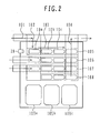
- FIG. 2 is a view showing a work area illustrating outline of sample rack carrying operations to be performed by a sample dispensing apparatus according to the embodiment of the present invention.
- the parent sample racks 10a, 10b, and 10c with the parent sample containers transferred through an external transfer line 101 mounted thereon are carried in by a carry-in mechanism 102 into the dispensing device and are transferred on a parent line 103 up to a dispensing position.
- bar code adhered to each rack is read with a bar code reader 20, and the rack is identified according to the rack ID.
- the racks with child sample containers into which the sample is dispensed are transferred to transfer lines 105, 106, 107, and 108 by a rack supply mechanism not shown, and are transferred to respective dispensing positions.
- the dispensing head 1 receives the nozzle chip 2 from chip racks 109a, 109b, and 109c each the nozzle chip 2 mounted thereon to execute operations for sucking and dispensing the sample.
- a sample rack for which the dispensing operation has been completed is carried out by the carry-out mechanism 104 onto the external transfer line 101 and is transferred for subsequent treatment.
- FIG. 3 is a view illustrating outline of an example of a flow of processing to be controlled by the dispensing control CPU 340.
- the dispensing control CPU 340 communicates with the transfer path control CPU 330 to acquire instructive information for dispensing and carries the parent sample racks 10a, 10b, 10c into the dispensing device.
- the dispensing control CPU 340 reads IDs of the parent sample racks 10a, 10b, 10c from the bar code or the like, and transmits the information to the host CPU, and receives instructive information for dispensing the sample.
- the nozzle chip 2 When the nozzle chip 2 is not set on the dispensing head 1, an operation for setting the nozzle chip 2 on the dispensing head 1 is performed.
- the sample is sucked from the parent sample container 3 according to the instructive information for dispensing.
- the sample is discharged to a child sample container for an analyzer by a content instructed by the instructive information.
- the dispensing control CPU 340 determines whether an operation of discharging the sample to all of the child sample containers has been finished, and the child sample containers are exchanged with new ones if the dispensing control CPU 340 determines that the discharging operation has been finished.
- the dispensing control CPU 340 measures the time it takes to exchange the child sample containers, and when exchange of all the child sample containers is not finished within a prespecified period of time, a nozzle chip 3 set on the dispensing head 1 is discarded.
- a counter for time measurement may be reset at a time point of start of each dispensing operation or before measurement of time is started.
- the dispensing control CPU 340 transmits information concerning a result of dispensing to the host CPU 320. Then the dispensing control CPU 340 communicates with the transfer path control CPU 330 to transfer the parent sample racks 10a, 10b, 10c with the parent sample containers 3 set thereon respectively and the child sample racks with the child sample containers mounted thereon respectively onto transfer lines 105, 106, 107, and 108 outside the dispensing device.
- the time it takes for dispensing it is required to measure any of the time it takes to exchange the child sample containers, the time when the nozzle chip is set on the dispensing head, a period of elapsed time after the end of last operation of sucking or discharging a sample, or the like. During the elapsed time, an operation of dispensing the sample cannot be performed. When the elapsed time is over a prespecified period of time, the nozzle chip is released from the dispensing head.
- a configuration is preferable in which the time previously specified can be set from the host CPU or the dispensing control CPU.
- an operation may be carried out to discharge back the sample remaining in the nozzle chip to the original parent sample container before discard of the nozzle chip.
- the discharge back should be started not from a tip position of the nozzle chip at the time point when the sucking operation is terminated, but from a portion above a level of a sample liquid in the parent sample container.
Landscapes
- General Health & Medical Sciences (AREA)
- Health & Medical Sciences (AREA)
- Life Sciences & Earth Sciences (AREA)
- Chemical & Material Sciences (AREA)
- Analytical Chemistry (AREA)
- Biochemistry (AREA)
- Physics & Mathematics (AREA)
- General Physics & Mathematics (AREA)
- Immunology (AREA)
- Pathology (AREA)
- Automatic Analysis And Handling Materials Therefor (AREA)
- Sampling And Sample Adjustment (AREA)
- Mechanical Treatment Of Semiconductor (AREA)
Applications Claiming Priority (1)
| Application Number | Priority Date | Filing Date | Title |
|---|---|---|---|
| JP2006354675A JP4891059B2 (ja) | 2006-12-28 | 2006-12-28 | 検体分注処理装置 |
Publications (3)
| Publication Number | Publication Date |
|---|---|
| EP1939631A2 true EP1939631A2 (de) | 2008-07-02 |
| EP1939631A3 EP1939631A3 (de) | 2009-06-24 |
| EP1939631B1 EP1939631B1 (de) | 2011-04-06 |
Family
ID=39232934
Family Applications (1)
| Application Number | Title | Priority Date | Filing Date |
|---|---|---|---|
| EP07025140A Active EP1939631B1 (de) | 2006-12-28 | 2007-12-27 | Probenabgabevorrichtung |
Country Status (6)
| Country | Link |
|---|---|
| US (1) | US7823469B2 (de) |
| EP (1) | EP1939631B1 (de) |
| JP (1) | JP4891059B2 (de) |
| CN (1) | CN101210933A (de) |
| AT (1) | ATE504839T1 (de) |
| DE (1) | DE602007013680D1 (de) |
Cited By (2)
| Publication number | Priority date | Publication date | Assignee | Title |
|---|---|---|---|---|
| US11460383B2 (en) | 2016-06-16 | 2022-10-04 | Nanocytomics, LLC | Automated staining system |
| US11573242B2 (en) | 2015-04-06 | 2023-02-07 | Nanocytomics, LLC | Automated specimen deposition systems and associated methods |
Families Citing this family (5)
| Publication number | Priority date | Publication date | Assignee | Title |
|---|---|---|---|---|
| JP5506189B2 (ja) * | 2008-12-26 | 2014-05-28 | 株式会社日立ハイテクノロジーズ | 自動分析装置 |
| IT1393352B1 (it) * | 2009-03-16 | 2012-04-20 | Inpeco Ip Ltd Ora Inpeco Holding Ltd | Apparato di aliquotazione di contenitori di materiale biologico. |
| CN107076770B (zh) * | 2014-07-28 | 2019-07-12 | 道格拉斯科学有限责任公司 | 用于分析生物样本和试剂的仪器 |
| US9586399B2 (en) * | 2015-03-30 | 2017-03-07 | Funai Electric Co., Ltd. | Fluid ejection device for depositing a discrete quantity of fluid onto a surface |
| JP7223577B2 (ja) * | 2016-06-17 | 2023-02-16 | シーメンス・ヘルスケア・ダイアグノスティックス・インコーポレイテッド | 流体試料の再使用により流体試料を多重化するための装置、方法およびキット |
Citations (4)
| Publication number | Priority date | Publication date | Assignee | Title |
|---|---|---|---|---|
| US5178834A (en) | 1989-07-19 | 1993-01-12 | Tosoh Corporation | Automatic immunoassay analyzer |
| EP0733905A2 (de) | 1995-03-24 | 1996-09-25 | Becton, Dickinson and Company | System für diagnostischen Nukleinsäuretest |
| US5627522A (en) | 1992-03-27 | 1997-05-06 | Abbott Laboratories | Automated liquid level sensing system |
| AU2004200814A1 (en) | 1997-11-27 | 2004-03-25 | Aim Lab Automation Technologies Pty Ltd | A sample distribution apparatus/system |
Family Cites Families (4)
| Publication number | Priority date | Publication date | Assignee | Title |
|---|---|---|---|---|
| JPH0894638A (ja) * | 1994-09-21 | 1996-04-12 | Fuji Photo Film Co Ltd | 生化学分析装置 |
| JP3029387B2 (ja) * | 1995-06-07 | 2000-04-04 | アロカ株式会社 | 漏れ検出機能を備えた自動分注装置及び該装置における漏れ検出方法 |
| JP3410018B2 (ja) * | 1998-04-20 | 2003-05-26 | 株式会社日立製作所 | 検体分注装置及び検体処理システム |
| US6370942B1 (en) | 2000-05-15 | 2002-04-16 | Dade Behring Inc. | Method for verifying the integrity of a fluid transfer |
-
2006
- 2006-12-28 JP JP2006354675A patent/JP4891059B2/ja active Active
-
2007
- 2007-12-27 EP EP07025140A patent/EP1939631B1/de active Active
- 2007-12-27 AT AT07025140T patent/ATE504839T1/de not_active IP Right Cessation
- 2007-12-27 CN CN200710300434.3A patent/CN101210933A/zh active Pending
- 2007-12-27 US US11/964,951 patent/US7823469B2/en active Active
- 2007-12-27 DE DE602007013680T patent/DE602007013680D1/de active Active
Patent Citations (4)
| Publication number | Priority date | Publication date | Assignee | Title |
|---|---|---|---|---|
| US5178834A (en) | 1989-07-19 | 1993-01-12 | Tosoh Corporation | Automatic immunoassay analyzer |
| US5627522A (en) | 1992-03-27 | 1997-05-06 | Abbott Laboratories | Automated liquid level sensing system |
| EP0733905A2 (de) | 1995-03-24 | 1996-09-25 | Becton, Dickinson and Company | System für diagnostischen Nukleinsäuretest |
| AU2004200814A1 (en) | 1997-11-27 | 2004-03-25 | Aim Lab Automation Technologies Pty Ltd | A sample distribution apparatus/system |
Cited By (4)
| Publication number | Priority date | Publication date | Assignee | Title |
|---|---|---|---|---|
| US11573242B2 (en) | 2015-04-06 | 2023-02-07 | Nanocytomics, LLC | Automated specimen deposition systems and associated methods |
| US12158475B2 (en) | 2015-04-06 | 2024-12-03 | Nanocytomics, LLC | Automated specimen deposition systems and associated methods |
| US11460383B2 (en) | 2016-06-16 | 2022-10-04 | Nanocytomics, LLC | Automated staining system |
| US12066364B2 (en) | 2016-06-16 | 2024-08-20 | Nanocytomics, LLC | Automated staining system |
Also Published As
| Publication number | Publication date |
|---|---|
| EP1939631B1 (de) | 2011-04-06 |
| ATE504839T1 (de) | 2011-04-15 |
| US20080156118A1 (en) | 2008-07-03 |
| EP1939631A3 (de) | 2009-06-24 |
| CN101210933A (zh) | 2008-07-02 |
| DE602007013680D1 (de) | 2011-05-19 |
| JP4891059B2 (ja) | 2012-03-07 |
| US7823469B2 (en) | 2010-11-02 |
| JP2008164456A (ja) | 2008-07-17 |
Similar Documents
| Publication | Publication Date | Title |
|---|---|---|
| US7823469B2 (en) | Sample dispensing apparatus | |
| JP4434357B2 (ja) | 自動分析装置 | |
| US8354078B2 (en) | Liquid aspirating tube, liquid dispensing apparatus and liquid dispensing method | |
| JP5686744B2 (ja) | 自動分析装置 | |
| CN101218029B (zh) | 保证所执行的分析的追踪能力的自动吸移设备 | |
| US7556771B2 (en) | Automatic analyzing system | |
| CN110023765A (zh) | 自动分析装置 | |
| US20070166194A1 (en) | Automatic blood analyzer | |
| JP5260995B2 (ja) | 分析システムおよび分析装置 | |
| JPH0666813A (ja) | 自動分析装置 | |
| JP4949109B2 (ja) | 液体分注装置、検体測定装置および液体分注方法 | |
| JP3905480B2 (ja) | 液状試料自動分析装置 | |
| JP2000206123A (ja) | 分注装置 | |
| JP7229335B2 (ja) | 自動分析装置および自動分析方法 | |
| WO2021066165A1 (ja) | 分析装置、分析方法および分析プログラム | |
| JP4681919B2 (ja) | 自動分注機構を備えた定性分析装置 | |
| JP5258090B2 (ja) | 自動分析装置 | |
| JP2008249659A (ja) | 液体吸引管、液体分注装置および検体測定装置 | |
| JP4486006B2 (ja) | 検体分注処理装置 | |
| JP2003315351A (ja) | 極微量血液自動分析装置 | |
| JPH11118809A (ja) | 分注装置 | |
| JPH0726766U (ja) | 血液凝固分析装置 | |
| JP2007322394A (ja) | 分注装置および自動分析装置 | |
| WO2006041136A1 (ja) | 試料容器およびその試料容器が適用される分注・廃液装置 | |
| EP1293782B1 (de) | Automatische Analysevorrichtung |
Legal Events
| Date | Code | Title | Description |
|---|---|---|---|
| PUAI | Public reference made under article 153(3) epc to a published international application that has entered the european phase |
Free format text: ORIGINAL CODE: 0009012 |
|
| 17P | Request for examination filed |
Effective date: 20080331 |
|
| AK | Designated contracting states |
Kind code of ref document: A2 Designated state(s): AT BE BG CH CY CZ DE DK EE ES FI FR GB GR HU IE IS IT LI LT LU LV MC MT NL PL PT RO SE SI SK TR |
|
| AX | Request for extension of the european patent |
Extension state: AL BA HR MK RS |
|
| PUAL | Search report despatched |
Free format text: ORIGINAL CODE: 0009013 |
|
| AK | Designated contracting states |
Kind code of ref document: A3 Designated state(s): AT BE BG CH CY CZ DE DK EE ES FI FR GB GR HU IE IS IT LI LT LU LV MC MT NL PL PT RO SE SI SK TR |
|
| AX | Request for extension of the european patent |
Extension state: AL BA HR MK RS |
|
| 17Q | First examination report despatched |
Effective date: 20090828 |
|
| AKX | Designation fees paid |
Designated state(s): AT BE BG CH CY CZ DE DK EE ES FI FR GB GR HU IE IS IT LI LT LU LV MC MT NL PL PT RO SE SI SK TR |
|
| GRAP | Despatch of communication of intention to grant a patent |
Free format text: ORIGINAL CODE: EPIDOSNIGR1 |
|
| GRAS | Grant fee paid |
Free format text: ORIGINAL CODE: EPIDOSNIGR3 |
|
| GRAA | (expected) grant |
Free format text: ORIGINAL CODE: 0009210 |
|
| RIN1 | Information on inventor provided before grant (corrected) |
Inventor name: HAGIYA, SATOSHI Inventor name: TAKAYA, EIJI Inventor name: OIZUMI, JUNICHI Inventor name: KAKUNO, MASAHITO Inventor name: SUZUKI, NOBUO |
|
| AK | Designated contracting states |
Kind code of ref document: B1 Designated state(s): AT BE BG CH CY CZ DE DK EE ES FI FR GB GR HU IE IS IT LI LT LU LV MC MT NL PL PT RO SE SI SK TR |
|
| REG | Reference to a national code |
Ref country code: GB Ref legal event code: FG4D |
|
| REG | Reference to a national code |
Ref country code: CH Ref legal event code: EP |
|
| REG | Reference to a national code |
Ref country code: IE Ref legal event code: FG4D |
|
| REF | Corresponds to: |
Ref document number: 602007013680 Country of ref document: DE Date of ref document: 20110519 Kind code of ref document: P |
|
| REG | Reference to a national code |
Ref country code: DE Ref legal event code: R096 Ref document number: 602007013680 Country of ref document: DE Effective date: 20110519 |
|
| REG | Reference to a national code |
Ref country code: NL Ref legal event code: VDEP Effective date: 20110406 |
|
| PG25 | Lapsed in a contracting state [announced via postgrant information from national office to epo] |
Ref country code: SI Free format text: LAPSE BECAUSE OF FAILURE TO SUBMIT A TRANSLATION OF THE DESCRIPTION OR TO PAY THE FEE WITHIN THE PRESCRIBED TIME-LIMIT Effective date: 20110406 |
|
| LTIE | Lt: invalidation of european patent or patent extension |
Effective date: 20110406 |
|
| PG25 | Lapsed in a contracting state [announced via postgrant information from national office to epo] |
Ref country code: LT Free format text: LAPSE BECAUSE OF FAILURE TO SUBMIT A TRANSLATION OF THE DESCRIPTION OR TO PAY THE FEE WITHIN THE PRESCRIBED TIME-LIMIT Effective date: 20110406 Ref country code: SE Free format text: LAPSE BECAUSE OF FAILURE TO SUBMIT A TRANSLATION OF THE DESCRIPTION OR TO PAY THE FEE WITHIN THE PRESCRIBED TIME-LIMIT Effective date: 20110406 Ref country code: PT Free format text: LAPSE BECAUSE OF FAILURE TO SUBMIT A TRANSLATION OF THE DESCRIPTION OR TO PAY THE FEE WITHIN THE PRESCRIBED TIME-LIMIT Effective date: 20110808 |
|
| PG25 | Lapsed in a contracting state [announced via postgrant information from national office to epo] |
Ref country code: AT Free format text: LAPSE BECAUSE OF FAILURE TO SUBMIT A TRANSLATION OF THE DESCRIPTION OR TO PAY THE FEE WITHIN THE PRESCRIBED TIME-LIMIT Effective date: 20110406 Ref country code: IS Free format text: LAPSE BECAUSE OF FAILURE TO SUBMIT A TRANSLATION OF THE DESCRIPTION OR TO PAY THE FEE WITHIN THE PRESCRIBED TIME-LIMIT Effective date: 20110806 Ref country code: FI Free format text: LAPSE BECAUSE OF FAILURE TO SUBMIT A TRANSLATION OF THE DESCRIPTION OR TO PAY THE FEE WITHIN THE PRESCRIBED TIME-LIMIT Effective date: 20110406 Ref country code: GR Free format text: LAPSE BECAUSE OF FAILURE TO SUBMIT A TRANSLATION OF THE DESCRIPTION OR TO PAY THE FEE WITHIN THE PRESCRIBED TIME-LIMIT Effective date: 20110707 Ref country code: CY Free format text: LAPSE BECAUSE OF FAILURE TO SUBMIT A TRANSLATION OF THE DESCRIPTION OR TO PAY THE FEE WITHIN THE PRESCRIBED TIME-LIMIT Effective date: 20110406 Ref country code: LV Free format text: LAPSE BECAUSE OF FAILURE TO SUBMIT A TRANSLATION OF THE DESCRIPTION OR TO PAY THE FEE WITHIN THE PRESCRIBED TIME-LIMIT Effective date: 20110406 Ref country code: ES Free format text: LAPSE BECAUSE OF FAILURE TO SUBMIT A TRANSLATION OF THE DESCRIPTION OR TO PAY THE FEE WITHIN THE PRESCRIBED TIME-LIMIT Effective date: 20110717 Ref country code: BE Free format text: LAPSE BECAUSE OF FAILURE TO SUBMIT A TRANSLATION OF THE DESCRIPTION OR TO PAY THE FEE WITHIN THE PRESCRIBED TIME-LIMIT Effective date: 20110406 |
|
| PG25 | Lapsed in a contracting state [announced via postgrant information from national office to epo] |
Ref country code: NL Free format text: LAPSE BECAUSE OF FAILURE TO SUBMIT A TRANSLATION OF THE DESCRIPTION OR TO PAY THE FEE WITHIN THE PRESCRIBED TIME-LIMIT Effective date: 20110406 |
|
| PG25 | Lapsed in a contracting state [announced via postgrant information from national office to epo] |
Ref country code: EE Free format text: LAPSE BECAUSE OF FAILURE TO SUBMIT A TRANSLATION OF THE DESCRIPTION OR TO PAY THE FEE WITHIN THE PRESCRIBED TIME-LIMIT Effective date: 20110406 Ref country code: CZ Free format text: LAPSE BECAUSE OF FAILURE TO SUBMIT A TRANSLATION OF THE DESCRIPTION OR TO PAY THE FEE WITHIN THE PRESCRIBED TIME-LIMIT Effective date: 20110406 |
|
| PLBE | No opposition filed within time limit |
Free format text: ORIGINAL CODE: 0009261 |
|
| STAA | Information on the status of an ep patent application or granted ep patent |
Free format text: STATUS: NO OPPOSITION FILED WITHIN TIME LIMIT |
|
| PG25 | Lapsed in a contracting state [announced via postgrant information from national office to epo] |
Ref country code: SK Free format text: LAPSE BECAUSE OF FAILURE TO SUBMIT A TRANSLATION OF THE DESCRIPTION OR TO PAY THE FEE WITHIN THE PRESCRIBED TIME-LIMIT Effective date: 20110406 Ref country code: PL Free format text: LAPSE BECAUSE OF FAILURE TO SUBMIT A TRANSLATION OF THE DESCRIPTION OR TO PAY THE FEE WITHIN THE PRESCRIBED TIME-LIMIT Effective date: 20110406 Ref country code: DK Free format text: LAPSE BECAUSE OF FAILURE TO SUBMIT A TRANSLATION OF THE DESCRIPTION OR TO PAY THE FEE WITHIN THE PRESCRIBED TIME-LIMIT Effective date: 20110406 Ref country code: RO Free format text: LAPSE BECAUSE OF FAILURE TO SUBMIT A TRANSLATION OF THE DESCRIPTION OR TO PAY THE FEE WITHIN THE PRESCRIBED TIME-LIMIT Effective date: 20110406 |
|
| 26N | No opposition filed |
Effective date: 20120110 |
|
| REG | Reference to a national code |
Ref country code: DE Ref legal event code: R097 Ref document number: 602007013680 Country of ref document: DE Effective date: 20120110 |
|
| PG25 | Lapsed in a contracting state [announced via postgrant information from national office to epo] |
Ref country code: MC Free format text: LAPSE BECAUSE OF NON-PAYMENT OF DUE FEES Effective date: 20111231 |
|
| REG | Reference to a national code |
Ref country code: CH Ref legal event code: PL |
|
| GBPC | Gb: european patent ceased through non-payment of renewal fee |
Effective date: 20111227 |
|
| REG | Reference to a national code |
Ref country code: IE Ref legal event code: MM4A |
|
| PG25 | Lapsed in a contracting state [announced via postgrant information from national office to epo] |
Ref country code: IE Free format text: LAPSE BECAUSE OF NON-PAYMENT OF DUE FEES Effective date: 20111227 Ref country code: LI Free format text: LAPSE BECAUSE OF NON-PAYMENT OF DUE FEES Effective date: 20111231 Ref country code: GB Free format text: LAPSE BECAUSE OF NON-PAYMENT OF DUE FEES Effective date: 20111227 Ref country code: CH Free format text: LAPSE BECAUSE OF NON-PAYMENT OF DUE FEES Effective date: 20111231 |
|
| PG25 | Lapsed in a contracting state [announced via postgrant information from national office to epo] |
Ref country code: MT Free format text: LAPSE BECAUSE OF FAILURE TO SUBMIT A TRANSLATION OF THE DESCRIPTION OR TO PAY THE FEE WITHIN THE PRESCRIBED TIME-LIMIT Effective date: 20110406 |
|
| PG25 | Lapsed in a contracting state [announced via postgrant information from national office to epo] |
Ref country code: LU Free format text: LAPSE BECAUSE OF NON-PAYMENT OF DUE FEES Effective date: 20111227 |
|
| PG25 | Lapsed in a contracting state [announced via postgrant information from national office to epo] |
Ref country code: BG Free format text: LAPSE BECAUSE OF FAILURE TO SUBMIT A TRANSLATION OF THE DESCRIPTION OR TO PAY THE FEE WITHIN THE PRESCRIBED TIME-LIMIT Effective date: 20110706 |
|
| PG25 | Lapsed in a contracting state [announced via postgrant information from national office to epo] |
Ref country code: TR Free format text: LAPSE BECAUSE OF FAILURE TO SUBMIT A TRANSLATION OF THE DESCRIPTION OR TO PAY THE FEE WITHIN THE PRESCRIBED TIME-LIMIT Effective date: 20110406 |
|
| PG25 | Lapsed in a contracting state [announced via postgrant information from national office to epo] |
Ref country code: HU Free format text: LAPSE BECAUSE OF FAILURE TO SUBMIT A TRANSLATION OF THE DESCRIPTION OR TO PAY THE FEE WITHIN THE PRESCRIBED TIME-LIMIT Effective date: 20110406 |
|
| PG25 | Lapsed in a contracting state [announced via postgrant information from national office to epo] |
Ref country code: IT Free format text: LAPSE BECAUSE OF FAILURE TO SUBMIT A TRANSLATION OF THE DESCRIPTION OR TO PAY THE FEE WITHIN THE PRESCRIBED TIME-LIMIT Effective date: 20110406 |
|
| REG | Reference to a national code |
Ref country code: FR Ref legal event code: PLFP Year of fee payment: 9 |
|
| REG | Reference to a national code |
Ref country code: FR Ref legal event code: PLFP Year of fee payment: 10 |
|
| REG | Reference to a national code |
Ref country code: FR Ref legal event code: PLFP Year of fee payment: 11 |
|
| REG | Reference to a national code |
Ref country code: DE Ref legal event code: R082 Ref document number: 602007013680 Country of ref document: DE Representative=s name: STREHL SCHUEBEL-HOPF & PARTNER MBB PATENTANWAE, DE Ref country code: DE Ref legal event code: R081 Ref document number: 602007013680 Country of ref document: DE Owner name: HITACHI HIGH-TECH CORPORATION, JP Free format text: FORMER OWNER: HITACHI HIGH-TECHNOLOGIES CORPORATION, TOKYO, JP |
|
| PGFP | Annual fee paid to national office [announced via postgrant information from national office to epo] |
Ref country code: DE Payment date: 20251126 Year of fee payment: 19 |
|
| PGFP | Annual fee paid to national office [announced via postgrant information from national office to epo] |
Ref country code: FR Payment date: 20251120 Year of fee payment: 19 |