EP1939115A2 - Ladevorrichtung eines Behälters mit Festteilchen und Verfahren, bei dem diese Vorrichtung zum Einsatz kommt - Google Patents
Ladevorrichtung eines Behälters mit Festteilchen und Verfahren, bei dem diese Vorrichtung zum Einsatz kommt Download PDFInfo
- Publication number
- EP1939115A2 EP1939115A2 EP08006670A EP08006670A EP1939115A2 EP 1939115 A2 EP1939115 A2 EP 1939115A2 EP 08006670 A EP08006670 A EP 08006670A EP 08006670 A EP08006670 A EP 08006670A EP 1939115 A2 EP1939115 A2 EP 1939115A2
- Authority
- EP
- European Patent Office
- Prior art keywords
- sleeve
- flexible
- particles
- enclosure
- ramp
- Prior art date
- Legal status (The legal status is an assumption and is not a legal conclusion. Google has not performed a legal analysis and makes no representation as to the accuracy of the status listed.)
- Granted
Links
- 239000002245 particle Substances 0.000 title claims abstract description 50
- 238000011068 loading method Methods 0.000 title claims abstract description 32
- 239000007787 solid Substances 0.000 title claims abstract description 25
- 238000000034 method Methods 0.000 title claims abstract description 19
- 239000000463 material Substances 0.000 claims abstract description 10
- 239000004753 textile Substances 0.000 claims abstract description 6
- 239000004033 plastic Substances 0.000 claims abstract description 3
- 239000000725 suspension Substances 0.000 claims description 7
- 239000000126 substance Substances 0.000 claims description 6
- 239000000835 fiber Substances 0.000 claims description 3
- 239000004744 fabric Substances 0.000 abstract 1
- 238000012360 testing method Methods 0.000 description 11
- 239000011324 bead Substances 0.000 description 5
- 239000002184 metal Substances 0.000 description 5
- 238000005304 joining Methods 0.000 description 4
- 229920005989 resin Polymers 0.000 description 4
- 239000011347 resin Substances 0.000 description 4
- 239000003054 catalyst Substances 0.000 description 3
- 229920001971 elastomer Polymers 0.000 description 3
- 238000005096 rolling process Methods 0.000 description 3
- PNEYBMLMFCGWSK-UHFFFAOYSA-N aluminium oxide Inorganic materials [O-2].[O-2].[O-2].[Al+3].[Al+3] PNEYBMLMFCGWSK-UHFFFAOYSA-N 0.000 description 2
- 230000003197 catalytic effect Effects 0.000 description 2
- 238000002788 crimping Methods 0.000 description 2
- 239000005060 rubber Substances 0.000 description 2
- 240000000966 Allium tricoccum Species 0.000 description 1
- 229920000742 Cotton Polymers 0.000 description 1
- 229910000831 Steel Inorganic materials 0.000 description 1
- WYTGDNHDOZPMIW-RCBQFDQVSA-N alstonine Natural products C1=CC2=C3C=CC=CC3=NC2=C2N1C[C@H]1[C@H](C)OC=C(C(=O)OC)[C@H]1C2 WYTGDNHDOZPMIW-RCBQFDQVSA-N 0.000 description 1
- MTAZNLWOLGHBHU-UHFFFAOYSA-N butadiene-styrene rubber Chemical compound C=CC=C.C=CC1=CC=CC=C1 MTAZNLWOLGHBHU-UHFFFAOYSA-N 0.000 description 1
- 229910010293 ceramic material Inorganic materials 0.000 description 1
- 239000002131 composite material Substances 0.000 description 1
- 230000001627 detrimental effect Effects 0.000 description 1
- 230000000694 effects Effects 0.000 description 1
- 239000000806 elastomer Substances 0.000 description 1
- 239000012634 fragment Substances 0.000 description 1
- 230000005484 gravity Effects 0.000 description 1
- 238000009863 impact test Methods 0.000 description 1
- 238000003780 insertion Methods 0.000 description 1
- 230000037431 insertion Effects 0.000 description 1
- 239000007769 metal material Substances 0.000 description 1
- 239000011236 particulate material Substances 0.000 description 1
- 239000008188 pellet Substances 0.000 description 1
- 239000003208 petroleum Substances 0.000 description 1
- 239000002985 plastic film Substances 0.000 description 1
- 230000003014 reinforcing effect Effects 0.000 description 1
- 238000012163 sequencing technique Methods 0.000 description 1
- 238000004904 shortening Methods 0.000 description 1
- 239000010959 steel Substances 0.000 description 1
- 229920001169 thermoplastic Polymers 0.000 description 1
- 239000004634 thermosetting polymer Substances 0.000 description 1
- 239000004416 thermosoftening plastic Substances 0.000 description 1
Images


Classifications
-
- B—PERFORMING OPERATIONS; TRANSPORTING
- B65—CONVEYING; PACKING; STORING; HANDLING THIN OR FILAMENTARY MATERIAL
- B65G—TRANSPORT OR STORAGE DEVICES, e.g. CONVEYORS FOR LOADING OR TIPPING, SHOP CONVEYOR SYSTEMS OR PNEUMATIC TUBE CONVEYORS
- B65G11/00—Chutes
- B65G11/20—Auxiliary devices, e.g. for deflecting, controlling speed of, or agitating articles or solids
- B65G11/203—Auxiliary devices, e.g. for deflecting, controlling speed of, or agitating articles or solids for articles
-
- B—PERFORMING OPERATIONS; TRANSPORTING
- B01—PHYSICAL OR CHEMICAL PROCESSES OR APPARATUS IN GENERAL
- B01J—CHEMICAL OR PHYSICAL PROCESSES, e.g. CATALYSIS OR COLLOID CHEMISTRY; THEIR RELEVANT APPARATUS
- B01J8/00—Chemical or physical processes in general, conducted in the presence of fluids and solid particles; Apparatus for such processes
- B01J8/0015—Feeding of the particles in the reactor; Evacuation of the particles out of the reactor
- B01J8/003—Feeding of the particles in the reactor; Evacuation of the particles out of the reactor in a downward flow
-
- B—PERFORMING OPERATIONS; TRANSPORTING
- B01—PHYSICAL OR CHEMICAL PROCESSES OR APPARATUS IN GENERAL
- B01J—CHEMICAL OR PHYSICAL PROCESSES, e.g. CATALYSIS OR COLLOID CHEMISTRY; THEIR RELEVANT APPARATUS
- B01J8/00—Chemical or physical processes in general, conducted in the presence of fluids and solid particles; Apparatus for such processes
- B01J8/02—Chemical or physical processes in general, conducted in the presence of fluids and solid particles; Apparatus for such processes with stationary particles, e.g. in fixed beds
- B01J8/06—Chemical or physical processes in general, conducted in the presence of fluids and solid particles; Apparatus for such processes with stationary particles, e.g. in fixed beds in tube reactors; the solid particles being arranged in tubes
-
- B—PERFORMING OPERATIONS; TRANSPORTING
- B65—CONVEYING; PACKING; STORING; HANDLING THIN OR FILAMENTARY MATERIAL
- B65G—TRANSPORT OR STORAGE DEVICES, e.g. CONVEYORS FOR LOADING OR TIPPING, SHOP CONVEYOR SYSTEMS OR PNEUMATIC TUBE CONVEYORS
- B65G11/00—Chutes
- B65G11/06—Chutes of helical or spiral form
- B65G11/066—Chutes of helical or spiral form for bulk
-
- B—PERFORMING OPERATIONS; TRANSPORTING
- B65—CONVEYING; PACKING; STORING; HANDLING THIN OR FILAMENTARY MATERIAL
- B65G—TRANSPORT OR STORAGE DEVICES, e.g. CONVEYORS FOR LOADING OR TIPPING, SHOP CONVEYOR SYSTEMS OR PNEUMATIC TUBE CONVEYORS
- B65G11/00—Chutes
- B65G11/20—Auxiliary devices, e.g. for deflecting, controlling speed of, or agitating articles or solids
- B65G11/206—Auxiliary devices, e.g. for deflecting, controlling speed of, or agitating articles or solids for bulk
-
- B—PERFORMING OPERATIONS; TRANSPORTING
- B65—CONVEYING; PACKING; STORING; HANDLING THIN OR FILAMENTARY MATERIAL
- B65G—TRANSPORT OR STORAGE DEVICES, e.g. CONVEYORS FOR LOADING OR TIPPING, SHOP CONVEYOR SYSTEMS OR PNEUMATIC TUBE CONVEYORS
- B65G69/00—Auxiliary measures taken, or devices used, in connection with loading or unloading
- B65G69/16—Preventing pulverisation, deformation, breakage, or other mechanical damage to the goods or materials
-
- B—PERFORMING OPERATIONS; TRANSPORTING
- B01—PHYSICAL OR CHEMICAL PROCESSES OR APPARATUS IN GENERAL
- B01J—CHEMICAL OR PHYSICAL PROCESSES, e.g. CATALYSIS OR COLLOID CHEMISTRY; THEIR RELEVANT APPARATUS
- B01J2208/00—Processes carried out in the presence of solid particles; Reactors therefor
- B01J2208/00743—Feeding or discharging of solids
- B01J2208/00752—Feeding
-
- B—PERFORMING OPERATIONS; TRANSPORTING
- B01—PHYSICAL OR CHEMICAL PROCESSES OR APPARATUS IN GENERAL
- B01J—CHEMICAL OR PHYSICAL PROCESSES, e.g. CATALYSIS OR COLLOID CHEMISTRY; THEIR RELEVANT APPARATUS
- B01J2208/00—Processes carried out in the presence of solid particles; Reactors therefor
- B01J2208/00743—Feeding or discharging of solids
- B01J2208/00769—Details of feeding or discharging
- B01J2208/00778—Kinetic energy reducing devices in the flow channel
Definitions
- the present invention relates to a device and a method for charging an enclosure, in particular a large enclosure whose height can reach several tens of meters, with solid particles whose physical integrity is necessary to maintain.
- the device and the process according to the invention more particularly apply to the loading of fixed-bed reactors, of chemical or electrochemical, petroleum or petrochemical type, with solid particles which can be in the form of beads, grains or cylinders. , pellets, sticks or any other form, but which are relatively small.
- the solid particles are in particular relatively fragile solid particles that do not easily support a free fall of a height of several meters.
- These balls have a diameter generally less than 5 cm and they form at the base of the reactor - or at any other place thereof, for example on the bed support plate in the case of a double catalytic bed reactor - a bed whose thickness can reach more than two meters.
- Another technique is to load the balls using a flexible handle, with a diameter of 10 to 20 cm, operating at full load, that is to say filled with balls from one end to the other. other.
- the operator distributes the balls to the bottom of the reactor by manually adjusting the opening diameter of the lower end of the sleeve while moving it in the reactor.
- This method which does not guarantee a success rate of loading close to 100% intact logs, also presents a risk of significant accident for the operator. Indeed, in case of mishandling of the opening system or in case of tearing or stalling of the flexible sleeve which supports a large load, it can fall or empty completely and suddenly, which causes not only breakage logs but presents a considerable risk to the safety of the operator.
- the Applicant has recently proposed in its patent application FR 2 829 107 , a serpentine or helical semi-rigid sleeve in which the balls descend rolling on the inner face of the sleeve, the speed of descent and thus the kinetic energy at the end of stroke can be adjusted via the inclination of the slope.
- the device described in this application is quite satisfactory both from the point of view of the loading speed and the filling quality, but it has the disadvantage of presenting several problems of size. Indeed, the sinuous or helical shape of the device and the relative stiffness of the material of the sleeve make it difficult to transport and install and dismantle through the manhole of the reactor.
- the Applicant has set itself the objective of proposing a device for loading a reactor with solid particles which has the advantages but not the disadvantages of the device described in FR 2 829 107 in other words, a device for introducing relatively fragile particles without breaking them at the bottom of an enclosure, with a high flow rate, and having a small spatial space equivalent to that of a straight sleeve as described above. .
- the present invention therefore relates to a device for introducing solid particles into an enclosure, in particular into a chemical reactor, comprising a handle, preferably flexible and cylindrical, in which flow from above to below said particles, characterized by the fact it further comprises, inside the sleeve, at least one helical ramp fixed on and wound around a central axis, said ramp having a width such that the distance between its outer edge and the flexible sleeve is less than to the size of the solid particles to be introduced and in that the helical ramp is intended to be fixed to said enclosure by means of a suspension mechanism independent of that of the sleeve.
- the subject of the invention is also a method for charging an enclosure, in particular a large reactor, with solid particles, using such an introduction device.
- Each of the helical ramps of the device of the invention receives the solid particles introduced by the upper end of the sleeve, stopping or preventing the free fall of these in the sleeve by dragging or rolling, under the effect of the gravity, at a speed that depends essentially on the slope of said ramp.
- This device thus makes it possible to limit in a controlled manner the kinetic energy imparted to the particles during their descent into the sleeve, by modifying several of its parameters, such as the slope of the helical ramp (s) and / or the number, the length and / or the spacing of the zones of the sleeve containing such a helical ramp, or the pitch of the helical ramp (s) (s), these parameters being able to be modified individually or in combination.
- the spatial size of the device according to the invention is determined by the external dimensions of the flexible sleeve enveloping the helical ramp, and is therefore identical to that of a conventional flexible sleeve and lower than that of a sinuous or helical sleeve such as described in FR 2 829 107 .
- the operational safety of a device according to the invention is considerably increased compared to a conventional flexible sleeve because it does not generally operate at full load which considerably reduces the weight of balls or particles present in the sleeve at a given moment. .
- the weight of the balls or particles to be loaded is not, as in the case of the conventional flexible straight sleeve, supported only by the flexible sleeve, but mainly by the helical ramp which is fixed to the upper part of the reactor by a suspension mechanism independent of that of the sleeve. The risk of tearing or stalling of the flexible sleeve is thus considerably reduced.
- the central axis carrying the helical ramp may be of a rigid material, for example a metallic material or a thermoplastic or thermoset resin, or a relatively flexible material, for example a plasticized resin or an elastomer, or a composite material such as rubber or resin, reinforced with fibers or textiles.
- This central axis may have for example the shape of a tube or a solid rod.
- the ends of the central axis, or at least one axis element supporting the helical ramp, can also be mounted on pivots to allow these said axes to rotate freely under the weight of the balls being loaded, thus making it possible to accelerate said loading.
- An automation of the rotation, using a motor, for example pneumatic, can also be considered.
- the central axis is formed by a plurality of flexible or rigid axis elements, which are articulated with respect to each other.
- This articulation is particularly interesting when the central axis is a tube or a relatively rigid rod because it then advantageously increases the overall flexibility of the device and facilitates its handling.
- the design of a central axis in several elements articulated with respect to each other also allows the adjustment of the length of the device depending on the height of the reactor, or the shortening of the device as said reactor is filled. of particles.
- each of the articulated elements is preferably between 5 centimeters and 5 meters depending on the type of reactor to be charged.
- the articulation of these elements carrying the helical ramp is preferably by intermediate elements, or hinge elements.
- These intermediate elements are preferably flexible elements that do not prevent the free fall of the solid particles inside the flexible sleeve, between two helical ramps. The balls or particles to be charged thus pass successively and alternately in areas where they slide or roll on a helical ramp and in areas where they are in free fall.
- the length of the free fall zones has an influence on the filling speed. The larger the proportion and the length of free fall zones, the higher the loading speed. The length of free fall zones, however, shall not exceed an upper limit value beyond which the balls or particles may break or be damaged. This maximum length of the intermediate elements depends, of course, on the fragility of the objects to be loaded. The Applicant has found that a length of intermediate elements of between 5 centimeters and 5 meters, preferably between 0.5 and 3 meters, generally allows a fast filling with a very low breakage rate of the balls.
- the overall proportion of all the zones of free fall relative to the total length of the device according to the invention is preferably between 20% and 80%, in particular between 40 and 70%.
- intermediate elements consisting of slings, ropes, cables, chains or flexible tubes carrying at each of their ends appropriate means for attaching them to the axis elements carrying a helical ramp.
- the helical ramp may be of any material of sufficient rigidity to support the weight of the balls or particles. It can be a metal sheet, plastic or rubber, or a brush-type system.
- the helical ramp has a brush structure, the number and rigidity of the bristles forming the brush being sufficient to support the weight of the particles to be introduced when the loading rate is maximum.
- the bristles can be inserted into a suitable element that can be glued, welded or otherwise attached to the central axis.
- the helical ramp is a brush formed by crimping resin bristles in a U-shaped profile, which profile is then welded to a central metal axis, preferably a metal tube.
- the helical ramp of the device according to the present invention is preferably a single helix, but it is also possible to envisage double or multiple helices.
- the pitch, which determines the slope of the ramp and therefore the speed of rolling or sliding particles, is preferably between 5 and 100 cm, preferably between 15 and 80 cm.
- the particles In order for the boom to dampen the fall of the particles and effectively slow the descent of the particles into the sleeve, it is essential that the particles can not fall over the outer edge of the helical ramp.
- the outer edge thereof is preferably in contact with the flexible sleeve.
- the flexible sleeve may be made of any material having sufficient strength to withstand a tear during the loading process. It may be for example a textile material, preferably knitted or woven, or a plastic sheet, optionally reinforced with fibers or a textile material.
- the term "flexible" handle in the present invention not only a sleeve capable of flattening completely when empty, but also a semi-rigid sleeve, reinforced by rigid annular elements, placed at regular intervals and which allow a curvature of the sleeve but prevent the flattening thereof.
- the inside diameter of the flexible sleeve surrounding the helical ramps and the intermediate elements preferably does not exceed a few tens of centimeters, and is in particular between 50 and 400 mm, preferably between 100 and 200 mm.
- the loading device consists of a number of modules, each module comprising (i) a flexible handle segment and (ii) a segment incorporating a central axis carrying a helical ramp. and optionally (iii) an intermediate element as described above.
- the length of a flexible handle segment (i) is preferably substantially the same as the length of the segment having a central axis (ii) or the overall length of the segment having a central axis (ii) and the intermediate element (iii).
- the various modules are attached to each other both by sequencing the internal elements (central axis with helical ramp and intermediate element) and by joining the ends of the flexible handle segments. Suitable fastening and joining means are known in the art and those skilled in the art will have no difficulty in choosing the proper ones.
- the internal elements may be connected for example by appropriate fastening systems and the flexible handle segments for example by collars joining flanges provided at the ends of each of the flexible handle segments.
- the flexible sleeve (or a flexible sleeve segment) comprises, over part or all of its length, two straight folds, diametrically opposite one another , closed at their base by a seam line, each fold defining a band extending radially outwardly of the sleeve.
- the side bands thus created on each side of the sleeve facilitate gripping of the sleeve and are also used for the insertion of additional fastening means, such as eyelets.
- additional fastening means should indeed not be located in the flexible sleeve itself as this would increase the risk of tearing thereof.
- the loading device according to the present invention is used in a method of loading solid particles into large enclosures.
- the enclosure is preferably a reactor, generally a cylindrical reactor with a height of between 15 and 30 meters and a diameter of between 3 and 4 meters.
- a reactor generally a cylindrical reactor with a height of between 15 and 30 meters and a diameter of between 3 and 4 meters.
- the reactor may, however, also be a multi-tube reactor consisting of a plurality of vertical tubes each having a similar diameter.
- the filling device is used without the flexible sleeve surrounding the internal elements (central axis with helical ramp and intermediate element), that is to say the helical ramps fixed on and wound around a central axis, as well as the intermediate elements, are introduced directly into the tubes of the reactor whose walls then fulfill the function of the flexible sleeve, absent in this embodiment, consisting in preventing the balls or particles from falling by above the outer edge of the helical ramp.
- the width of the helical ramp will preferably be chosen so that the distance between the outer edge of the ramp and the reactor wall is less than the size of the solid particles to be introduced.
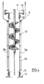
- the figure 1 shows a section of a device according to the present invention with a helical ramp (2) fixed on and wound around a central axis (3) which is here a solid rod.
- the helical ramp can be glued or welded by its base on the central rod.
- This spiral structure is wrapped by a flexible handle (1).
- This sleeve has a diameter such that the distance between the outer edge (4) of the helical ramp and the sleeve is less than the size of the particles to be loaded.
- the outer edge (4) of the ramp (2) may be in frictional contact with the inner surface of the flexible sleeve.
- the figure 2 schematically illustrates the sequence of two axis elements (6) each carrying a helical ramp (2) and separated by an intermediate element (5).
- the intermediate element (5) is connected to the axis elements (6) by a hinge means (8), for example a ring-hook system, allowing the assembly and / or disassembly easy and fast device.
- a hinge means (8) for example a ring-hook system
- the figure 3 shows a preferred embodiment of the flexible sleeve (1) used in the present invention.
- the flexible sleeve has two straight folds (7a, 7b), diametrically opposed to one another and closed at their base by a seam line (8) single or multiple.
- Each fold defines a sideband (9a, 9b) extending outwardly of the sleeve.
- One or more eyelets (10) may be provided on each sideband. These eyelets are used to hang the flexible sleeve in the part reactor (see Figure 5 ) or to secure the fixing of different modules of the device according to the invention (see Figure 4 ).
- the width of the lateral bands is not decisive but is generally between 3 and 10 cm.
- the sidebands may be doubled by a reinforcing tape (not shown), glued or secured by additional seam lines.
- the flexible sleeve is not made in one piece as on the figure 2 , but consists of several segments of flexible handle (1a) of which only one is shown here.
- This segment comprises two lateral bands (9a, 9b) formed by straight folds as explained on the figure 3 .
- a series of eyelets (10) is disposed along each sideband.
- the handle segment (la) comprises at each of its ends a flange (11) fixed to the handle segment (la) by a clamping collar (12).
- the lower flange of a first handle segment may be attached to the upper flange of the next handle segment by means of a quick fastening collar (13).
- each sideband (9a, 9b) serves to hook a safety cable (14) to prevent the lower module from stalling in case of failure of the joining system of the segments of the handle formed by the flanges (11), the clamp (12) and the quick fastening collar (13).
- figure 5 illustrates a possibility of attachment of the device of the present invention in the upper part of the reactor.
- a hopper (14) is installed in the manhole of a reactor and securely attached to the upper part thereof.
- An adapter (15) is hooked at the bottom edge of the hopper (14).
- a crossbar (16) transverse is provided in the adapter.
- the flexible sleeve (1) is secured by a clamp (17) to the adapter (15) and further hung by a suspension system (18) at the top of the reactor.
- the central axis (3) carrying the helical ramp (2) is hooked by a hook (19) to the crossbar (16) of the adapter (15).
- Two loading tests are successively carried out with two different sleeves whose heights are identical above the ground and equal to 16 meters.
- One of the handles is in accordance with the present invention and of the type described with reference to Figures 1 to 4 . It consists of a cylindrical sheath cotton woven having a thickness of 2 mm and an inner diameter of 140 mm. Said sleeve is formed of 8 modules of 2 m, each of these modules consisting of a flexible sheath and, inside the flexible sheath, two internal elements of equal length, that is to say a cable as an intermediate element and a hollow tube-shaped shaft element with a diameter of 35 mm, made of standard steel.
- the helical ramp supported by the hollow tube has a brush structure formed by crimping resin bristles in a U-shaped profile welded to the central metal axis.
- the intermediate elements and the axis elements equipped with helical ramps are connected in a conventional manner by their ends with carabiners.
- the pitch of the helix of the helical ramp is equal to 300 mm, which corresponds to a slope of 45 °, that is to say preferably between 10 ° and 80 °, and still more preferably between 20 ° and 80 °. ° and 60 °.
- the other handle is a cylindrical flexible sheath, with an internal diameter of 125 mm, suspended vertically, in which the balls fall in free fall.
- a metal plate simulating the bottom of the reactor is disposed 1 m from the lower end of each sleeve.
- Table 1 Number of broken or damaged balls with both types of loadings. testing Number of broken or damaged marbles % broken or damaged balls AT 0/66000 0.00 B 0/8000 0.00 VS 5/2000 0.25
- Table 2 Comparison of the results obtained with the sleeve according to the invention and the flexible sleeve known in the art testing % broken or damaged balls Handle according to the invention Flexible handle according to the state of the art AT 0.00 10.00 B 0.00 35,00 VS 0.25 22,00
- this device and method are not limited to this application, but can also be used for loading or unloading an enclosure with solid particles, such as catalyst particles, the integrity and physical qualities of which must be preserved.
Landscapes
- Chemical & Material Sciences (AREA)
- Organic Chemistry (AREA)
- Chemical Kinetics & Catalysis (AREA)
- Engineering & Computer Science (AREA)
- Mechanical Engineering (AREA)
- Devices And Processes Conducted In The Presence Of Fluids And Solid Particles (AREA)
- Chutes (AREA)
- Control And Other Processes For Unpacking Of Materials (AREA)
- Basic Packing Technique (AREA)
- Supplying Of Containers To The Packaging Station (AREA)
- Filling Or Emptying Of Bunkers, Hoppers, And Tanks (AREA)
- Physical Or Chemical Processes And Apparatus (AREA)
Priority Applications (1)
| Application Number | Priority Date | Filing Date | Title |
|---|---|---|---|
| PL08006670T PL1939115T3 (pl) | 2004-08-13 | 2005-08-05 | Urządzenie do załadowywania obudowy cząstkami stałymi i sposób z zastosowaniem tego urządzenia |
Applications Claiming Priority (2)
| Application Number | Priority Date | Filing Date | Title |
|---|---|---|---|
| FR0408875A FR2874212B1 (fr) | 2004-08-13 | 2004-08-13 | Dispositif de chargement d'une enceinte avec des particules solides et procede utilisant ce dispositif |
| EP05796259A EP1781557A1 (de) | 2004-08-13 | 2005-08-05 | Vorrichtung zum beladen eines behälters mit feststoffen und verfahren zur verwendung besagter vorrichtung |
Related Parent Applications (2)
| Application Number | Title | Priority Date | Filing Date |
|---|---|---|---|
| EP05796259.9 Division | 2005-08-05 | ||
| EP05796259A Division EP1781557A1 (de) | 2004-08-13 | 2005-08-05 | Vorrichtung zum beladen eines behälters mit feststoffen und verfahren zur verwendung besagter vorrichtung |
Publications (3)
| Publication Number | Publication Date |
|---|---|
| EP1939115A2 true EP1939115A2 (de) | 2008-07-02 |
| EP1939115A3 EP1939115A3 (de) | 2008-08-13 |
| EP1939115B1 EP1939115B1 (de) | 2010-05-26 |
Family
ID=34950321
Family Applications (2)
| Application Number | Title | Priority Date | Filing Date |
|---|---|---|---|
| EP05796259A Withdrawn EP1781557A1 (de) | 2004-08-13 | 2005-08-05 | Vorrichtung zum beladen eines behälters mit feststoffen und verfahren zur verwendung besagter vorrichtung |
| EP08006670A Expired - Lifetime EP1939115B1 (de) | 2004-08-13 | 2005-08-05 | Ladevorrichtung eines Behälters mit Festteilchen und Verfahren, bei dem diese Vorrichtung zum Einsatz kommt |
Family Applications Before (1)
| Application Number | Title | Priority Date | Filing Date |
|---|---|---|---|
| EP05796259A Withdrawn EP1781557A1 (de) | 2004-08-13 | 2005-08-05 | Vorrichtung zum beladen eines behälters mit feststoffen und verfahren zur verwendung besagter vorrichtung |
Country Status (16)
| Country | Link |
|---|---|
| US (1) | US7828023B2 (de) |
| EP (2) | EP1781557A1 (de) |
| JP (1) | JP5345315B2 (de) |
| CN (1) | CN101006000B (de) |
| AT (1) | ATE469064T1 (de) |
| AU (1) | AU2005276360B2 (de) |
| BR (1) | BRPI0514344A (de) |
| CA (1) | CA2575950C (de) |
| DE (1) | DE602005021556D1 (de) |
| DK (1) | DK1939115T3 (de) |
| ES (1) | ES2345172T3 (de) |
| FR (1) | FR2874212B1 (de) |
| PL (1) | PL1939115T3 (de) |
| PT (1) | PT1939115E (de) |
| WO (1) | WO2006021662A1 (de) |
| ZA (1) | ZA200701161B (de) |
Cited By (4)
| Publication number | Priority date | Publication date | Assignee | Title |
|---|---|---|---|---|
| EP3015163A1 (de) | 2014-10-31 | 2016-05-04 | Petroval | Verfahren zum Laden von Teilchenmaterial in einen vertikalen Behälter |
| CN105647455A (zh) * | 2015-12-31 | 2016-06-08 | 佛山市金银河智能装备股份有限公司 | 一种聚氨脂胶粘剂连续自动生产线和生产方法 |
| CN109516369A (zh) * | 2018-12-04 | 2019-03-26 | 内蒙古工业大学 | 一种物料下落缓冲装置 |
| CN109607034A (zh) * | 2018-12-29 | 2019-04-12 | 清华大学 | 一种球形物下落缓冲装置 |
Families Citing this family (27)
| Publication number | Priority date | Publication date | Assignee | Title |
|---|---|---|---|---|
| GB0520088D0 (en) * | 2005-10-04 | 2005-11-09 | Johnson Matthey Plc | Catalyst loading apparatus |
| EP1927395B1 (de) * | 2006-12-01 | 2009-08-12 | Haldor Topsoe A/S | Vorrichtung zur Befüllung von Rohren mit teilchenförmigem katalytischem Material und Befüllverfahren |
| MX2009014101A (es) * | 2007-07-05 | 2010-03-01 | Saudi Basic Ind Corp | Panel de reactor para procesos cataliticos. |
| US20090089184A1 (en) * | 2007-09-28 | 2009-04-02 | Embarq Holdings Company, Llc | Content portal for media distribution |
| US9156574B2 (en) * | 2007-09-28 | 2015-10-13 | Han-Tek, Inc. | Apparatus for and method of filling container with similar articles |
| NL1034894C2 (nl) * | 2008-01-08 | 2009-07-13 | Unidense Technology Gmbh | Inrichting voor het geheel of gedeeltelijk vullen van een houder. |
| US8646492B2 (en) | 2010-05-24 | 2014-02-11 | Extundo Incorporated | Device for loading catalyst into a reactor vessel |
| US9149778B2 (en) | 2010-05-24 | 2015-10-06 | Extundo Incorporated | Device and method for dispensing catalyst pellets |
| US9138709B2 (en) | 2010-05-24 | 2015-09-22 | Extundo Incorporated | Device and method for dispensing pellets |
| FR2969587B1 (fr) | 2010-12-27 | 2013-01-04 | Total Raffinage Marketing | Dispositif allege de chargement de particules solides |
| US9127425B2 (en) * | 2013-03-14 | 2015-09-08 | Meyer Products, Llc | Granular spreader assembly |
| FR2996782B1 (fr) * | 2012-10-17 | 2015-10-16 | IFP Energies Nouvelles | Systeme de chargement dense du catalyseur dans des tubes a baionnette pour reacteur echangeur de vaporeformage faisant appel a des deflecteurs amovibles |
| FR2996783B1 (fr) * | 2012-10-17 | 2014-11-21 | IFP Energies Nouvelles | Systeme de chargement dense du catalyseur dans des tubes a baionnette pour reacteur echangeur de vaporeformage faisant appel a des elements helicoidaux amovibles |
| WO2015113064A1 (en) * | 2014-01-27 | 2015-07-30 | Brush Solutions, LLC | Scrubber system |
| CN105173780A (zh) * | 2015-10-20 | 2015-12-23 | 北京首钢国际工程技术有限公司 | 一种用于料仓的旋转溜槽进料装置 |
| DK201500657A1 (en) * | 2015-10-23 | 2016-09-05 | Haldor Topsoe As | Catalyst Loading Method and Apparatus |
| HUE065680T2 (hu) * | 2016-01-28 | 2024-06-28 | T I M E Service Catalyst Handling Gmbh | Eszköz és eljárás csõ szemcsés anyaggal történõ feltöltésére |
| CN106053332B (zh) * | 2016-06-15 | 2018-12-04 | 浙江海洋大学 | 柔性纤维插入装置 |
| CN107521964A (zh) * | 2017-08-25 | 2017-12-29 | 浙江羿阳太阳能科技有限公司 | 一种硅碎片用高效收集装置 |
| CN108046396A (zh) * | 2017-12-25 | 2018-05-18 | 大连理工大学 | 一种用于吸附混凝的管道反应器 |
| WO2020203049A1 (ja) * | 2019-03-29 | 2020-10-08 | 三菱ケミカル株式会社 | 粒状物の充填方法 |
| US20200353434A1 (en) * | 2019-04-01 | 2020-11-12 | Exxonmobil Research And Engineering Company | Methods and systems for sock-loading fixed bed reactors |
| FR3109742B1 (fr) * | 2020-04-30 | 2022-05-27 | Eurecat Sa | Procédé de vidange complète d’un réacteur catalytique au moyen d’un bras articulé muni de protubérances spiralaires rotatives |
| CN111701541B (zh) * | 2020-06-19 | 2021-03-09 | 宁波巨化化工科技有限公司 | 一种气相醛加氢反应器用催化辅助装置 |
| CN115464350B (zh) * | 2021-06-01 | 2024-09-20 | 青岛航天半导体研究所有限公司 | 电气件承载盒子的螺旋传送上料工艺 |
| KR102689235B1 (ko) * | 2023-04-29 | 2024-07-26 | 이시영 | 곡물의 파손 방지장치 |
| CN117303021B (zh) * | 2023-11-01 | 2024-03-29 | 青岛汇君环境能源工程有限公司 | 一种防掉落的固体废物输送装置 |
Citations (1)
| Publication number | Priority date | Publication date | Assignee | Title |
|---|---|---|---|---|
| FR2829107A1 (fr) | 2001-08-31 | 2003-03-07 | Totalfinaelf France | Procede et dispositif pour le chargement d'une enceinte avec des particules solides |
Family Cites Families (16)
| Publication number | Priority date | Publication date | Assignee | Title |
|---|---|---|---|---|
| US96455A (en) * | 1869-11-02 | Improvement in packing-augers and spiral conveyers | ||
| GB1393179A (en) * | 1972-04-19 | 1975-05-07 | Tickhill Eng Co Ltd | Handling means for articles |
| JPS523579A (en) * | 1975-06-27 | 1977-01-12 | Sumitomo Chem Co Ltd | Method of packing |
| FR2412627A1 (fr) * | 1977-12-22 | 1979-07-20 | Rhone Poulenc Textile | Procede et dispositif pour l'obtention de fils a double constituant |
| DE4001121A1 (de) * | 1990-01-17 | 1991-07-18 | Lange Dietrich | Schneckenfoerderer |
| JPH0531351A (ja) * | 1991-07-29 | 1993-02-09 | Mitsubishi Rayon Co Ltd | 触媒の充填方法 |
| NO175579B1 (no) * | 1991-12-20 | 1994-11-03 | Unidense Technology Gmbh | Fremgangsmate og innretning for fylling av partikkelformet materiale i vertikale ror |
| FR2686964B1 (fr) * | 1992-01-30 | 1998-10-30 | Anhydride Carbonique Ind | Appareil de refroidissement cryogenique en continu de produits particulaires a caractere pateux ou solide. |
| CN1098999A (zh) * | 1993-08-18 | 1995-02-22 | 马壮 | 矿用密封式输送机 |
| CA2131262A1 (en) * | 1993-09-07 | 1995-03-08 | Shuji Morimoto | Device for transferring solid articles |
| JPH07309411A (ja) * | 1993-09-07 | 1995-11-28 | Takeda Chem Ind Ltd | 固形物搬送装置 |
| JP2000237577A (ja) * | 1998-12-25 | 2000-09-05 | Toyo Eng Corp | 触媒の充填方法および装置 |
| ES2222420T3 (es) * | 2001-08-07 | 2005-02-01 | Haldor Topsoe A/S | Procedimiento y dispositivo de carga de un catalizador. |
| NO317083B1 (no) * | 2002-09-27 | 2004-08-02 | Catalyst Services Inc | Fremgangsmate for fylling av partikulaert materiale i vertikale ror |
| JP4745223B2 (ja) * | 2003-04-24 | 2011-08-10 | クリーン ハーバーズ カタリスト テクノロジーズ, エルエルシー | 触媒を充填する方法および装置 |
| WO2006104832A2 (en) * | 2005-03-25 | 2006-10-05 | Catalyst Services, Inc. | Filling tubes with catalyst and/or other particulate |
-
2004
- 2004-08-13 FR FR0408875A patent/FR2874212B1/fr not_active Expired - Fee Related
-
2005
- 2005-08-05 EP EP05796259A patent/EP1781557A1/de not_active Withdrawn
- 2005-08-05 DE DE602005021556T patent/DE602005021556D1/de not_active Expired - Lifetime
- 2005-08-05 PL PL08006670T patent/PL1939115T3/pl unknown
- 2005-08-05 PT PT08006670T patent/PT1939115E/pt unknown
- 2005-08-05 AT AT08006670T patent/ATE469064T1/de active
- 2005-08-05 EP EP08006670A patent/EP1939115B1/de not_active Expired - Lifetime
- 2005-08-05 CA CA2575950A patent/CA2575950C/fr not_active Expired - Fee Related
- 2005-08-05 US US11/660,141 patent/US7828023B2/en not_active Expired - Fee Related
- 2005-08-05 JP JP2007525321A patent/JP5345315B2/ja not_active Expired - Fee Related
- 2005-08-05 CN CN2005800275107A patent/CN101006000B/zh not_active Expired - Fee Related
- 2005-08-05 BR BRPI0514344-6A patent/BRPI0514344A/pt not_active IP Right Cessation
- 2005-08-05 WO PCT/FR2005/002035 patent/WO2006021662A1/fr not_active Ceased
- 2005-08-05 AU AU2005276360A patent/AU2005276360B2/en not_active Ceased
- 2005-08-05 ES ES08006670T patent/ES2345172T3/es not_active Expired - Lifetime
- 2005-08-05 DK DK08006670.7T patent/DK1939115T3/da active
-
2007
- 2007-02-08 ZA ZA200701161A patent/ZA200701161B/en unknown
Patent Citations (1)
| Publication number | Priority date | Publication date | Assignee | Title |
|---|---|---|---|---|
| FR2829107A1 (fr) | 2001-08-31 | 2003-03-07 | Totalfinaelf France | Procede et dispositif pour le chargement d'une enceinte avec des particules solides |
Cited By (8)
| Publication number | Priority date | Publication date | Assignee | Title |
|---|---|---|---|---|
| EP3015163A1 (de) | 2014-10-31 | 2016-05-04 | Petroval | Verfahren zum Laden von Teilchenmaterial in einen vertikalen Behälter |
| US9669372B2 (en) | 2014-10-31 | 2017-06-06 | Petroval | Process for loading ceramic spheres into a vertical reactor |
| CN105647455A (zh) * | 2015-12-31 | 2016-06-08 | 佛山市金银河智能装备股份有限公司 | 一种聚氨脂胶粘剂连续自动生产线和生产方法 |
| CN105647455B (zh) * | 2015-12-31 | 2018-10-02 | 佛山市金银河智能装备股份有限公司 | 一种聚氨脂胶粘剂连续自动生产线和生产方法 |
| CN109516369A (zh) * | 2018-12-04 | 2019-03-26 | 内蒙古工业大学 | 一种物料下落缓冲装置 |
| CN109607034A (zh) * | 2018-12-29 | 2019-04-12 | 清华大学 | 一种球形物下落缓冲装置 |
| CN109607034B (zh) * | 2018-12-29 | 2019-11-22 | 清华大学 | 一种球形物下落缓冲装置 |
| US11661282B2 (en) | 2018-12-29 | 2023-05-30 | Tsinghua University | Spherical object falling buffer device |
Also Published As
| Publication number | Publication date |
|---|---|
| PL1939115T3 (pl) | 2010-10-29 |
| ZA200701161B (en) | 2008-07-30 |
| FR2874212B1 (fr) | 2008-02-01 |
| US20080149215A1 (en) | 2008-06-26 |
| ES2345172T3 (es) | 2010-09-16 |
| PT1939115E (pt) | 2010-07-26 |
| CN101006000B (zh) | 2013-01-30 |
| ATE469064T1 (de) | 2010-06-15 |
| JP2008509002A (ja) | 2008-03-27 |
| AU2005276360A1 (en) | 2006-03-02 |
| US7828023B2 (en) | 2010-11-09 |
| EP1781557A1 (de) | 2007-05-09 |
| CN101006000A (zh) | 2007-07-25 |
| EP1939115A3 (de) | 2008-08-13 |
| EP1939115B1 (de) | 2010-05-26 |
| AU2005276360B2 (en) | 2010-07-29 |
| BRPI0514344A (pt) | 2008-06-10 |
| FR2874212A1 (fr) | 2006-02-17 |
| CA2575950C (fr) | 2012-10-09 |
| CA2575950A1 (fr) | 2006-03-02 |
| DK1939115T3 (da) | 2010-09-13 |
| WO2006021662A1 (fr) | 2006-03-02 |
| JP5345315B2 (ja) | 2013-11-20 |
| DE602005021556D1 (de) | 2010-07-08 |
Similar Documents
| Publication | Publication Date | Title |
|---|---|---|
| EP1939115B1 (de) | Ladevorrichtung eines Behälters mit Festteilchen und Verfahren, bei dem diese Vorrichtung zum Einsatz kommt | |
| EP0803286B1 (de) | Verfahren und Vorrichtung zur homogenen Beschickung von festen Katalysatorteilchen in einen Rohrreaktor | |
| EP1776302B1 (de) | Vorrichtung und verfahren zum beladen einer kammer mit einem getrennten festkörper | |
| EP0007854A1 (de) | Verteilvorrichtung für Schüttgut in einem Raum | |
| FR2740123A1 (fr) | Procede et dispositif pour la distribution uniforme d'un solide sous forme divisee dans une enceinte | |
| EP2029463B1 (de) | Vorrichtung und verfahren zum laden von festpartikeln in eine kammer | |
| FR2927319A1 (fr) | Convoyeur a bande avec des stations de support fortement espacees les unes des autres. | |
| EP1152819B1 (de) | Verfahren und vorrichtung zum erleichtern des befüllens vertikaler rohre mit hilfe eines partikelförmigen materials | |
| EP2908931B1 (de) | Pneumatisches system für dichte katalysatorbeladung in bajonettröhren für einen dampfreformierungsreaktor-tauscher | |
| CA2884946A1 (fr) | Systeme de chargement dense du catalyseur dans des tubes a baionnette pour reacteur echangeur de vaporeformage faisant appel a des elements helicoidaux amovibles | |
| CA2816938C (fr) | Dispositif allege de chargement de particules solides | |
| FR2829107A1 (fr) | Procede et dispositif pour le chargement d'une enceinte avec des particules solides | |
| WO2009080978A2 (fr) | Dispositif pour le transport de particules, installation et procede pour le chargement d'une enceinte avec le dispositif | |
| EP0046425B1 (de) | Vorrichtung mit Förderband zum Fördern von Beton | |
| EP4433218B1 (de) | Vorrichtung zum trennen der komponenten einer mischung von fasern und granulaten mit einem gitterrost zur selektiven einschliessung dieser komponenten | |
| FR3129092A1 (fr) | Installation destinée à séparer dans un champ électrique les composants d’un mélange de fibres et de granules à l’aide d’un tribochargeur pourvu d’une grille de confinement sélectif desdits composants | |
| FR2802190A1 (fr) | Procede de positionnement de pneumatiques usages en vue de l'alimentation d'un dispositif de traitement par broyage ou par combustion | |
| BE624916A (de) | ||
| WO2014037677A1 (fr) | Dispositif de remplissage de granules, par exemple de granules de catalyseur, dans un recipient vertical allonge | |
| BE600460A (de) | ||
| FR2695920A1 (fr) | Dispositif vibrant de distribution sélective de pièces élémentaires. | |
| BE401987A (de) |
Legal Events
| Date | Code | Title | Description |
|---|---|---|---|
| PUAI | Public reference made under article 153(3) epc to a published international application that has entered the european phase |
Free format text: ORIGINAL CODE: 0009012 |
|
| AC | Divisional application: reference to earlier application |
Ref document number: 1781557 Country of ref document: EP Kind code of ref document: P |
|
| AK | Designated contracting states |
Kind code of ref document: A2 Designated state(s): AT BE BG CH CY CZ DE DK EE ES FI FR GB GR HU IE IS IT LI LT LU LV MC NL PL PT RO SE SI SK TR |
|
| AX | Request for extension of the european patent |
Extension state: AL BA HR MK RS |
|
| PUAL | Search report despatched |
Free format text: ORIGINAL CODE: 0009013 |
|
| RIC1 | Information provided on ipc code assigned before grant |
Ipc: B65G 11/06 20060101ALI20080624BHEP Ipc: B65G 69/16 20060101ALI20080624BHEP Ipc: B01J 8/06 20060101ALI20080624BHEP Ipc: B65G 11/20 20060101AFI20080529BHEP Ipc: B01J 8/00 20060101ALI20080624BHEP |
|
| AK | Designated contracting states |
Kind code of ref document: A3 Designated state(s): AT BE BG CH CY CZ DE DK EE ES FI FR GB GR HU IE IS IT LI LT LU LV MC NL PL PT RO SE SI SK TR |
|
| AX | Request for extension of the european patent |
Extension state: AL BA HR MK RS |
|
| RAP1 | Party data changed (applicant data changed or rights of an application transferred) |
Owner name: TOTAL RAFFINAGE MARKETING |
|
| 17P | Request for examination filed |
Effective date: 20090117 |
|
| AKX | Designation fees paid |
Designated state(s): AT BE BG CH CY CZ DE DK EE ES FI FR GB GR HU IE IS IT LI LT LU LV MC NL PL PT RO SE SI SK TR |
|
| GRAP | Despatch of communication of intention to grant a patent |
Free format text: ORIGINAL CODE: EPIDOSNIGR1 |
|
| GRAS | Grant fee paid |
Free format text: ORIGINAL CODE: EPIDOSNIGR3 |
|
| GRAA | (expected) grant |
Free format text: ORIGINAL CODE: 0009210 |
|
| AC | Divisional application: reference to earlier application |
Ref document number: 1781557 Country of ref document: EP Kind code of ref document: P |
|
| AK | Designated contracting states |
Kind code of ref document: B1 Designated state(s): AT BE BG CH CY CZ DE DK EE ES FI FR GB GR HU IE IS IT LI LT LU LV MC NL PL PT RO SE SI SK TR |
|
| REG | Reference to a national code |
Ref country code: GB Ref legal event code: FG4D Free format text: NOT ENGLISH |
|
| REG | Reference to a national code |
Ref country code: CH Ref legal event code: EP |
|
| REG | Reference to a national code |
Ref country code: IE Ref legal event code: FG4D Free format text: LANGUAGE OF EP DOCUMENT: FRENCH |
|
| REF | Corresponds to: |
Ref document number: 602005021556 Country of ref document: DE Date of ref document: 20100708 Kind code of ref document: P |
|
| REG | Reference to a national code |
Ref country code: CH Ref legal event code: NV Representative=s name: ARNOLD & SIEDSMA AG |
|
| REG | Reference to a national code |
Ref country code: PT Ref legal event code: SC4A Free format text: AVAILABILITY OF NATIONAL TRANSLATION Effective date: 20100719 |
|
| REG | Reference to a national code |
Ref country code: RO Ref legal event code: EPE |
|
| REG | Reference to a national code |
Ref country code: NL Ref legal event code: T3 |
|
| REG | Reference to a national code |
Ref country code: GR Ref legal event code: EP Ref document number: 20100401815 Country of ref document: GR |
|
| REG | Reference to a national code |
Ref country code: DK Ref legal event code: T3 |
|
| REG | Reference to a national code |
Ref country code: SE Ref legal event code: TRGR |
|
| REG | Reference to a national code |
Ref country code: ES Ref legal event code: FG2A Ref document number: 2345172 Country of ref document: ES Kind code of ref document: T3 |
|
| REG | Reference to a national code |
Ref country code: PL Ref legal event code: T3 |
|
| PG25 | Lapsed in a contracting state [announced via postgrant information from national office to epo] |
Ref country code: SI Free format text: LAPSE BECAUSE OF FAILURE TO SUBMIT A TRANSLATION OF THE DESCRIPTION OR TO PAY THE FEE WITHIN THE PRESCRIBED TIME-LIMIT Effective date: 20100526 Ref country code: LV Free format text: LAPSE BECAUSE OF FAILURE TO SUBMIT A TRANSLATION OF THE DESCRIPTION OR TO PAY THE FEE WITHIN THE PRESCRIBED TIME-LIMIT Effective date: 20100526 Ref country code: IS Free format text: LAPSE BECAUSE OF FAILURE TO SUBMIT A TRANSLATION OF THE DESCRIPTION OR TO PAY THE FEE WITHIN THE PRESCRIBED TIME-LIMIT Effective date: 20100926 |
|
| REG | Reference to a national code |
Ref country code: SK Ref legal event code: T3 Ref document number: E 7873 Country of ref document: SK |
|
| REG | Reference to a national code |
Ref country code: HU Ref legal event code: AG4A Ref document number: E008737 Country of ref document: HU |
|
| PG25 | Lapsed in a contracting state [announced via postgrant information from national office to epo] |
Ref country code: CY Free format text: LAPSE BECAUSE OF FAILURE TO SUBMIT A TRANSLATION OF THE DESCRIPTION OR TO PAY THE FEE WITHIN THE PRESCRIBED TIME-LIMIT Effective date: 20100526 |
|
| PG25 | Lapsed in a contracting state [announced via postgrant information from national office to epo] |
Ref country code: EE Free format text: LAPSE BECAUSE OF FAILURE TO SUBMIT A TRANSLATION OF THE DESCRIPTION OR TO PAY THE FEE WITHIN THE PRESCRIBED TIME-LIMIT Effective date: 20100526 |
|
| PG25 | Lapsed in a contracting state [announced via postgrant information from national office to epo] |
Ref country code: MC Free format text: LAPSE BECAUSE OF NON-PAYMENT OF DUE FEES Effective date: 20100831 |
|
| PLBE | No opposition filed within time limit |
Free format text: ORIGINAL CODE: 0009261 |
|
| STAA | Information on the status of an ep patent application or granted ep patent |
Free format text: STATUS: NO OPPOSITION FILED WITHIN TIME LIMIT |
|
| 26N | No opposition filed |
Effective date: 20110301 |
|
| REG | Reference to a national code |
Ref country code: DE Ref legal event code: R097 Ref document number: 602005021556 Country of ref document: DE Effective date: 20110228 |
|
| PG25 | Lapsed in a contracting state [announced via postgrant information from national office to epo] |
Ref country code: LU Free format text: LAPSE BECAUSE OF NON-PAYMENT OF DUE FEES Effective date: 20100805 |
|
| PGFP | Annual fee paid to national office [announced via postgrant information from national office to epo] |
Ref country code: CH Payment date: 20140724 Year of fee payment: 10 Ref country code: NL Payment date: 20140721 Year of fee payment: 10 Ref country code: DK Payment date: 20140722 Year of fee payment: 10 Ref country code: CZ Payment date: 20140723 Year of fee payment: 10 Ref country code: FI Payment date: 20140722 Year of fee payment: 10 Ref country code: LT Payment date: 20140723 Year of fee payment: 10 Ref country code: RO Payment date: 20140801 Year of fee payment: 10 Ref country code: DE Payment date: 20140722 Year of fee payment: 10 Ref country code: GR Payment date: 20140722 Year of fee payment: 10 Ref country code: IE Payment date: 20140723 Year of fee payment: 10 Ref country code: BG Payment date: 20140722 Year of fee payment: 10 |
|
| PGFP | Annual fee paid to national office [announced via postgrant information from national office to epo] |
Ref country code: FR Payment date: 20140822 Year of fee payment: 10 Ref country code: HU Payment date: 20140813 Year of fee payment: 10 Ref country code: TR Payment date: 20140804 Year of fee payment: 10 Ref country code: GB Payment date: 20140725 Year of fee payment: 10 Ref country code: SK Payment date: 20140724 Year of fee payment: 10 Ref country code: AT Payment date: 20140722 Year of fee payment: 10 Ref country code: ES Payment date: 20140814 Year of fee payment: 10 Ref country code: PL Payment date: 20140725 Year of fee payment: 10 Ref country code: SE Payment date: 20140724 Year of fee payment: 10 |
|
| PGFP | Annual fee paid to national office [announced via postgrant information from national office to epo] |
Ref country code: PT Payment date: 20140206 Year of fee payment: 10 Ref country code: IT Payment date: 20140728 Year of fee payment: 10 |
|
| PGFP | Annual fee paid to national office [announced via postgrant information from national office to epo] |
Ref country code: BE Payment date: 20140722 Year of fee payment: 10 |
|
| REG | Reference to a national code |
Ref country code: PT Ref legal event code: MM4A Free format text: LAPSE DUE TO NON-PAYMENT OF FEES Effective date: 20160205 |
|
| REG | Reference to a national code |
Ref country code: DE Ref legal event code: R119 Ref document number: 602005021556 Country of ref document: DE |
|
| REG | Reference to a national code |
Ref country code: LT Ref legal event code: MM4D Effective date: 20150805 |
|
| REG | Reference to a national code |
Ref country code: DK Ref legal event code: EBP Effective date: 20150831 |
|
| REG | Reference to a national code |
Ref country code: SE Ref legal event code: EUG |
|
| REG | Reference to a national code |
Ref country code: CH Ref legal event code: PL |
|
| REG | Reference to a national code |
Ref country code: AT Ref legal event code: MM01 Ref document number: 469064 Country of ref document: AT Kind code of ref document: T Effective date: 20150805 |
|
| GBPC | Gb: european patent ceased through non-payment of renewal fee |
Effective date: 20150805 |
|
| PG25 | Lapsed in a contracting state [announced via postgrant information from national office to epo] |
Ref country code: IT Free format text: LAPSE BECAUSE OF NON-PAYMENT OF DUE FEES Effective date: 20150805 Ref country code: CH Free format text: LAPSE BECAUSE OF NON-PAYMENT OF DUE FEES Effective date: 20150831 Ref country code: SK Free format text: LAPSE BECAUSE OF NON-PAYMENT OF DUE FEES Effective date: 20150805 Ref country code: BG Free format text: LAPSE BECAUSE OF NON-PAYMENT OF DUE FEES Effective date: 20160331 Ref country code: CZ Free format text: LAPSE BECAUSE OF NON-PAYMENT OF DUE FEES Effective date: 20150805 Ref country code: LI Free format text: LAPSE BECAUSE OF NON-PAYMENT OF DUE FEES Effective date: 20150831 Ref country code: LT Free format text: LAPSE BECAUSE OF NON-PAYMENT OF DUE FEES Effective date: 20150805 |
|
| REG | Reference to a national code |
Ref country code: SK Ref legal event code: MM4A Ref document number: E 7873 Country of ref document: SK Effective date: 20150805 |
|
| REG | Reference to a national code |
Ref country code: NL Ref legal event code: MM Effective date: 20150901 |
|
| PG25 | Lapsed in a contracting state [announced via postgrant information from national office to epo] |
Ref country code: FI Free format text: LAPSE BECAUSE OF NON-PAYMENT OF DUE FEES Effective date: 20150805 Ref country code: HU Free format text: LAPSE BECAUSE OF NON-PAYMENT OF DUE FEES Effective date: 20150806 Ref country code: SE Free format text: LAPSE BECAUSE OF NON-PAYMENT OF DUE FEES Effective date: 20150806 Ref country code: GR Free format text: LAPSE BECAUSE OF NON-PAYMENT OF DUE FEES Effective date: 20160303 Ref country code: AT Free format text: LAPSE BECAUSE OF NON-PAYMENT OF DUE FEES Effective date: 20150805 Ref country code: RO Free format text: LAPSE BECAUSE OF NON-PAYMENT OF DUE FEES Effective date: 20150805 Ref country code: PT Free format text: LAPSE BECAUSE OF NON-PAYMENT OF DUE FEES Effective date: 20160205 |
|
| REG | Reference to a national code |
Ref country code: IE Ref legal event code: MM4A |
|
| REG | Reference to a national code |
Ref country code: FR Ref legal event code: ST Effective date: 20160429 |
|
| REG | Reference to a national code |
Ref country code: GR Ref legal event code: ML Ref document number: 20100401815 Country of ref document: GR Effective date: 20160303 |
|
| PG25 | Lapsed in a contracting state [announced via postgrant information from national office to epo] |
Ref country code: NL Free format text: LAPSE BECAUSE OF NON-PAYMENT OF DUE FEES Effective date: 20150901 |
|
| PG25 | Lapsed in a contracting state [announced via postgrant information from national office to epo] |
Ref country code: DE Free format text: LAPSE BECAUSE OF NON-PAYMENT OF DUE FEES Effective date: 20160301 Ref country code: IE Free format text: LAPSE BECAUSE OF NON-PAYMENT OF DUE FEES Effective date: 20150805 Ref country code: GB Free format text: LAPSE BECAUSE OF NON-PAYMENT OF DUE FEES Effective date: 20150805 |
|
| PG25 | Lapsed in a contracting state [announced via postgrant information from national office to epo] |
Ref country code: DK Free format text: LAPSE BECAUSE OF NON-PAYMENT OF DUE FEES Effective date: 20150831 Ref country code: FR Free format text: LAPSE BECAUSE OF NON-PAYMENT OF DUE FEES Effective date: 20150831 |
|
| REG | Reference to a national code |
Ref country code: ES Ref legal event code: FD2A Effective date: 20160927 |
|
| PG25 | Lapsed in a contracting state [announced via postgrant information from national office to epo] |
Ref country code: PL Free format text: LAPSE BECAUSE OF NON-PAYMENT OF DUE FEES Effective date: 20150805 |
|
| PG25 | Lapsed in a contracting state [announced via postgrant information from national office to epo] |
Ref country code: ES Free format text: LAPSE BECAUSE OF NON-PAYMENT OF DUE FEES Effective date: 20150806 |
|
| PG25 | Lapsed in a contracting state [announced via postgrant information from national office to epo] |
Ref country code: BE Free format text: LAPSE BECAUSE OF NON-PAYMENT OF DUE FEES Effective date: 20150831 |
|
| PG25 | Lapsed in a contracting state [announced via postgrant information from national office to epo] |
Ref country code: TR Free format text: LAPSE BECAUSE OF NON-PAYMENT OF DUE FEES Effective date: 20150805 |