EP1939115A2 - Device for loading an enclosure with solid particles and method using this device - Google Patents
Device for loading an enclosure with solid particles and method using this device Download PDFInfo
- Publication number
- EP1939115A2 EP1939115A2 EP08006670A EP08006670A EP1939115A2 EP 1939115 A2 EP1939115 A2 EP 1939115A2 EP 08006670 A EP08006670 A EP 08006670A EP 08006670 A EP08006670 A EP 08006670A EP 1939115 A2 EP1939115 A2 EP 1939115A2
- Authority
- EP
- European Patent Office
- Prior art keywords
- sleeve
- flexible
- particles
- enclosure
- ramp
- Prior art date
- Legal status (The legal status is an assumption and is not a legal conclusion. Google has not performed a legal analysis and makes no representation as to the accuracy of the status listed.)
- Granted
Links
Images


Classifications
-
- B—PERFORMING OPERATIONS; TRANSPORTING
- B65—CONVEYING; PACKING; STORING; HANDLING THIN OR FILAMENTARY MATERIAL
- B65G—TRANSPORT OR STORAGE DEVICES, e.g. CONVEYORS FOR LOADING OR TIPPING, SHOP CONVEYOR SYSTEMS OR PNEUMATIC TUBE CONVEYORS
- B65G11/00—Chutes
- B65G11/20—Auxiliary devices, e.g. for deflecting, controlling speed of, or agitating articles or solids
- B65G11/203—Auxiliary devices, e.g. for deflecting, controlling speed of, or agitating articles or solids for articles
-
- B—PERFORMING OPERATIONS; TRANSPORTING
- B01—PHYSICAL OR CHEMICAL PROCESSES OR APPARATUS IN GENERAL
- B01J—CHEMICAL OR PHYSICAL PROCESSES, e.g. CATALYSIS OR COLLOID CHEMISTRY; THEIR RELEVANT APPARATUS
- B01J8/00—Chemical or physical processes in general, conducted in the presence of fluids and solid particles; Apparatus for such processes
- B01J8/0015—Feeding of the particles in the reactor; Evacuation of the particles out of the reactor
- B01J8/003—Feeding of the particles in the reactor; Evacuation of the particles out of the reactor in a downward flow
-
- B—PERFORMING OPERATIONS; TRANSPORTING
- B01—PHYSICAL OR CHEMICAL PROCESSES OR APPARATUS IN GENERAL
- B01J—CHEMICAL OR PHYSICAL PROCESSES, e.g. CATALYSIS OR COLLOID CHEMISTRY; THEIR RELEVANT APPARATUS
- B01J8/00—Chemical or physical processes in general, conducted in the presence of fluids and solid particles; Apparatus for such processes
- B01J8/02—Chemical or physical processes in general, conducted in the presence of fluids and solid particles; Apparatus for such processes with stationary particles, e.g. in fixed beds
- B01J8/06—Chemical or physical processes in general, conducted in the presence of fluids and solid particles; Apparatus for such processes with stationary particles, e.g. in fixed beds in tube reactors; the solid particles being arranged in tubes
-
- B—PERFORMING OPERATIONS; TRANSPORTING
- B65—CONVEYING; PACKING; STORING; HANDLING THIN OR FILAMENTARY MATERIAL
- B65G—TRANSPORT OR STORAGE DEVICES, e.g. CONVEYORS FOR LOADING OR TIPPING, SHOP CONVEYOR SYSTEMS OR PNEUMATIC TUBE CONVEYORS
- B65G11/00—Chutes
- B65G11/06—Chutes of helical or spiral form
- B65G11/066—Chutes of helical or spiral form for bulk
-
- B—PERFORMING OPERATIONS; TRANSPORTING
- B65—CONVEYING; PACKING; STORING; HANDLING THIN OR FILAMENTARY MATERIAL
- B65G—TRANSPORT OR STORAGE DEVICES, e.g. CONVEYORS FOR LOADING OR TIPPING, SHOP CONVEYOR SYSTEMS OR PNEUMATIC TUBE CONVEYORS
- B65G11/00—Chutes
- B65G11/20—Auxiliary devices, e.g. for deflecting, controlling speed of, or agitating articles or solids
- B65G11/206—Auxiliary devices, e.g. for deflecting, controlling speed of, or agitating articles or solids for bulk
-
- B—PERFORMING OPERATIONS; TRANSPORTING
- B65—CONVEYING; PACKING; STORING; HANDLING THIN OR FILAMENTARY MATERIAL
- B65G—TRANSPORT OR STORAGE DEVICES, e.g. CONVEYORS FOR LOADING OR TIPPING, SHOP CONVEYOR SYSTEMS OR PNEUMATIC TUBE CONVEYORS
- B65G69/00—Auxiliary measures taken, or devices used, in connection with loading or unloading
- B65G69/16—Preventing pulverisation, deformation, breakage, or other mechanical damage to the goods or materials
-
- B—PERFORMING OPERATIONS; TRANSPORTING
- B01—PHYSICAL OR CHEMICAL PROCESSES OR APPARATUS IN GENERAL
- B01J—CHEMICAL OR PHYSICAL PROCESSES, e.g. CATALYSIS OR COLLOID CHEMISTRY; THEIR RELEVANT APPARATUS
- B01J2208/00—Processes carried out in the presence of solid particles; Reactors therefor
- B01J2208/00743—Feeding or discharging of solids
- B01J2208/00752—Feeding
-
- B—PERFORMING OPERATIONS; TRANSPORTING
- B01—PHYSICAL OR CHEMICAL PROCESSES OR APPARATUS IN GENERAL
- B01J—CHEMICAL OR PHYSICAL PROCESSES, e.g. CATALYSIS OR COLLOID CHEMISTRY; THEIR RELEVANT APPARATUS
- B01J2208/00—Processes carried out in the presence of solid particles; Reactors therefor
- B01J2208/00743—Feeding or discharging of solids
- B01J2208/00769—Details of feeding or discharging
- B01J2208/00778—Kinetic energy reducing devices in the flow channel
Definitions
- the present invention relates to a device and a method for charging an enclosure, in particular a large enclosure whose height can reach several tens of meters, with solid particles whose physical integrity is necessary to maintain.
- the device and the process according to the invention more particularly apply to the loading of fixed-bed reactors, of chemical or electrochemical, petroleum or petrochemical type, with solid particles which can be in the form of beads, grains or cylinders. , pellets, sticks or any other form, but which are relatively small.
- the solid particles are in particular relatively fragile solid particles that do not easily support a free fall of a height of several meters.
- These balls have a diameter generally less than 5 cm and they form at the base of the reactor - or at any other place thereof, for example on the bed support plate in the case of a double catalytic bed reactor - a bed whose thickness can reach more than two meters.
- Another technique is to load the balls using a flexible handle, with a diameter of 10 to 20 cm, operating at full load, that is to say filled with balls from one end to the other. other.
- the operator distributes the balls to the bottom of the reactor by manually adjusting the opening diameter of the lower end of the sleeve while moving it in the reactor.
- This method which does not guarantee a success rate of loading close to 100% intact logs, also presents a risk of significant accident for the operator. Indeed, in case of mishandling of the opening system or in case of tearing or stalling of the flexible sleeve which supports a large load, it can fall or empty completely and suddenly, which causes not only breakage logs but presents a considerable risk to the safety of the operator.
- the Applicant has recently proposed in its patent application FR 2 829 107 , a serpentine or helical semi-rigid sleeve in which the balls descend rolling on the inner face of the sleeve, the speed of descent and thus the kinetic energy at the end of stroke can be adjusted via the inclination of the slope.
- the device described in this application is quite satisfactory both from the point of view of the loading speed and the filling quality, but it has the disadvantage of presenting several problems of size. Indeed, the sinuous or helical shape of the device and the relative stiffness of the material of the sleeve make it difficult to transport and install and dismantle through the manhole of the reactor.
- the Applicant has set itself the objective of proposing a device for loading a reactor with solid particles which has the advantages but not the disadvantages of the device described in FR 2 829 107 in other words, a device for introducing relatively fragile particles without breaking them at the bottom of an enclosure, with a high flow rate, and having a small spatial space equivalent to that of a straight sleeve as described above. .
- the present invention therefore relates to a device for introducing solid particles into an enclosure, in particular into a chemical reactor, comprising a handle, preferably flexible and cylindrical, in which flow from above to below said particles, characterized by the fact it further comprises, inside the sleeve, at least one helical ramp fixed on and wound around a central axis, said ramp having a width such that the distance between its outer edge and the flexible sleeve is less than to the size of the solid particles to be introduced and in that the helical ramp is intended to be fixed to said enclosure by means of a suspension mechanism independent of that of the sleeve.
- the subject of the invention is also a method for charging an enclosure, in particular a large reactor, with solid particles, using such an introduction device.
- Each of the helical ramps of the device of the invention receives the solid particles introduced by the upper end of the sleeve, stopping or preventing the free fall of these in the sleeve by dragging or rolling, under the effect of the gravity, at a speed that depends essentially on the slope of said ramp.
- This device thus makes it possible to limit in a controlled manner the kinetic energy imparted to the particles during their descent into the sleeve, by modifying several of its parameters, such as the slope of the helical ramp (s) and / or the number, the length and / or the spacing of the zones of the sleeve containing such a helical ramp, or the pitch of the helical ramp (s) (s), these parameters being able to be modified individually or in combination.
- the spatial size of the device according to the invention is determined by the external dimensions of the flexible sleeve enveloping the helical ramp, and is therefore identical to that of a conventional flexible sleeve and lower than that of a sinuous or helical sleeve such as described in FR 2 829 107 .
- the operational safety of a device according to the invention is considerably increased compared to a conventional flexible sleeve because it does not generally operate at full load which considerably reduces the weight of balls or particles present in the sleeve at a given moment. .
- the weight of the balls or particles to be loaded is not, as in the case of the conventional flexible straight sleeve, supported only by the flexible sleeve, but mainly by the helical ramp which is fixed to the upper part of the reactor by a suspension mechanism independent of that of the sleeve. The risk of tearing or stalling of the flexible sleeve is thus considerably reduced.
- the central axis carrying the helical ramp may be of a rigid material, for example a metallic material or a thermoplastic or thermoset resin, or a relatively flexible material, for example a plasticized resin or an elastomer, or a composite material such as rubber or resin, reinforced with fibers or textiles.
- This central axis may have for example the shape of a tube or a solid rod.
- the ends of the central axis, or at least one axis element supporting the helical ramp, can also be mounted on pivots to allow these said axes to rotate freely under the weight of the balls being loaded, thus making it possible to accelerate said loading.
- An automation of the rotation, using a motor, for example pneumatic, can also be considered.
- the central axis is formed by a plurality of flexible or rigid axis elements, which are articulated with respect to each other.
- This articulation is particularly interesting when the central axis is a tube or a relatively rigid rod because it then advantageously increases the overall flexibility of the device and facilitates its handling.
- the design of a central axis in several elements articulated with respect to each other also allows the adjustment of the length of the device depending on the height of the reactor, or the shortening of the device as said reactor is filled. of particles.
- each of the articulated elements is preferably between 5 centimeters and 5 meters depending on the type of reactor to be charged.
- the articulation of these elements carrying the helical ramp is preferably by intermediate elements, or hinge elements.
- These intermediate elements are preferably flexible elements that do not prevent the free fall of the solid particles inside the flexible sleeve, between two helical ramps. The balls or particles to be charged thus pass successively and alternately in areas where they slide or roll on a helical ramp and in areas where they are in free fall.
- the length of the free fall zones has an influence on the filling speed. The larger the proportion and the length of free fall zones, the higher the loading speed. The length of free fall zones, however, shall not exceed an upper limit value beyond which the balls or particles may break or be damaged. This maximum length of the intermediate elements depends, of course, on the fragility of the objects to be loaded. The Applicant has found that a length of intermediate elements of between 5 centimeters and 5 meters, preferably between 0.5 and 3 meters, generally allows a fast filling with a very low breakage rate of the balls.
- the overall proportion of all the zones of free fall relative to the total length of the device according to the invention is preferably between 20% and 80%, in particular between 40 and 70%.
- intermediate elements consisting of slings, ropes, cables, chains or flexible tubes carrying at each of their ends appropriate means for attaching them to the axis elements carrying a helical ramp.
- the helical ramp may be of any material of sufficient rigidity to support the weight of the balls or particles. It can be a metal sheet, plastic or rubber, or a brush-type system.
- the helical ramp has a brush structure, the number and rigidity of the bristles forming the brush being sufficient to support the weight of the particles to be introduced when the loading rate is maximum.
- the bristles can be inserted into a suitable element that can be glued, welded or otherwise attached to the central axis.
- the helical ramp is a brush formed by crimping resin bristles in a U-shaped profile, which profile is then welded to a central metal axis, preferably a metal tube.
- the helical ramp of the device according to the present invention is preferably a single helix, but it is also possible to envisage double or multiple helices.
- the pitch, which determines the slope of the ramp and therefore the speed of rolling or sliding particles, is preferably between 5 and 100 cm, preferably between 15 and 80 cm.
- the particles In order for the boom to dampen the fall of the particles and effectively slow the descent of the particles into the sleeve, it is essential that the particles can not fall over the outer edge of the helical ramp.
- the outer edge thereof is preferably in contact with the flexible sleeve.
- the flexible sleeve may be made of any material having sufficient strength to withstand a tear during the loading process. It may be for example a textile material, preferably knitted or woven, or a plastic sheet, optionally reinforced with fibers or a textile material.
- the term "flexible" handle in the present invention not only a sleeve capable of flattening completely when empty, but also a semi-rigid sleeve, reinforced by rigid annular elements, placed at regular intervals and which allow a curvature of the sleeve but prevent the flattening thereof.
- the inside diameter of the flexible sleeve surrounding the helical ramps and the intermediate elements preferably does not exceed a few tens of centimeters, and is in particular between 50 and 400 mm, preferably between 100 and 200 mm.
- the loading device consists of a number of modules, each module comprising (i) a flexible handle segment and (ii) a segment incorporating a central axis carrying a helical ramp. and optionally (iii) an intermediate element as described above.
- the length of a flexible handle segment (i) is preferably substantially the same as the length of the segment having a central axis (ii) or the overall length of the segment having a central axis (ii) and the intermediate element (iii).
- the various modules are attached to each other both by sequencing the internal elements (central axis with helical ramp and intermediate element) and by joining the ends of the flexible handle segments. Suitable fastening and joining means are known in the art and those skilled in the art will have no difficulty in choosing the proper ones.
- the internal elements may be connected for example by appropriate fastening systems and the flexible handle segments for example by collars joining flanges provided at the ends of each of the flexible handle segments.
- the flexible sleeve (or a flexible sleeve segment) comprises, over part or all of its length, two straight folds, diametrically opposite one another , closed at their base by a seam line, each fold defining a band extending radially outwardly of the sleeve.
- the side bands thus created on each side of the sleeve facilitate gripping of the sleeve and are also used for the insertion of additional fastening means, such as eyelets.
- additional fastening means should indeed not be located in the flexible sleeve itself as this would increase the risk of tearing thereof.
- the loading device according to the present invention is used in a method of loading solid particles into large enclosures.
- the enclosure is preferably a reactor, generally a cylindrical reactor with a height of between 15 and 30 meters and a diameter of between 3 and 4 meters.
- a reactor generally a cylindrical reactor with a height of between 15 and 30 meters and a diameter of between 3 and 4 meters.
- the reactor may, however, also be a multi-tube reactor consisting of a plurality of vertical tubes each having a similar diameter.
- the filling device is used without the flexible sleeve surrounding the internal elements (central axis with helical ramp and intermediate element), that is to say the helical ramps fixed on and wound around a central axis, as well as the intermediate elements, are introduced directly into the tubes of the reactor whose walls then fulfill the function of the flexible sleeve, absent in this embodiment, consisting in preventing the balls or particles from falling by above the outer edge of the helical ramp.
- the width of the helical ramp will preferably be chosen so that the distance between the outer edge of the ramp and the reactor wall is less than the size of the solid particles to be introduced.
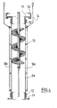
- the figure 1 shows a section of a device according to the present invention with a helical ramp (2) fixed on and wound around a central axis (3) which is here a solid rod.
- the helical ramp can be glued or welded by its base on the central rod.
- This spiral structure is wrapped by a flexible handle (1).
- This sleeve has a diameter such that the distance between the outer edge (4) of the helical ramp and the sleeve is less than the size of the particles to be loaded.
- the outer edge (4) of the ramp (2) may be in frictional contact with the inner surface of the flexible sleeve.
- the figure 2 schematically illustrates the sequence of two axis elements (6) each carrying a helical ramp (2) and separated by an intermediate element (5).
- the intermediate element (5) is connected to the axis elements (6) by a hinge means (8), for example a ring-hook system, allowing the assembly and / or disassembly easy and fast device.
- a hinge means (8) for example a ring-hook system
- the figure 3 shows a preferred embodiment of the flexible sleeve (1) used in the present invention.
- the flexible sleeve has two straight folds (7a, 7b), diametrically opposed to one another and closed at their base by a seam line (8) single or multiple.
- Each fold defines a sideband (9a, 9b) extending outwardly of the sleeve.
- One or more eyelets (10) may be provided on each sideband. These eyelets are used to hang the flexible sleeve in the part reactor (see Figure 5 ) or to secure the fixing of different modules of the device according to the invention (see Figure 4 ).
- the width of the lateral bands is not decisive but is generally between 3 and 10 cm.
- the sidebands may be doubled by a reinforcing tape (not shown), glued or secured by additional seam lines.
- the flexible sleeve is not made in one piece as on the figure 2 , but consists of several segments of flexible handle (1a) of which only one is shown here.
- This segment comprises two lateral bands (9a, 9b) formed by straight folds as explained on the figure 3 .
- a series of eyelets (10) is disposed along each sideband.
- the handle segment (la) comprises at each of its ends a flange (11) fixed to the handle segment (la) by a clamping collar (12).
- the lower flange of a first handle segment may be attached to the upper flange of the next handle segment by means of a quick fastening collar (13).
- each sideband (9a, 9b) serves to hook a safety cable (14) to prevent the lower module from stalling in case of failure of the joining system of the segments of the handle formed by the flanges (11), the clamp (12) and the quick fastening collar (13).
- figure 5 illustrates a possibility of attachment of the device of the present invention in the upper part of the reactor.
- a hopper (14) is installed in the manhole of a reactor and securely attached to the upper part thereof.
- An adapter (15) is hooked at the bottom edge of the hopper (14).
- a crossbar (16) transverse is provided in the adapter.
- the flexible sleeve (1) is secured by a clamp (17) to the adapter (15) and further hung by a suspension system (18) at the top of the reactor.
- the central axis (3) carrying the helical ramp (2) is hooked by a hook (19) to the crossbar (16) of the adapter (15).
- Two loading tests are successively carried out with two different sleeves whose heights are identical above the ground and equal to 16 meters.
- One of the handles is in accordance with the present invention and of the type described with reference to Figures 1 to 4 . It consists of a cylindrical sheath cotton woven having a thickness of 2 mm and an inner diameter of 140 mm. Said sleeve is formed of 8 modules of 2 m, each of these modules consisting of a flexible sheath and, inside the flexible sheath, two internal elements of equal length, that is to say a cable as an intermediate element and a hollow tube-shaped shaft element with a diameter of 35 mm, made of standard steel.
- the helical ramp supported by the hollow tube has a brush structure formed by crimping resin bristles in a U-shaped profile welded to the central metal axis.
- the intermediate elements and the axis elements equipped with helical ramps are connected in a conventional manner by their ends with carabiners.
- the pitch of the helix of the helical ramp is equal to 300 mm, which corresponds to a slope of 45 °, that is to say preferably between 10 ° and 80 °, and still more preferably between 20 ° and 80 °. ° and 60 °.
- the other handle is a cylindrical flexible sheath, with an internal diameter of 125 mm, suspended vertically, in which the balls fall in free fall.
- a metal plate simulating the bottom of the reactor is disposed 1 m from the lower end of each sleeve.
- Table 1 Number of broken or damaged balls with both types of loadings. testing Number of broken or damaged marbles % broken or damaged balls AT 0/66000 0.00 B 0/8000 0.00 VS 5/2000 0.25
- Table 2 Comparison of the results obtained with the sleeve according to the invention and the flexible sleeve known in the art testing % broken or damaged balls Handle according to the invention Flexible handle according to the state of the art AT 0.00 10.00 B 0.00 35,00 VS 0.25 22,00
- this device and method are not limited to this application, but can also be used for loading or unloading an enclosure with solid particles, such as catalyst particles, the integrity and physical qualities of which must be preserved.
Abstract
Description
La présente invention concerne un dispositif et un procédé pour le chargement d'une enceinte, notamment une enceinte de grande taille dont la hauteur peut atteindre plusieurs dizaines de mètres, avec des particules solides dont il est nécessaire de conserver l'intégrité physique.The present invention relates to a device and a method for charging an enclosure, in particular a large enclosure whose height can reach several tens of meters, with solid particles whose physical integrity is necessary to maintain.
Le dispositif et le procédé selon l'invention s'appliquent plus particulièrement au chargement de réacteurs à lit fixe, de type chimique ou électrochimique, pétrolier ou pétrochimique, avec des particules solides qui peuvent se présenter sous forme de billes, de grains, de cylindres, de pastilles, de bâtonnets ou sous toute autre forme, mais qui sont de dimensions relativement faibles. Les particules solides sont en particulier des particules solides assez fragiles supportant mal une chute libre d'une hauteur de plusieurs mètres.The device and the process according to the invention more particularly apply to the loading of fixed-bed reactors, of chemical or electrochemical, petroleum or petrochemical type, with solid particles which can be in the form of beads, grains or cylinders. , pellets, sticks or any other form, but which are relatively small. The solid particles are in particular relatively fragile solid particles that do not easily support a free fall of a height of several meters.
L'invention sera décrite ci-après pour des billes inertes, généralement en matériau céramique, chargées dans les réacteurs chimiques à lit catalytique fixe. La Demanderesse n'entend toutefois pas se limiter à cette application particulière car le dispositif et le procédé selon l'invention peuvent servir à l'introduction de tout autre type de matériau particulaire dans une enceinte.The invention will be described hereinafter for inert balls, generally made of ceramic material, loaded into the fixed catalytic bed chemical reactors. The Applicant does not however intend to be limited to this particular application because the device and the method according to the invention can be used for the introduction of any other type of particulate material into a chamber.
On sait que de nombreux réacteurs chimiques de grandes dimensions, par exemple d'une hauteur de 5 à 30 mètres et d'un diamètre d'environ 3 à 6 mètres, comportent en fond de capacité, au-dessous du lit de catalyseur, une couche de billes inertes, par exemple à forte concentration en alumine, de dimensions supérieures à celles des grains de catalyseur, de manière à éviter que ceux-ci ne soient évacués accidentellement par le collecteur de fond de réacteur.It is known that many large chemical reactors, for example from a height of 5 to 30 meters and a diameter of about 3 to 6 meters, have in bottom capacity, below the catalyst bed, a layer of inert balls, for example with high concentration of alumina, larger in size than those of the catalyst grains, so as to prevent them from being accidentally evacuated by the bottom collector of the reactor.
Ces billes ont un diamètre généralement inférieur à 5 cm et elles forment à la base du réacteur - ou en tout autre endroit de celui-ci, par exemple sur le plateau support de lit dans le cas d'un réacteur à double lit catalytique - un lit dont l'épaisseur peut atteindre plus de deux mètres.These balls have a diameter generally less than 5 cm and they form at the base of the reactor - or at any other place thereof, for example on the bed support plate in the case of a double catalytic bed reactor - a bed whose thickness can reach more than two meters.
Lors du chargement de ces billes, il est essentiel qu'elles soient déposées intactes au fond du réacteur ou sur le plateau support de lit, car si elles se brisent en petits fragments, elles risquent d'obturer le collecteur en sortie du réacteur ou le plateau support, provoquant ainsi une différence de pression entre l'entrée et la sortie de celui-ci, extrêmement préjudiciable au rendement du réacteur et donc in fine à l'exploitant.When loading these beads, it is essential that they be deposited intact at the bottom of the reactor or on the bed support, because if they break into small fragments, they may clog the collector at the outlet of the reactor or the support plate, thus causing a pressure difference between the inlet and the outlet thereof, extremely detrimental to the efficiency of the reactor and therefore ultimately to the operator.
Plusieurs procédés de chargement de réacteurs avec de telles billes relativement fragiles sont connus.Several methods of loading reactors with such relatively fragile beads are known.
Le chargement par des sacs ou des seaux remplis de billes, introduits individuellement dans le réacteur, puis vidés par un opérateur au fond de celui-ci, constitue une technique très sûre mais trop lente pour être normalement exploitable.The loading by bags or buckets filled with beads, introduced individually into the reactor, then emptied by an operator at the bottom of it, is a very safe technique but too slow to be normally exploitable.
Une autre technique consiste à charger les billes à l'aide d'une manche souple, d'un diamètre de 10 à 20 cm, fonctionnant en pleine charge, c'est-à-dire remplie de billes d'une extrémité à l'autre. L'opérateur distribue les billes au fond du réacteur en réglant manuellement le diamètre d'ouverture de l'extrémité inférieure de la manche tout en déplaçant celle-ci dans le réacteur. Cette méthode qui ne permet pas de garantir un taux de réussite du chargement proche des 100 % de billes intactes, présente aussi un risque d'accident important pour l'opérateur. En effet, en cas de mauvaise manipulation du système d'ouverture ou en cas de déchirure ou de décrochage de la manche souple qui supporte une charge importante, celle-ci peut tomber ou se vider totalement et brusquement, ce qui entraîne non seulement la casse des billes mais présente un risque considérable pour la sécurité de l'opérateur.Another technique is to load the balls using a flexible handle, with a diameter of 10 to 20 cm, operating at full load, that is to say filled with balls from one end to the other. other. The operator distributes the balls to the bottom of the reactor by manually adjusting the opening diameter of the lower end of the sleeve while moving it in the reactor. This method, which does not guarantee a success rate of loading close to 100% intact logs, also presents a risk of significant accident for the operator. Indeed, in case of mishandling of the opening system or in case of tearing or stalling of the flexible sleeve which supports a large load, it can fall or empty completely and suddenly, which causes not only breakage logs but presents a considerable risk to the safety of the operator.
La Demanderesse a proposé récemment, dans sa demande de brevet
La Demanderesse s'est fixé pour objectif de proposer un dispositif de chargement d'un réacteur avec des particules solides qui présente les avantages mais pas les inconvénients du dispositif décrit dans
La présente invention a par conséquent pour objet un dispositif pour introduire des particules solides dans une enceinte, notamment dans un réacteur chimique, comprenant une manche, de préférence souple et cylindrique, dans laquelle circulent du haut vers le bas lesdites particules, caractérisé par le fait qu'il comprend en outre, à l'intérieur de la manche, au moins une rampe hélicoïdale fixée sur et enroulée autour d'un axe central, ladite rampe ayant une largeur telle que la distance entre son bord extérieur et la manche souple est inférieure à la dimension des particules solides à introduire et en ce que la rampe hélicoïdale est destinée à être fixée à ladite enceinte au moyen d'un mécanisme de suspension indépendant de celui de la manche.The present invention therefore relates to a device for introducing solid particles into an enclosure, in particular into a chemical reactor, comprising a handle, preferably flexible and cylindrical, in which flow from above to below said particles, characterized by the fact it further comprises, inside the sleeve, at least one helical ramp fixed on and wound around a central axis, said ramp having a width such that the distance between its outer edge and the flexible sleeve is less than to the size of the solid particles to be introduced and in that the helical ramp is intended to be fixed to said enclosure by means of a suspension mechanism independent of that of the sleeve.
L'invention a également pour objet un procédé de chargement d'une enceinte, notamment d'un réacteur de grande taille, avec des particules solides, utilisant un tel dispositif d'introduction.The subject of the invention is also a method for charging an enclosure, in particular a large reactor, with solid particles, using such an introduction device.
Chacune des rampes hélicoïdales du dispositif de l'invention reçoit les particules solides introduites par l'extrémité supérieure de la manche, arrêtant ou interdisant la chute libre de celles-ci dans la manche en les faisant glisser ou rouler, sous l'effet de la gravité, à une vitesse qui dépend essentiellement de la pente de ladite rampe. Ce dispositif permet ainsi de limiter de manière contrôlée l'énergie cinétique conférée aux particules pendant leur descente dans la manche, en modifiant plusieurs de ses paramètres, tels que la pente de la ou des rampe(s) hélicoïdale(s) et/ou le nombre, la longueur et/ou l'espacement des zones de la manche contenant une telle rampe hélicoïdale, ou encore le pas de la ou des rampe(s) hélicoïdale(s), ces paramètres pouvant être modifiés individuellement ou en combinaison.Each of the helical ramps of the device of the invention receives the solid particles introduced by the upper end of the sleeve, stopping or preventing the free fall of these in the sleeve by dragging or rolling, under the effect of the gravity, at a speed that depends essentially on the slope of said ramp. This device thus makes it possible to limit in a controlled manner the kinetic energy imparted to the particles during their descent into the sleeve, by modifying several of its parameters, such as the slope of the helical ramp (s) and / or the number, the length and / or the spacing of the zones of the sleeve containing such a helical ramp, or the pitch of the helical ramp (s) (s), these parameters being able to be modified individually or in combination.
L'encombrement spatial du dispositif selon l'invention est déterminé par les dimensions extérieures de la manche souple enveloppant la rampe hélicoïdale, et est par conséquent identique à celui d'une manche souple classique et inférieur à celui d'une manche sinueuse ou hélicoïdale telle que décrite dans
La sécurité de fonctionnement d'un dispositif selon l'invention est considérablement augmentée par rapport à une manche souple classique car il ne fonctionne généralement pas en pleine charge ce qui réduit considérablement le poids de billes ou de particules présentes dans la manche en un instant donné. Par ailleurs, le poids des billes ou particules à charger n'est pas, comme dans le cas de la manche droite souple classique, supporté uniquement par la manche souple, mais principalement par la rampe hélicoïdale qui est fixée à la partie supérieure du réacteur par un mécanisme de suspension indépendant de celui de la manche. Les risques de déchirure ou de décrochage de la manche souple s'en trouvent ainsi considérablement réduits.The operational safety of a device according to the invention is considerably increased compared to a conventional flexible sleeve because it does not generally operate at full load which considerably reduces the weight of balls or particles present in the sleeve at a given moment. . Moreover, the weight of the balls or particles to be loaded is not, as in the case of the conventional flexible straight sleeve, supported only by the flexible sleeve, but mainly by the helical ramp which is fixed to the upper part of the reactor by a suspension mechanism independent of that of the sleeve. The risk of tearing or stalling of the flexible sleeve is thus considerably reduced.
L'axe central portant la rampe hélicoïdale peut être en un matériau rigide, par exemple un matériau métallique ou une résine thermoplastique ou thermodurcie, ou en un matériau relativement souple, par exemple une résine plastifiée ou un élastomère, ou encore un matériau composite tel qu'un caoutchouc ou une résine, renforcés par des fibres ou des textiles. Cet axe central peut avoir par exemple la forme d'un tube ou d'une tige pleine.The central axis carrying the helical ramp may be of a rigid material, for example a metallic material or a thermoplastic or thermoset resin, or a relatively flexible material, for example a plasticized resin or an elastomer, or a composite material such as rubber or resin, reinforced with fibers or textiles. This central axis may have for example the shape of a tube or a solid rod.
Les extrémités de l'axe central, ou au moins d'un élément d'axe supportant la rampe hélicoïdale, peuvent également être montées sur des pivots afin de permettre à ces dits axes de tourner librement sous le poids des billes en cours de chargement, permettant ainsi d'accélérer ledit chargement. Une automatisation de la rotation, à l'aide d'un moteur, par exemple pneumatique, peut également être envisagée.The ends of the central axis, or at least one axis element supporting the helical ramp, can also be mounted on pivots to allow these said axes to rotate freely under the weight of the balls being loaded, thus making it possible to accelerate said loading. An automation of the rotation, using a motor, for example pneumatic, can also be considered.
Dans un mode de réalisation préféré du dispositif de l'invention, l'axe central est formé par une pluralité d'éléments d'axe, souples ou rigides, qui sont articulés les uns par rapport aux autres. Cette articulation est particulièrement intéressante lorsque l'axe central est un tube ou une tige relativement rigide car elle augmente alors avantageusement la souplesse globale du dispositif et facilite sa manipulation. La conception d'un axe central en plusieurs éléments articulés les uns par rapport aux autres permet également l'ajustement de la longueur du dispositif en fonction de la hauteur du réacteur, ou le raccourcissement du dispositif au fur et à mesure que ledit réacteur est empli de particules.In a preferred embodiment of the device of the invention, the central axis is formed by a plurality of flexible or rigid axis elements, which are articulated with respect to each other. This articulation is particularly interesting when the central axis is a tube or a relatively rigid rod because it then advantageously increases the overall flexibility of the device and facilitates its handling. The design of a central axis in several elements articulated with respect to each other also allows the adjustment of the length of the device depending on the height of the reactor, or the shortening of the device as said reactor is filled. of particles.
La longueur de chacun des éléments articulés est de préférence comprise entre 5 centimètres et 5 mètres suivant le type de réacteur à charger.The length of each of the articulated elements is preferably between 5 centimeters and 5 meters depending on the type of reactor to be charged.
Dans un mode de réalisation préféré de l'invention, l'articulation de ces éléments portant la rampe hélicoïdale se fait de préférence par des éléments intermédiaires, ou éléments d'articulation. Ces éléments intermédiaires sont de préférence des éléments souples qui ne font pas obstacle à la chute libre des particules solides à l'intérieur de la manche souple, entre deux rampes hélicoïdales. Les billes ou particules à charger passent ainsi successivement et alternativement dans des zones où elles glissent ou roulent sur une rampe hélicoïdale et dans des zones où elles sont en chute libre.In a preferred embodiment of the invention, the articulation of these elements carrying the helical ramp is preferably by intermediate elements, or hinge elements. These intermediate elements are preferably flexible elements that do not prevent the free fall of the solid particles inside the flexible sleeve, between two helical ramps. The balls or particles to be charged thus pass successively and alternately in areas where they slide or roll on a helical ramp and in areas where they are in free fall.
La longueur des zones de chute libre a une influence sur la vitesse de remplissage. Plus la proportion et la longueur des zones de chute libre sont importantes, plus la vitesse de chargement est élevée. La longueur des zones de chute libre ne doit toutefois pas dépasser une valeur limite supérieure au-delà de laquelle les billes ou particules risquent de se briser ou de s'abîmer. Cette longueur maximale des éléments intermédiaires dépend, bien entendu, de la fragilité des objets à charger. La Demanderesse a constaté qu'une longueur d'éléments intermédiaires comprise entre 5 centimètres et 5 mètres, de préférence entre 0,5 et 3 mètres permettait généralement un remplissage rapide avec un taux de casse très faible des billes.The length of the free fall zones has an influence on the filling speed. The larger the proportion and the length of free fall zones, the higher the loading speed. The length of free fall zones, however, shall not exceed an upper limit value beyond which the balls or particles may break or be damaged. This maximum length of the intermediate elements depends, of course, on the fragility of the objects to be loaded. The Applicant has found that a length of intermediate elements of between 5 centimeters and 5 meters, preferably between 0.5 and 3 meters, generally allows a fast filling with a very low breakage rate of the balls.
La proportion globale de l'ensemble des zones de chute libre par rapport à la longueur totale du dispositif selon l'invention est de préférence comprise entre 20 % et 80 %, en particulier entre 40 et 70 %.The overall proportion of all the zones of free fall relative to the total length of the device according to the invention is preferably between 20% and 80%, in particular between 40 and 70%.
On peut citer à titre d'exemples des éléments intermédiaires constitués d'élingues, de cordes, de câbles, de chaînes ou de tubes souples portant à chacune de leurs extrémités des moyens appropriés permettant de les fixer aux éléments d'axe portant une rampe hélicoïdale.Examples that may be mentioned are intermediate elements consisting of slings, ropes, cables, chains or flexible tubes carrying at each of their ends appropriate means for attaching them to the axis elements carrying a helical ramp. .
La rampe hélicoïdale peut être en n'importe quel matériau d'une rigidité suffisante pour supporter le poids des billes ou particules. Il peut s'agir d'une feuille en métal, en plastique ou en caoutchouc, ou encore d'un système de type brosse.The helical ramp may be of any material of sufficient rigidity to support the weight of the balls or particles. It can be a metal sheet, plastic or rubber, or a brush-type system.
Dans un mode de réalisation préféré, la rampe hélicoïdale a une structure en brosse, le nombre et la rigidité des poils formant la brosse étant suffisants pour supporter le poids des particules à introduire lorsque le débit de chargement est maximal. Les poils peuvent être insérés dans un élément approprié, susceptible d'être collé, soudé ou fixé d'une autre manière sur l'axe central.In a preferred embodiment, the helical ramp has a brush structure, the number and rigidity of the bristles forming the brush being sufficient to support the weight of the particles to be introduced when the loading rate is maximum. The bristles can be inserted into a suitable element that can be glued, welded or otherwise attached to the central axis.
Dans un mode de réalisation particulièrement préféré, la rampe hélicoïdale est une brosse formée par sertissage de poils en résine dans un profilé en forme de U, lequel profilé est ensuite soudé sur un axe central métallique, de préférence un tube métallique.In a particularly preferred embodiment, the helical ramp is a brush formed by crimping resin bristles in a U-shaped profile, which profile is then welded to a central metal axis, preferably a metal tube.
On peut également envisager une rampe hélicoïdale de type brosse dont les poils sont pris entre deux tiges enroulées l'une par rapport à l'autre, l'hélice formée par les deux tiges enroulées constituant l'axe central d'une structure de type écouvillon.It is also possible to envisage a helical ramp of the brush type whose bristles are caught between two rods wound with respect to each other, the helix formed by the two wound rods constituting the central axis of a swab-type structure. .
La rampe hélicoïdale du dispositif selon la présente invention est de préférence une hélice simple, mais on peut également envisager des hélices doubles ou multiples. Le pas de vis, qui détermine la pente de la rampe et par conséquent la vitesse de roulement ou de glissement des particules, est de préférence compris entre 5 et 100 cm, de préférence entre 15 et 80 cm.The helical ramp of the device according to the present invention is preferably a single helix, but it is also possible to envisage double or multiple helices. The pitch, which determines the slope of the ramp and therefore the speed of rolling or sliding particles, is preferably between 5 and 100 cm, preferably between 15 and 80 cm.
Pour que la rampe puisse amortir la chute des particules et ralentir efficacement la descente de celles-ci dans la manche, il est essentiel que les particules ne puissent pas tomber par-dessus le bord extérieur de la rampe hélicoïdale. Pour cela, le bord extérieur de celle-ci est de préférence en contact avec la manche souple. Lorsque les particules ont une taille relativement importante, par exemple de l'ordre de quelques centimètres, on peut tolérer un certain écart entre le bord extérieur et la manche mais, comme il a déjà été indiqué, cette distance doit être significativement inférieure à la dimension moyenne des particules pour empêcher celles-ci de tomber par-dessus le bord de la rampe.In order for the boom to dampen the fall of the particles and effectively slow the descent of the particles into the sleeve, it is essential that the particles can not fall over the outer edge of the helical ramp. For this, the outer edge thereof is preferably in contact with the flexible sleeve. When the particles have a relatively large size, for example of the order of a few centimeters, we can tolerate a certain difference between the outer edge and the sleeve but, as already indicated, this distance must be significantly smaller than the dimension particles to prevent them from falling over the edge of the ramp.
La manche souple peut être constituée de n'importe quel matériau ayant une résistance mécanique suffisante pour résister à une déchirure pendant le procédé de chargement. Il peut s'agir par exemple d'un matériau textile, de préférence tricoté ou tissé, ou encore d'une feuille en matière plastique, éventuellement renforcée par des fibres ou par un matériau textile. On entend par manche « souple » dans la présente invention non seulement une manche capable de s'aplatir complètement lorsqu'elle est vide, mais également une manche semi-rigide, renforcée par des éléments annulaires rigides, placés à des intervalles réguliers et qui permettent une courbure de la manche mais empêchent l'aplatissement de celle-ci.The flexible sleeve may be made of any material having sufficient strength to withstand a tear during the loading process. It may be for example a textile material, preferably knitted or woven, or a plastic sheet, optionally reinforced with fibers or a textile material. The term "flexible" handle in the present invention not only a sleeve capable of flattening completely when empty, but also a semi-rigid sleeve, reinforced by rigid annular elements, placed at regular intervals and which allow a curvature of the sleeve but prevent the flattening thereof.
Le diamètre intérieur de la manche souple entourant les rampes hélicoïdales et les éléments intermédiaires ne dépasse pas de préférence quelques dizaines de centimètres, et est compris en particulier entre 50 et 400 mm, de préférence entre 100 et 200 mm.The inside diameter of the flexible sleeve surrounding the helical ramps and the intermediate elements preferably does not exceed a few tens of centimeters, and is in particular between 50 and 400 mm, preferably between 100 and 200 mm.
Selon un mode de réalisation préféré de l'invention, le dispositif de chargement est constitué d'un certain nombre de modules, chaque module comportant (i) un segment de manche souple et (ii) un segment intégrant un axe central portant une rampe hélicoïdale, et éventuellement (iii) un élément intermédiaire tel que décrit ci-dessus. Dans un tel module, la longueur d'un segment de manche souple (i) est de préférence sensiblement identique à la longueur du segment comportant un axe central (ii) ou à la longueur globale du segment comportant un axe central (ii) et de l'élément intermédiaire (iii).According to a preferred embodiment of the invention, the loading device consists of a number of modules, each module comprising (i) a flexible handle segment and (ii) a segment incorporating a central axis carrying a helical ramp. and optionally (iii) an intermediate element as described above. In such a module, the length of a flexible handle segment (i) is preferably substantially the same as the length of the segment having a central axis (ii) or the overall length of the segment having a central axis (ii) and the intermediate element (iii).
Les différents modules sont fixés les uns aux autres à la fois par enchaînement des éléments internes (axe central avec rampe hélicoïdale et élément intermédiaire) et par jonction des extrémités des segments de manche souple. Des moyens de fixation et de jonction appropriés sont connus dans la technique et l'homme du métier n'aura pas de mal à choisir ceux qui conviennent. Les éléments internes peuvent être reliés par exemple par des systèmes d'accrochage appropriés et les segments de manche souple par exemple par des colliers réunissant des brides prévues aux extrémités de chacun des segments de manche souple.The various modules are attached to each other both by sequencing the internal elements (central axis with helical ramp and intermediate element) and by joining the ends of the flexible handle segments. Suitable fastening and joining means are known in the art and those skilled in the art will have no difficulty in choosing the proper ones. The internal elements may be connected for example by appropriate fastening systems and the flexible handle segments for example by collars joining flanges provided at the ends of each of the flexible handle segments.
Dans un mode de réalisation préféré du dispositif de la présente invention, la manche souple (ou un segment de manche souple) comporte, sur une partie ou sur la totalité de sa longueur, deux plis droits, diamétralement opposés l'un à l'autre, fermés à leur base par une ligne de couture, chaque pli définissant une bande s'étendant radialement vers l'extérieur de la manche. Les bandes latérales crées ainsi de chaque côté de la manche facilitent la préhension de la manche et servent en outre à l'insertion de moyens de fixation supplémentaires, tels que des oeillets. De tels moyens de fixation supplémentaires ne devraient en effet pas être situés dans la manche souple elle-même car cela augmenterait le risque de déchirure de celle-ci.In a preferred embodiment of the device of the present invention, the flexible sleeve (or a flexible sleeve segment) comprises, over part or all of its length, two straight folds, diametrically opposite one another , closed at their base by a seam line, each fold defining a band extending radially outwardly of the sleeve. The side bands thus created on each side of the sleeve facilitate gripping of the sleeve and are also used for the insertion of additional fastening means, such as eyelets. Such additional fastening means should indeed not be located in the flexible sleeve itself as this would increase the risk of tearing thereof.
Le dispositif de chargement selon la présente invention est utilisé dans un procédé de chargement de particules solides dans des enceintes de grande taille.The loading device according to the present invention is used in a method of loading solid particles into large enclosures.
Ce procédé comprend
- (a) la fixation dudit dispositif par son extrémité supérieure au niveau d'une ouverture (trou d'homme) dans la partie supérieure de l'enceinte, la rampe hélicoïdale étant fixée à la partie supérieure de l'enceinte par un mécanisme de suspension indépendant de celui de la manche,
- (b) l'introduction des particules solides par l'extrémité supérieure dudit dispositif.
- (a) fixing said device by its upper end at an opening (manhole) in the upper part of the enclosure, the helical ramp being fixed to the upper part of the enclosure by a suspension mechanism independent of that of the sleeve,
- (b) introducing solid particles through the upper end of said device.
L'enceinte est de préférence un réacteur, généralement un réacteur cylindrique d'une hauteur comprise entre 15 et 30 mètres et d'un diamètre compris entre 3 et 4 mètres. Pour le chargement d'un tel réacteur, il est nécessaire qu'un opérateur se trouve au fond du réacteur à l'extrémité inférieure du dispositif de chargement, afin de répartir les particules sortant par l'extrémité inférieure dudit dispositif sur toute la surface du fond de l'enceinte ou du front de chargement.The enclosure is preferably a reactor, generally a cylindrical reactor with a height of between 15 and 30 meters and a diameter of between 3 and 4 meters. For the loading of such a reactor, it is necessary for an operator to be at the bottom of the reactor at the lower end of the loading device, in order to distribute the particles leaving through the lower end of said device over the entire surface of the reactor. bottom of the enclosure or front of loading.
Le réacteur peut toutefois être également un réacteur multi-tubes constitué d'une pluralité de tubes verticaux ayant chacun un diamètre similaire. Dans un mode de réalisation préféré du procédé de chargement d'un tel réacteur, le dispositif de remplissage est utilisé sans la manche souple entourant les éléments internes (axe central avec rampe hélicoïdale et élément intermédiaire), autrement dit les rampes hélicoïdales fixées sur et enroulées autour d'un axe central, ainsi que les éléments intermédiaires, sont introduits directement dans les tubes du réacteurs dont les parois remplissent alors la fonction de la manche souple, absente dans ce mode de réalisation, consistant à empêcher les billes ou particules de tomber par-dessus le bord extérieur de la rampe hélicoïdale. La largeur de la rampe hélicoïdale sera de préférence choisie de manière à ce que la distance entre le bord extérieur de la rampe et la paroi du réacteur soit inférieure à la dimension des particules solides à introduire.The reactor may, however, also be a multi-tube reactor consisting of a plurality of vertical tubes each having a similar diameter. In a preferred embodiment of the method of loading such a reactor, the filling device is used without the flexible sleeve surrounding the internal elements (central axis with helical ramp and intermediate element), that is to say the helical ramps fixed on and wound around a central axis, as well as the intermediate elements, are introduced directly into the tubes of the reactor whose walls then fulfill the function of the flexible sleeve, absent in this embodiment, consisting in preventing the balls or particles from falling by above the outer edge of the helical ramp. The width of the helical ramp will preferably be chosen so that the distance between the outer edge of the ramp and the reactor wall is less than the size of the solid particles to be introduced.
L'invention est maintenant décrite en référence aux dessins annexés, non limitatifs, dans lesquels :
- la
figure 1 est une vue en perspective d'un tronçon d'une rampe hélicoïdale d'un dispositif selon l'invention entourée d'une manche souple représentée en coupe ; - la
figure 2 est une vue schématique d'un mode de réalisation préféré du dispositif selon l'invention avec deux rampes hélicoïdales, - la
figure 3 est une vue en perspective d'un mode de réalisation préféré d'une manche souple utilisée dans le dispositif selon l'invention ; - la
figure 4 est une vue en coupe d'un module d'un dispositif de chargement selon l'invention, et - la
figure 5 est une vue en coupe montrant l'accrochage d'un dispositif selon l'invention dans la partie supérieure de l'enceinte.
- the
figure 1 is a perspective view of a section of a helical ramp of a device according to the invention surrounded by a flexible sleeve shown in section; - the
figure 2 is a schematic view of a preferred embodiment of the device according to the invention with two helical ramps, - the
figure 3 is a perspective view of a preferred embodiment of a flexible sleeve used in the device according to the invention; - the
figure 4 is a sectional view of a module of a loading device according to the invention, and - the
figure 5 is a sectional view showing the attachment of a device according to the invention in the upper part of the enclosure.
La
La
La
Sur la
Enfin, la
Deux essais de chargement sont successivement réalisés avec deux manches différentes dont les hauteurs sont identiques au-dessus du sol et égales à 16 mètres.Two loading tests are successively carried out with two different sleeves whose heights are identical above the ground and equal to 16 meters.
L'une des manches est conforme à la présente invention et du type décrit en référence aux
Le pas de l'hélice de la rampe hélicoïdale est égal à 300 mm, ce qui correspond à une pente de 45°, c'est à dire compris de préférence entre 10° et 80°, et de façon encore plus préférée, entre 20° et 60°.The pitch of the helix of the helical ramp is equal to 300 mm, which corresponds to a slope of 45 °, that is to say preferably between 10 ° and 80 °, and still more preferably between 20 ° and 80 °. ° and 60 °.
L'autre manche est une gaine cylindrique souple, d'un diamètre interne de 125 mm, suspendue à la verticale, dans laquelle on laisse tomber les billes en chute libre.The other handle is a cylindrical flexible sheath, with an internal diameter of 125 mm, suspended vertically, in which the balls fall in free fall.
On utilise pour ces essais des billes inertes en alumine fabriquées par la société allemande Vereinigte Füllkörper Fabriken GmbH et commercialisées en France sous l'appellation Duranit. Ces billes ont les diamètres suivants :
- 6,35 mm (1/4 pouce) : essais désignés par A ci-dessous ;
- 12, 67 mm (1/2 pouce) : essais désignés par B ci-dessous ;
- 19,05 mm (3/4 pouce) : essais désignés par C ci-dessous ;
- 6.35 mm (1/4 inch): tests designated by A below;
- 12, 67 mm (1/2 inch): tests designated by B below;
- 19.05 mm (3/4 inch): tests designated C below;
Une plaque métallique simulant le fond du réacteur est disposée à 1 m de l'extrémité inférieure de chaque manche.A metal plate simulating the bottom of the reactor is disposed 1 m from the lower end of each sleeve.
Dans les essais d'impacts, la masse des billes utilisées est la suivante :
- essais A , 25 kg
- essais B , 25 kg
- essais C, 10 kg
- tests A, 25 kg
- tests B, 25 kg
- C tests, 10 kg
On constate qu'alors que, dans tous les essais, le pourcentage des billes intactes est de quasiment 100% avec la manche conforme à l'invention, il varie entre 65 % et 90% avec la manche souple selon l'état de la technique.It is found that, in all tests, the percentage of intact beads is almost 100% with the sleeve according to the invention, it varies between 65% and 90% with the flexible sleeve according to the state of the art. .
Ceci s'explique essentiellement par la différence entre les vitesses d'évacuation des billes hors des deux manches, cette vitesse étant seulement d'environ 3,1 m/s avec la manche droite conforme à l'invention, pour les billes d'un diamètre de 19,05 mm (3/4 pouce), alors qu'elle est de 6,5 m/s avec la manche souple selon l'état de la technique, disposée verticalement.This is essentially explained by the difference between the speeds of discharge of the balls out of the two sleeves, this speed being only about 3.1 m / s with the right sleeve according to the invention, for the balls of a diameter of 19.05 mm (3/4 inch), while it is 6.5 m / s with the flexible sleeve according to the state of the art, arranged vertically.
Ces résultats illustrent clairement l'avantage que présentent le dispositif et le procédé conformes à l'invention pour le chargement de la partie de fond d'un réacteur chimique, ou d'un plateau support de lit, avec des billes inertes.These results clearly illustrate the advantage of the device and method according to the invention for the loading of the bottom portion of a chemical reactor, or a bed support tray, with inert balls.
Comme indiqué ci-dessus, ce dispositif et ce procédé ne sont toutefois pas limités à cette application, mais peuvent également être utilisés pour le chargement ou le déchargement d'une enceinte avec des particules solides, telles des particules de catalyseur, dont il est nécessaire de préserver l'intégrité et les qualités physiques.As indicated above, this device and method are not limited to this application, but can also be used for loading or unloading an enclosure with solid particles, such as catalyst particles, the integrity and physical qualities of which must be preserved.
Claims (16)
Priority Applications (1)
| Application Number | Priority Date | Filing Date | Title |
|---|---|---|---|
| PL08006670T PL1939115T3 (en) | 2004-08-13 | 2005-08-05 | Device for loading an enclosure with solid particles and method using this device |
Applications Claiming Priority (2)
| Application Number | Priority Date | Filing Date | Title |
|---|---|---|---|
| FR0408875A FR2874212B1 (en) | 2004-08-13 | 2004-08-13 | DEVICE FOR LOADING AN ENCLOSURE WITH SOLID PARTICLES AND METHOD USING THE DEVICE |
| EP05796259A EP1781557A1 (en) | 2004-08-13 | 2005-08-05 | Device for loading a vessel with solid particles and method using said device |
Related Parent Applications (2)
| Application Number | Title | Priority Date | Filing Date |
|---|---|---|---|
| EP05796259.9 Division | 2005-08-05 | ||
| EP05796259A Division EP1781557A1 (en) | 2004-08-13 | 2005-08-05 | Device for loading a vessel with solid particles and method using said device |
Publications (3)
| Publication Number | Publication Date |
|---|---|
| EP1939115A2 true EP1939115A2 (en) | 2008-07-02 |
| EP1939115A3 EP1939115A3 (en) | 2008-08-13 |
| EP1939115B1 EP1939115B1 (en) | 2010-05-26 |
Family
ID=34950321
Family Applications (2)
| Application Number | Title | Priority Date | Filing Date |
|---|---|---|---|
| EP05796259A Withdrawn EP1781557A1 (en) | 2004-08-13 | 2005-08-05 | Device for loading a vessel with solid particles and method using said device |
| EP08006670A Not-in-force EP1939115B1 (en) | 2004-08-13 | 2005-08-05 | Device for loading an enclosure with solid particles and method using this device |
Family Applications Before (1)
| Application Number | Title | Priority Date | Filing Date |
|---|---|---|---|
| EP05796259A Withdrawn EP1781557A1 (en) | 2004-08-13 | 2005-08-05 | Device for loading a vessel with solid particles and method using said device |
Country Status (16)
| Country | Link |
|---|---|
| US (1) | US7828023B2 (en) |
| EP (2) | EP1781557A1 (en) |
| JP (1) | JP5345315B2 (en) |
| CN (1) | CN101006000B (en) |
| AT (1) | ATE469064T1 (en) |
| AU (1) | AU2005276360B2 (en) |
| BR (1) | BRPI0514344A (en) |
| CA (1) | CA2575950C (en) |
| DE (1) | DE602005021556D1 (en) |
| DK (1) | DK1939115T3 (en) |
| ES (1) | ES2345172T3 (en) |
| FR (1) | FR2874212B1 (en) |
| PL (1) | PL1939115T3 (en) |
| PT (1) | PT1939115E (en) |
| WO (1) | WO2006021662A1 (en) |
| ZA (1) | ZA200701161B (en) |
Cited By (4)
| Publication number | Priority date | Publication date | Assignee | Title |
|---|---|---|---|---|
| EP3015163A1 (en) | 2014-10-31 | 2016-05-04 | Petroval | Process for loading particulate material into a vertical container |
| CN105647455A (en) * | 2015-12-31 | 2016-06-08 | 佛山市金银河智能装备股份有限公司 | Continuous and automatic production line of polyurethane adhesive and production method thereof |
| CN109516369A (en) * | 2018-12-04 | 2019-03-26 | 内蒙古工业大学 | A kind of material drop buffering mechanism |
| CN109607034A (en) * | 2018-12-29 | 2019-04-12 | 清华大学 | A kind of round drop buffering mechanism |
Families Citing this family (24)
| Publication number | Priority date | Publication date | Assignee | Title |
|---|---|---|---|---|
| GB0520088D0 (en) * | 2005-10-04 | 2005-11-09 | Johnson Matthey Plc | Catalyst loading apparatus |
| EP1927395B1 (en) * | 2006-12-01 | 2009-08-12 | Haldor Topsoe A/S | Apparatus for loading particulate catalytic material and loading method |
| BRPI0813997B1 (en) * | 2007-07-05 | 2017-07-04 | Saudi Basic Industries Corporation | PANEL REACTOR FOR CATALYTIC PROCESSES |
| US9156574B2 (en) * | 2007-09-28 | 2015-10-13 | Han-Tek, Inc. | Apparatus for and method of filling container with similar articles |
| US20090089184A1 (en) * | 2007-09-28 | 2009-04-02 | Embarq Holdings Company, Llc | Content portal for media distribution |
| NL1034894C2 (en) * | 2008-01-08 | 2009-07-13 | Unidense Technology Gmbh | Container e.g. electrochemical type reactor, filling device, has channel vertically and downwardly extending inside container, and braking systems fitted in channel to reduce velocity of particles |
| US9138709B2 (en) | 2010-05-24 | 2015-09-22 | Extundo Incorporated | Device and method for dispensing pellets |
| US9149778B2 (en) | 2010-05-24 | 2015-10-06 | Extundo Incorporated | Device and method for dispensing catalyst pellets |
| MY161984A (en) | 2010-05-24 | 2017-05-31 | Extundo Incorporated | Device for loading catalyst into a reactor vessel |
| FR2969587B1 (en) * | 2010-12-27 | 2013-01-04 | Total Raffinage Marketing | ALLOY DEVICE FOR LOADING SOLID PARTICLES |
| US9127425B2 (en) * | 2013-03-14 | 2015-09-08 | Meyer Products, Llc | Granular spreader assembly |
| FR2996783B1 (en) * | 2012-10-17 | 2014-11-21 | IFP Energies Nouvelles | CATALYST DENSE LOADING SYSTEM IN BAIONNETTE TUBES FOR VAPOREFORMING EXCHANGER REACTOR USING REMOVABLE HELICOIDAL ELEMENTS |
| FR2996782B1 (en) * | 2012-10-17 | 2015-10-16 | IFP Energies Nouvelles | CATALYST DENSE LOADING SYSTEM IN BAIONNETTE TUBES FOR VAPOREFORMING EXCHANGER REACTOR USING REMOVABLE DEFLECTORS |
| WO2015113064A1 (en) * | 2014-01-27 | 2015-07-30 | Brush Solutions, LLC | Scrubber system |
| CN105173780A (en) * | 2015-10-20 | 2015-12-23 | 北京首钢国际工程技术有限公司 | Rotary chute feeding device for storage bin |
| DK201500657A1 (en) * | 2015-10-23 | 2016-09-05 | Haldor Topsoe As | Catalyst Loading Method and Apparatus |
| DK3408017T3 (en) * | 2016-01-28 | 2024-02-26 | T I M E Service Catalyst Handling Gmbh | APPARATUS AND METHOD FOR FILLING A PIPE WITH PARTICULAR MATERIAL |
| CN106053332B (en) * | 2016-06-15 | 2018-12-04 | 浙江海洋大学 | Flexible fiber insertion apparatus |
| CN107521964A (en) * | 2017-08-25 | 2017-12-29 | 浙江羿阳太阳能科技有限公司 | A kind of silicon fragment high-efficiency collecting device |
| CN108046396A (en) * | 2017-12-25 | 2018-05-18 | 大连理工大学 | A kind of pipeline reactor for absorption and coagulation |
| CN113631255A (en) * | 2019-03-29 | 2021-11-09 | 三菱化学株式会社 | Method for filling granular material |
| WO2020205196A1 (en) * | 2019-04-01 | 2020-10-08 | Exxonmobil Research And Engineering Company | Methods and systems for sock-loading fixed bed reactors |
| CN111701541B (en) * | 2020-06-19 | 2021-03-09 | 宁波巨化化工科技有限公司 | Catalytic auxiliary device for gas-phase aldehyde hydrogenation reactor |
| CN117303021B (en) * | 2023-11-01 | 2024-03-29 | 青岛汇君环境能源工程有限公司 | Anti-drop's solid waste conveyor |
Citations (1)
| Publication number | Priority date | Publication date | Assignee | Title |
|---|---|---|---|---|
| FR2829107A1 (en) | 2001-08-31 | 2003-03-07 | Totalfinaelf France | Procedure for loading a vessel, in particular a chemical reactor, with inert or catalytic solid particles using a sleeve to channel the particles to the level to be loaded at the bottom end |
Family Cites Families (16)
| Publication number | Priority date | Publication date | Assignee | Title |
|---|---|---|---|---|
| US96455A (en) * | 1869-11-02 | Improvement in packing-augers and spiral conveyers | ||
| GB1393179A (en) * | 1972-04-19 | 1975-05-07 | Tickhill Eng Co Ltd | Handling means for articles |
| JPS523579A (en) * | 1975-06-27 | 1977-01-12 | Sumitomo Chem Co Ltd | Method of packing |
| FR2412627A1 (en) * | 1977-12-22 | 1979-07-20 | Rhone Poulenc Textile | METHOD AND DEVICE FOR OBTAINING DOUBLE-COMPONENT YARNS |
| DE4001121A1 (en) | 1990-01-17 | 1991-07-18 | Lange Dietrich | Screw conveyor for moving powder materials - has bristles on screw threads to clean inside of pipe |
| JPH0531351A (en) * | 1991-07-29 | 1993-02-09 | Mitsubishi Rayon Co Ltd | Catalyst packing method |
| NO175579B1 (en) * | 1991-12-20 | 1994-11-03 | Unidense Technology Gmbh | Method and apparatus for loading particulate material into vertical rudders |
| FR2686964B1 (en) * | 1992-01-30 | 1998-10-30 | Anhydride Carbonique Ind | APPARATUS FOR THE CONTINUOUS CRYOGENIC COOLING OF PARTICULATE PRODUCTS WITH A PASTY OR SOLID CHARACTER. |
| CN1098999A (en) * | 1993-08-18 | 1995-02-22 | 马壮 | Mine sealing conveyer |
| CA2131262A1 (en) * | 1993-09-07 | 1995-03-08 | Shuji Morimoto | Device for transferring solid articles |
| JPH07309411A (en) * | 1993-09-07 | 1995-11-28 | Takeda Chem Ind Ltd | Solid material carrying device |
| JP2000237577A (en) * | 1998-12-25 | 2000-09-05 | Toyo Eng Corp | Catalyst packing method and device therefor |
| EP1283070B1 (en) | 2001-08-07 | 2004-06-02 | Haldor Topsoe A/S | Catalyst loading method and apparatus |
| NO317083B1 (en) * | 2002-09-27 | 2004-08-02 | Catalyst Services Inc | Method of loading particulate matter into vertical rudders |
| CA2534865C (en) * | 2003-04-24 | 2012-01-10 | Cat Tech, Inc. | Method and apparatus for loading catalyst |
| JP2008534259A (en) * | 2005-03-25 | 2008-08-28 | キャタリスト・サービシーズ・インコーポレイテッド | Particle packing apparatus and method for filling a tube with catalyst and / or other particles |
-
2004
- 2004-08-13 FR FR0408875A patent/FR2874212B1/en not_active Expired - Fee Related
-
2005
- 2005-08-05 CA CA2575950A patent/CA2575950C/en not_active Expired - Fee Related
- 2005-08-05 AU AU2005276360A patent/AU2005276360B2/en not_active Ceased
- 2005-08-05 US US11/660,141 patent/US7828023B2/en not_active Expired - Fee Related
- 2005-08-05 DE DE602005021556T patent/DE602005021556D1/en active Active
- 2005-08-05 BR BRPI0514344-6A patent/BRPI0514344A/en not_active IP Right Cessation
- 2005-08-05 WO PCT/FR2005/002035 patent/WO2006021662A1/en not_active Application Discontinuation
- 2005-08-05 DK DK08006670.7T patent/DK1939115T3/en active
- 2005-08-05 ES ES08006670T patent/ES2345172T3/en active Active
- 2005-08-05 EP EP05796259A patent/EP1781557A1/en not_active Withdrawn
- 2005-08-05 CN CN2005800275107A patent/CN101006000B/en not_active Expired - Fee Related
- 2005-08-05 AT AT08006670T patent/ATE469064T1/en active
- 2005-08-05 PT PT08006670T patent/PT1939115E/en unknown
- 2005-08-05 PL PL08006670T patent/PL1939115T3/en unknown
- 2005-08-05 EP EP08006670A patent/EP1939115B1/en not_active Not-in-force
- 2005-08-05 JP JP2007525321A patent/JP5345315B2/en not_active Expired - Fee Related
-
2007
- 2007-02-08 ZA ZA200701161A patent/ZA200701161B/en unknown
Patent Citations (1)
| Publication number | Priority date | Publication date | Assignee | Title |
|---|---|---|---|---|
| FR2829107A1 (en) | 2001-08-31 | 2003-03-07 | Totalfinaelf France | Procedure for loading a vessel, in particular a chemical reactor, with inert or catalytic solid particles using a sleeve to channel the particles to the level to be loaded at the bottom end |
Cited By (8)
| Publication number | Priority date | Publication date | Assignee | Title |
|---|---|---|---|---|
| EP3015163A1 (en) | 2014-10-31 | 2016-05-04 | Petroval | Process for loading particulate material into a vertical container |
| US9669372B2 (en) | 2014-10-31 | 2017-06-06 | Petroval | Process for loading ceramic spheres into a vertical reactor |
| CN105647455A (en) * | 2015-12-31 | 2016-06-08 | 佛山市金银河智能装备股份有限公司 | Continuous and automatic production line of polyurethane adhesive and production method thereof |
| CN105647455B (en) * | 2015-12-31 | 2018-10-02 | 佛山市金银河智能装备股份有限公司 | A kind of polyurethane glue stick serial automatic production line and production method |
| CN109516369A (en) * | 2018-12-04 | 2019-03-26 | 内蒙古工业大学 | A kind of material drop buffering mechanism |
| CN109607034A (en) * | 2018-12-29 | 2019-04-12 | 清华大学 | A kind of round drop buffering mechanism |
| CN109607034B (en) * | 2018-12-29 | 2019-11-22 | 清华大学 | A kind of round drop buffering mechanism |
| US11661282B2 (en) | 2018-12-29 | 2023-05-30 | Tsinghua University | Spherical object falling buffer device |
Also Published As
| Publication number | Publication date |
|---|---|
| DK1939115T3 (en) | 2010-09-13 |
| JP5345315B2 (en) | 2013-11-20 |
| EP1781557A1 (en) | 2007-05-09 |
| ZA200701161B (en) | 2008-07-30 |
| CN101006000A (en) | 2007-07-25 |
| FR2874212A1 (en) | 2006-02-17 |
| ATE469064T1 (en) | 2010-06-15 |
| CN101006000B (en) | 2013-01-30 |
| US20080149215A1 (en) | 2008-06-26 |
| AU2005276360A1 (en) | 2006-03-02 |
| EP1939115B1 (en) | 2010-05-26 |
| EP1939115A3 (en) | 2008-08-13 |
| US7828023B2 (en) | 2010-11-09 |
| WO2006021662A1 (en) | 2006-03-02 |
| BRPI0514344A (en) | 2008-06-10 |
| DE602005021556D1 (en) | 2010-07-08 |
| AU2005276360B2 (en) | 2010-07-29 |
| JP2008509002A (en) | 2008-03-27 |
| CA2575950C (en) | 2012-10-09 |
| ES2345172T3 (en) | 2010-09-16 |
| PT1939115E (en) | 2010-07-26 |
| PL1939115T3 (en) | 2010-10-29 |
| FR2874212B1 (en) | 2008-02-01 |
| CA2575950A1 (en) | 2006-03-02 |
Similar Documents
| Publication | Publication Date | Title |
|---|---|---|
| EP1939115B1 (en) | Device for loading an enclosure with solid particles and method using this device | |
| CA2203727C (en) | Process and apparatus for homogeneous charging of solid catalyst particles in a tubular reactor | |
| EP1776302B1 (en) | Device and method for loading a chamber with a divided solid | |
| EP0007854A1 (en) | Device for the distribution of bulk material in an enclosure | |
| EP2029463B1 (en) | Device and method for loading solid particles into a chamber | |
| FR2740123A1 (en) | METHOD AND DEVICE FOR THE UNIFORM DISTRIBUTION OF A SOLID IN DIVIDED FORM IN AN ENCLOSURE | |
| CA2884946A1 (en) | System for dense catalyst loading in bayonet tubes for a steam reforming reactor-exchanger, using removable helical elements | |
| EP1152819B1 (en) | Method and device for facilitating the filling of vertical tubes with the aid of a particulate material | |
| CA2884943A1 (en) | Pneumatic system for dense catalyst loading in bayonet tubes for a steam reforming reactor-exchanger | |
| CA2816938C (en) | Light-weight device for loading solid particles | |
| FR2829107A1 (en) | Procedure for loading a vessel, in particular a chemical reactor, with inert or catalytic solid particles using a sleeve to channel the particles to the level to be loaded at the bottom end | |
| WO2009080978A2 (en) | Device for conveying particles, installation and method for loading a container using the device | |
| EP0046425B1 (en) | Conveyor belt arrangement for conveying concrete | |
| EP2892810B1 (en) | Device for filling a vertical elongate container with granules, for example granules of catalyst | |
| WO2023083988A1 (en) | Installation intended to separate, in an electric field, the components of a mixture of fibres and granules using a tribocharger provided with a grating for the selective confinement of said components | |
| FR3129093A1 (en) | INSTALLATION INTENDED TO SEPARATE IN AN ELECTRICAL FIELD THE COMPONENTS OF A MIXTURE OF FIBERS AND PELLETS USING A TRIBOCHARGER PROVIDED WITH A GRID FOR SELECTIVE CONTAINMENT OF SAID COMPONENTS | |
| BE624916A (en) | ||
| FR3041619A1 (en) | CONVEYOR WITH A DEEP SELF-SUPPORTING AUGER STRIP AND USE OF SUCH A STRIP | |
| FR2802190A1 (en) | Used tires are transferred from hopper to conveyor leading to treatment device; hopper has moving vertical surface with protruding rods for lifting tires out of hopper | |
| FR2681053A1 (en) | Vibration method and device for evacuating solid products in the divided-up state from a storage volume | |
| FR2695920A1 (en) | Vibrating distributor for components - uses helical track located inside vibrating bowl to selectively deliver articles in a predetermined orientation | |
| BE401987A (en) |
Legal Events
| Date | Code | Title | Description |
|---|---|---|---|
| PUAI | Public reference made under article 153(3) epc to a published international application that has entered the european phase |
Free format text: ORIGINAL CODE: 0009012 |
|
| AC | Divisional application: reference to earlier application |
Ref document number: 1781557 Country of ref document: EP Kind code of ref document: P |
|
| AK | Designated contracting states |
Kind code of ref document: A2 Designated state(s): AT BE BG CH CY CZ DE DK EE ES FI FR GB GR HU IE IS IT LI LT LU LV MC NL PL PT RO SE SI SK TR |
|
| AX | Request for extension of the european patent |
Extension state: AL BA HR MK RS |
|
| PUAL | Search report despatched |
Free format text: ORIGINAL CODE: 0009013 |
|
| RIC1 | Information provided on ipc code assigned before grant |
Ipc: B65G 11/06 20060101ALI20080624BHEP Ipc: B65G 69/16 20060101ALI20080624BHEP Ipc: B01J 8/06 20060101ALI20080624BHEP Ipc: B65G 11/20 20060101AFI20080529BHEP Ipc: B01J 8/00 20060101ALI20080624BHEP |
|
| AK | Designated contracting states |
Kind code of ref document: A3 Designated state(s): AT BE BG CH CY CZ DE DK EE ES FI FR GB GR HU IE IS IT LI LT LU LV MC NL PL PT RO SE SI SK TR |
|
| AX | Request for extension of the european patent |
Extension state: AL BA HR MK RS |
|
| RAP1 | Party data changed (applicant data changed or rights of an application transferred) |
Owner name: TOTAL RAFFINAGE MARKETING |
|
| 17P | Request for examination filed |
Effective date: 20090117 |
|
| AKX | Designation fees paid |
Designated state(s): AT BE BG CH CY CZ DE DK EE ES FI FR GB GR HU IE IS IT LI LT LU LV MC NL PL PT RO SE SI SK TR |
|
| GRAP | Despatch of communication of intention to grant a patent |
Free format text: ORIGINAL CODE: EPIDOSNIGR1 |
|
| GRAS | Grant fee paid |
Free format text: ORIGINAL CODE: EPIDOSNIGR3 |
|
| GRAA | (expected) grant |
Free format text: ORIGINAL CODE: 0009210 |
|
| AC | Divisional application: reference to earlier application |
Ref document number: 1781557 Country of ref document: EP Kind code of ref document: P |
|
| AK | Designated contracting states |
Kind code of ref document: B1 Designated state(s): AT BE BG CH CY CZ DE DK EE ES FI FR GB GR HU IE IS IT LI LT LU LV MC NL PL PT RO SE SI SK TR |
|
| REG | Reference to a national code |
Ref country code: GB Ref legal event code: FG4D Free format text: NOT ENGLISH |
|
| REG | Reference to a national code |
Ref country code: CH Ref legal event code: EP |
|
| REG | Reference to a national code |
Ref country code: IE Ref legal event code: FG4D Free format text: LANGUAGE OF EP DOCUMENT: FRENCH |
|
| REF | Corresponds to: |
Ref document number: 602005021556 Country of ref document: DE Date of ref document: 20100708 Kind code of ref document: P |
|
| REG | Reference to a national code |
Ref country code: CH Ref legal event code: NV Representative=s name: ARNOLD & SIEDSMA AG |
|
| REG | Reference to a national code |
Ref country code: PT Ref legal event code: SC4A Free format text: AVAILABILITY OF NATIONAL TRANSLATION Effective date: 20100719 |
|
| REG | Reference to a national code |
Ref country code: RO Ref legal event code: EPE |
|
| REG | Reference to a national code |
Ref country code: NL Ref legal event code: T3 |
|
| REG | Reference to a national code |
Ref country code: GR Ref legal event code: EP Ref document number: 20100401815 Country of ref document: GR |
|
| REG | Reference to a national code |
Ref country code: DK Ref legal event code: T3 |
|
| REG | Reference to a national code |
Ref country code: SE Ref legal event code: TRGR |
|
| REG | Reference to a national code |
Ref country code: ES Ref legal event code: FG2A Ref document number: 2345172 Country of ref document: ES Kind code of ref document: T3 |
|
| REG | Reference to a national code |
Ref country code: PL Ref legal event code: T3 |
|
| PG25 | Lapsed in a contracting state [announced via postgrant information from national office to epo] |
Ref country code: SI Free format text: LAPSE BECAUSE OF FAILURE TO SUBMIT A TRANSLATION OF THE DESCRIPTION OR TO PAY THE FEE WITHIN THE PRESCRIBED TIME-LIMIT Effective date: 20100526 Ref country code: LV Free format text: LAPSE BECAUSE OF FAILURE TO SUBMIT A TRANSLATION OF THE DESCRIPTION OR TO PAY THE FEE WITHIN THE PRESCRIBED TIME-LIMIT Effective date: 20100526 Ref country code: IS Free format text: LAPSE BECAUSE OF FAILURE TO SUBMIT A TRANSLATION OF THE DESCRIPTION OR TO PAY THE FEE WITHIN THE PRESCRIBED TIME-LIMIT Effective date: 20100926 |
|
| REG | Reference to a national code |
Ref country code: SK Ref legal event code: T3 Ref document number: E 7873 Country of ref document: SK |
|
| REG | Reference to a national code |
Ref country code: HU Ref legal event code: AG4A Ref document number: E008737 Country of ref document: HU |
|
| PG25 | Lapsed in a contracting state [announced via postgrant information from national office to epo] |
Ref country code: CY Free format text: LAPSE BECAUSE OF FAILURE TO SUBMIT A TRANSLATION OF THE DESCRIPTION OR TO PAY THE FEE WITHIN THE PRESCRIBED TIME-LIMIT Effective date: 20100526 |
|
| PG25 | Lapsed in a contracting state [announced via postgrant information from national office to epo] |
Ref country code: EE Free format text: LAPSE BECAUSE OF FAILURE TO SUBMIT A TRANSLATION OF THE DESCRIPTION OR TO PAY THE FEE WITHIN THE PRESCRIBED TIME-LIMIT Effective date: 20100526 |
|
| PG25 | Lapsed in a contracting state [announced via postgrant information from national office to epo] |
Ref country code: MC Free format text: LAPSE BECAUSE OF NON-PAYMENT OF DUE FEES Effective date: 20100831 |
|
| PLBE | No opposition filed within time limit |
Free format text: ORIGINAL CODE: 0009261 |
|
| STAA | Information on the status of an ep patent application or granted ep patent |
Free format text: STATUS: NO OPPOSITION FILED WITHIN TIME LIMIT |
|
| 26N | No opposition filed |
Effective date: 20110301 |
|
| REG | Reference to a national code |
Ref country code: DE Ref legal event code: R097 Ref document number: 602005021556 Country of ref document: DE Effective date: 20110228 |
|
| PG25 | Lapsed in a contracting state [announced via postgrant information from national office to epo] |
Ref country code: LU Free format text: LAPSE BECAUSE OF NON-PAYMENT OF DUE FEES Effective date: 20100805 |
|
| PGFP | Annual fee paid to national office [announced via postgrant information from national office to epo] |
Ref country code: CH Payment date: 20140724 Year of fee payment: 10 Ref country code: NL Payment date: 20140721 Year of fee payment: 10 Ref country code: DK Payment date: 20140722 Year of fee payment: 10 Ref country code: CZ Payment date: 20140723 Year of fee payment: 10 Ref country code: FI Payment date: 20140722 Year of fee payment: 10 Ref country code: LT Payment date: 20140723 Year of fee payment: 10 Ref country code: RO Payment date: 20140801 Year of fee payment: 10 Ref country code: DE Payment date: 20140722 Year of fee payment: 10 Ref country code: GR Payment date: 20140722 Year of fee payment: 10 Ref country code: IE Payment date: 20140723 Year of fee payment: 10 Ref country code: BG Payment date: 20140722 Year of fee payment: 10 |
|
| PGFP | Annual fee paid to national office [announced via postgrant information from national office to epo] |
Ref country code: FR Payment date: 20140822 Year of fee payment: 10 Ref country code: HU Payment date: 20140813 Year of fee payment: 10 Ref country code: TR Payment date: 20140804 Year of fee payment: 10 Ref country code: GB Payment date: 20140725 Year of fee payment: 10 Ref country code: SK Payment date: 20140724 Year of fee payment: 10 Ref country code: AT Payment date: 20140722 Year of fee payment: 10 Ref country code: ES Payment date: 20140814 Year of fee payment: 10 Ref country code: PL Payment date: 20140725 Year of fee payment: 10 Ref country code: SE Payment date: 20140724 Year of fee payment: 10 |
|
| PGFP | Annual fee paid to national office [announced via postgrant information from national office to epo] |
Ref country code: PT Payment date: 20140206 Year of fee payment: 10 Ref country code: IT Payment date: 20140728 Year of fee payment: 10 |
|
| PGFP | Annual fee paid to national office [announced via postgrant information from national office to epo] |
Ref country code: BE Payment date: 20140722 Year of fee payment: 10 |
|
| REG | Reference to a national code |
Ref country code: PT Ref legal event code: MM4A Free format text: LAPSE DUE TO NON-PAYMENT OF FEES Effective date: 20160205 |
|
| REG | Reference to a national code |
Ref country code: DE Ref legal event code: R119 Ref document number: 602005021556 Country of ref document: DE |
|
| REG | Reference to a national code |
Ref country code: LT Ref legal event code: MM4D Effective date: 20150805 |
|
| REG | Reference to a national code |
Ref country code: DK Ref legal event code: EBP Effective date: 20150831 |
|
| REG | Reference to a national code |
Ref country code: SE Ref legal event code: EUG |
|
| REG | Reference to a national code |
Ref country code: CH Ref legal event code: PL |
|
| REG | Reference to a national code |
Ref country code: AT Ref legal event code: MM01 Ref document number: 469064 Country of ref document: AT Kind code of ref document: T Effective date: 20150805 |
|
| GBPC | Gb: european patent ceased through non-payment of renewal fee |
Effective date: 20150805 |
|
| PG25 | Lapsed in a contracting state [announced via postgrant information from national office to epo] |
Ref country code: IT Free format text: LAPSE BECAUSE OF NON-PAYMENT OF DUE FEES Effective date: 20150805 Ref country code: CH Free format text: LAPSE BECAUSE OF NON-PAYMENT OF DUE FEES Effective date: 20150831 Ref country code: SK Free format text: LAPSE BECAUSE OF NON-PAYMENT OF DUE FEES Effective date: 20150805 Ref country code: BG Free format text: LAPSE BECAUSE OF NON-PAYMENT OF DUE FEES Effective date: 20160331 Ref country code: CZ Free format text: LAPSE BECAUSE OF NON-PAYMENT OF DUE FEES Effective date: 20150805 Ref country code: LI Free format text: LAPSE BECAUSE OF NON-PAYMENT OF DUE FEES Effective date: 20150831 Ref country code: LT Free format text: LAPSE BECAUSE OF NON-PAYMENT OF DUE FEES Effective date: 20150805 |
|
| REG | Reference to a national code |
Ref country code: SK Ref legal event code: MM4A Ref document number: E 7873 Country of ref document: SK Effective date: 20150805 |
|
| REG | Reference to a national code |
Ref country code: NL Ref legal event code: MM Effective date: 20150901 |
|
| PG25 | Lapsed in a contracting state [announced via postgrant information from national office to epo] |
Ref country code: FI Free format text: LAPSE BECAUSE OF NON-PAYMENT OF DUE FEES Effective date: 20150805 Ref country code: HU Free format text: LAPSE BECAUSE OF NON-PAYMENT OF DUE FEES Effective date: 20150806 Ref country code: SE Free format text: LAPSE BECAUSE OF NON-PAYMENT OF DUE FEES Effective date: 20150806 Ref country code: GR Free format text: LAPSE BECAUSE OF NON-PAYMENT OF DUE FEES Effective date: 20160303 Ref country code: AT Free format text: LAPSE BECAUSE OF NON-PAYMENT OF DUE FEES Effective date: 20150805 Ref country code: RO Free format text: LAPSE BECAUSE OF NON-PAYMENT OF DUE FEES Effective date: 20150805 Ref country code: PT Free format text: LAPSE BECAUSE OF NON-PAYMENT OF DUE FEES Effective date: 20160205 |
|
| REG | Reference to a national code |
Ref country code: IE Ref legal event code: MM4A |
|
| REG | Reference to a national code |
Ref country code: FR Ref legal event code: ST Effective date: 20160429 |
|
| REG | Reference to a national code |
Ref country code: GR Ref legal event code: ML Ref document number: 20100401815 Country of ref document: GR Effective date: 20160303 |
|
| PG25 | Lapsed in a contracting state [announced via postgrant information from national office to epo] |
Ref country code: NL Free format text: LAPSE BECAUSE OF NON-PAYMENT OF DUE FEES Effective date: 20150901 |
|
| PG25 | Lapsed in a contracting state [announced via postgrant information from national office to epo] |
Ref country code: DE Free format text: LAPSE BECAUSE OF NON-PAYMENT OF DUE FEES Effective date: 20160301 Ref country code: IE Free format text: LAPSE BECAUSE OF NON-PAYMENT OF DUE FEES Effective date: 20150805 Ref country code: GB Free format text: LAPSE BECAUSE OF NON-PAYMENT OF DUE FEES Effective date: 20150805 |
|
| PG25 | Lapsed in a contracting state [announced via postgrant information from national office to epo] |
Ref country code: DK Free format text: LAPSE BECAUSE OF NON-PAYMENT OF DUE FEES Effective date: 20150831 Ref country code: FR Free format text: LAPSE BECAUSE OF NON-PAYMENT OF DUE FEES Effective date: 20150831 |
|
| REG | Reference to a national code |
Ref country code: ES Ref legal event code: FD2A Effective date: 20160927 |
|
| PG25 | Lapsed in a contracting state [announced via postgrant information from national office to epo] |
Ref country code: PL Free format text: LAPSE BECAUSE OF NON-PAYMENT OF DUE FEES Effective date: 20150805 |
|
| PG25 | Lapsed in a contracting state [announced via postgrant information from national office to epo] |
Ref country code: ES Free format text: LAPSE BECAUSE OF NON-PAYMENT OF DUE FEES Effective date: 20150806 |
|
| PG25 | Lapsed in a contracting state [announced via postgrant information from national office to epo] |
Ref country code: BE Free format text: LAPSE BECAUSE OF NON-PAYMENT OF DUE FEES Effective date: 20150831 |
|
| PG25 | Lapsed in a contracting state [announced via postgrant information from national office to epo] |
Ref country code: TR Free format text: LAPSE BECAUSE OF NON-PAYMENT OF DUE FEES Effective date: 20150805 |