EP1283070B1 - Catalyst loading method and apparatus - Google Patents
Catalyst loading method and apparatus Download PDFInfo
- Publication number
- EP1283070B1 EP1283070B1 EP02014531A EP02014531A EP1283070B1 EP 1283070 B1 EP1283070 B1 EP 1283070B1 EP 02014531 A EP02014531 A EP 02014531A EP 02014531 A EP02014531 A EP 02014531A EP 1283070 B1 EP1283070 B1 EP 1283070B1
- Authority
- EP
- European Patent Office
- Prior art keywords
- tube
- loading
- section
- formed body
- reactor
- Prior art date
- Legal status (The legal status is an assumption and is not a legal conclusion. Google has not performed a legal analysis and makes no representation as to the accuracy of the status listed.)
- Expired - Lifetime
Links
- 238000011068 loading method Methods 0.000 title claims abstract description 73
- 239000003054 catalyst Substances 0.000 title claims abstract description 28
- 239000002245 particle Substances 0.000 claims abstract description 34
- 238000000034 method Methods 0.000 claims abstract description 19
- 239000000463 material Substances 0.000 claims abstract description 9
- 230000003197 catalytic effect Effects 0.000 claims abstract description 6
- 230000015572 biosynthetic process Effects 0.000 description 4
- OKKJLVBELUTLKV-UHFFFAOYSA-N Methanol Chemical compound OC OKKJLVBELUTLKV-UHFFFAOYSA-N 0.000 description 3
- 239000011236 particulate material Substances 0.000 description 3
- QGZKDVFQNNGYKY-UHFFFAOYSA-N Ammonia Chemical compound N QGZKDVFQNNGYKY-UHFFFAOYSA-N 0.000 description 2
- UFHFLCQGNIYNRP-UHFFFAOYSA-N Hydrogen Chemical compound [H][H] UFHFLCQGNIYNRP-UHFFFAOYSA-N 0.000 description 1
- 229910021529 ammonia Inorganic materials 0.000 description 1
- 230000006378 damage Effects 0.000 description 1
- 238000013016 damping Methods 0.000 description 1
- 230000001066 destructive effect Effects 0.000 description 1
- 230000000694 effects Effects 0.000 description 1
- 229920002457 flexible plastic Polymers 0.000 description 1
- 229910052739 hydrogen Inorganic materials 0.000 description 1
- 239000001257 hydrogen Substances 0.000 description 1
- 239000002184 metal Substances 0.000 description 1
- 229920003023 plastic Polymers 0.000 description 1
- 230000002028 premature Effects 0.000 description 1
- 238000009877 rendering Methods 0.000 description 1
- 230000007306 turnover Effects 0.000 description 1
- 239000011800 void material Substances 0.000 description 1
Images
Classifications
-
- B—PERFORMING OPERATIONS; TRANSPORTING
- B01—PHYSICAL OR CHEMICAL PROCESSES OR APPARATUS IN GENERAL
- B01J—CHEMICAL OR PHYSICAL PROCESSES, e.g. CATALYSIS OR COLLOID CHEMISTRY; THEIR RELEVANT APPARATUS
- B01J19/00—Chemical, physical or physico-chemical processes in general; Their relevant apparatus
-
- B—PERFORMING OPERATIONS; TRANSPORTING
- B01—PHYSICAL OR CHEMICAL PROCESSES OR APPARATUS IN GENERAL
- B01J—CHEMICAL OR PHYSICAL PROCESSES, e.g. CATALYSIS OR COLLOID CHEMISTRY; THEIR RELEVANT APPARATUS
- B01J8/00—Chemical or physical processes in general, conducted in the presence of fluids and solid particles; Apparatus for such processes
- B01J8/0015—Feeding of the particles in the reactor; Evacuation of the particles out of the reactor
- B01J8/003—Feeding of the particles in the reactor; Evacuation of the particles out of the reactor in a downward flow
-
- B—PERFORMING OPERATIONS; TRANSPORTING
- B01—PHYSICAL OR CHEMICAL PROCESSES OR APPARATUS IN GENERAL
- B01J—CHEMICAL OR PHYSICAL PROCESSES, e.g. CATALYSIS OR COLLOID CHEMISTRY; THEIR RELEVANT APPARATUS
- B01J8/00—Chemical or physical processes in general, conducted in the presence of fluids and solid particles; Apparatus for such processes
- B01J8/02—Chemical or physical processes in general, conducted in the presence of fluids and solid particles; Apparatus for such processes with stationary particles, e.g. in fixed beds
- B01J8/06—Chemical or physical processes in general, conducted in the presence of fluids and solid particles; Apparatus for such processes with stationary particles, e.g. in fixed beds in tube reactors; the solid particles being arranged in tubes
-
- B—PERFORMING OPERATIONS; TRANSPORTING
- B01—PHYSICAL OR CHEMICAL PROCESSES OR APPARATUS IN GENERAL
- B01J—CHEMICAL OR PHYSICAL PROCESSES, e.g. CATALYSIS OR COLLOID CHEMISTRY; THEIR RELEVANT APPARATUS
- B01J2208/00—Processes carried out in the presence of solid particles; Reactors therefor
- B01J2208/00743—Feeding or discharging of solids
- B01J2208/00752—Feeding
-
- B—PERFORMING OPERATIONS; TRANSPORTING
- B01—PHYSICAL OR CHEMICAL PROCESSES OR APPARATUS IN GENERAL
- B01J—CHEMICAL OR PHYSICAL PROCESSES, e.g. CATALYSIS OR COLLOID CHEMISTRY; THEIR RELEVANT APPARATUS
- B01J2208/00—Processes carried out in the presence of solid particles; Reactors therefor
- B01J2208/00743—Feeding or discharging of solids
- B01J2208/00769—Details of feeding or discharging
- B01J2208/00778—Kinetic energy reducing devices in the flow channel
Definitions
- the invention concerns a method and an apparatus for loading particulate material in reactor tubes. More particularly, the invention relates to loading of particulate, catalytic material in reactor tubes such as tubular steam reformers being employed in ammonia, hydrogen and methanol plants.
- Loading of particulate, catalytic material in tubular reactors is conventionally performed using the sock method.
- an elongated, sock-like member made of a flexible plastic material is filled with catalyst particles, and lowered into the reactor tube with the aid of a line to which the sock is attached.
- the line is jerked, thus opening the sock and releasing the particles into the reactor.
- the invention provides a method of loading particulate catalytic material into a reactor tube, comprising providing a loading tube by connecting a number of tube sections having an outer diameter smaller than the inner diameter of the reactor tube, to a final tube length corresponding to the length of the reactor tube; introducing at the top of the loading tube a quantity of the catalyst particles to be loaded into the reactor tube, causing the catalyst particles to pass through the loading tube in a damped motion by providing dampening means within the loading tube; and successively withdrawing the loading tube from the reactor tube in a length corresponding to the loading height of the catalyst particles loaded into the reactor tube, wherein the dampening means are provided by mounting a spirally formed body on the inner wall of each tube section, the spirally formed body being formed from a rod having an arbitrarily shaped cross-section and a maximum dimension in any direction of the cross-section of 1/25 -1/2 of the diameter of the tube section, the spirally formed body in each section having a pitch, with respect to the diameter of the tube section,
- the invention further provides a loading apparatus being useful in the above loading method.
- the loading apparatus comprises a loading tube having a tube diameter to fit into a reactor tube; a top part of the loading tube being adapted to be connected to a funnel unit and a bottom part of the loading tube being provided with lifting means for withdrawal of the loading tube from the reactor tube; the loading tube consisting of separate tube sections each provided with connecting means adapted to be assembled to the loading tube when connected to each other; at least one of the tube sections being provided with dampening means to decelerate the speed of catalyst particles being passed through the loading tube, wherein the dampening means are provided by mounting a spirally formed body on the inner wall of each tube section, the spirally formed body being formed from a rod having an arbitrarily shaped cross-section and a maximum dimension in any direction of the cross-section of 1/25 -1/2 of the diameter of the tube section, the spirally formed body in each section having a pitch, with respect to the diameter of the tube section, in the interval of 2-8.
- the loading apparatus consists of a number of tube sections.
- the tube sections can be assembled and inserted in a reactor tube such as a tubular reformer to form one long loading tube.
- a reactor tube such as a tubular reformer
- each of the sections is provided with a damper in form of a spirally formed body fixed to the inner wall of the tube section.
- the connecting means used to assemble the separate tube sections to the final loading tube are preferably in form of a sliding member arranged on the outer wall of one end of a tube section.
- the ends of the tube sections are typically provided with notches fitting into one another in an interlocking manner.
- the speed of the catalyst particles is reduced as the catalyst descends in a spiral movement on the spirally formed body.
- the helical movement forces the particles to align along the spiral assuring that the particles arrive one by one and not in lumps.
- the catalyst particles At the bottom of the loading tube, the catalyst particles have the same speed, and fall a short, pre-defined distance. The result is uniform dense loading with no bridging, voids or broken catalyst particles.
- a high uniform loading density is obtained by the method without hammering on the reactor tubes.
- a uniform pressure drop and thus uniform flow across the reactor tubes is also obtained.
- the result is a reduced tendency to hot spot formation and a longer tube life.
- the apparatus of the invention consists of a number of equally sized tube sections with a spirally formed body fixed on the inner walls.
- the tube sections can be connected and inserted in the reformer tubes to form one long loading tube, as apparent from the following description with reference to the drawings.
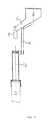
- a funnel system 2 (Fig. 1) is attached.
- System 2 is electrically vibrated by a vibrator.
- Catalyst particles being loaded into funnel 2 are continuously introduced into top tube 12 via funnel outlet 6 and gliding tube 8 mounted.
- Funnel system 2, when ready for loading is arranged on top of tube 12, such that gliding tube 8 fits into top tube 12 by sliding the system on sliding bar 10.
- the funnel system ensures the same high loading speed at all times during the loading operation.
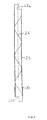
- the loading tube according to the invention is assembled by a number of tube sections 24 (Fig. 2). Each section is in a specific embodiment of the invention provided with a spirally formed body 26 as damper arranged on the inner wall of the tube section 24.
- Tube sections 24 are assembled by connecting a number of sections to a final required length of the tube.
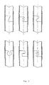
- the ends of the tube sections 24 are shaped in such a way that the end of one tube section fits into the following tube section like the components of a jig-saw puzzle, forming interlocking notches 28 (a) and (b).
- interlocking notches 28 (a) and (b) When connected in this manner, where the tube sections have coinciding tube axes, the tube sections will be locked in both axial and rotational directions relative to each other.
- the interlocking notches 28 can have various designs as exemplified in Fig. 3.
- an outer encircling sliding member 30 with an inner diameter slightly larger than the outer diameter of the tube section, is placed in the area of the connection.
- the sliding member 30 can be formed as a thin-walled tube occupying minimum space outside the tube section 24 and no space inside the tube section. The connecting means are therefore very compact.
- the damping means in the loading tube are provided by mounting a spirally formed body 26 on the inner wall of each tube section 24.
- the spirally formed body 26 is formed as a rod having an arbitrary cross section.
- the rod is in contact with the inner surface of each tube section 24 and it is formed as a spiral, making one full turn over a tube length equal to 2-8 times the tube section diameter.
- the pitch is consequently 2-8.
- the rod has a maximum dimension in any direction of its cross-section of 1/25 -1/2 of the diameter of the tube section.
- the rod can, for example, be of metal or plastic. However other materials that can be shaped as a spiral can be used.
- the speed of the catalyst particles will be reduced, as the catalyst will pass down through the loading tube on the spirally formed body. Furthermore, the vibrated funnel, the flow restriction on the funnel and the spirally formed body itself will ensure that the particles arrive singly and not in hobs to the bottom of the reactor.
- the particles enter the loading tube with a horizontal velocity component. This prevents the particles from falling freely in the loading tube. If by chance the particles enter in lumps, the particles that do not initially fall on the spirally formed body contact the sides of the tube section until they finally fall on the spirally formed body and continue in a spiral movement.
- the loading tube of the invention thus ensures a constant, non-destructive, braking effect on the particles.
- the catalyst particles At the bottom of the loading tube, the catalyst particles will thereby all have the same speed and one by one fall a short, pre-defined distance. The result is uniform dense loading with no destruction of the catalyst particles.
- the measured amount of particulate material to be loaded corresponds to a specific volume, which is proportional to the sectional area of, for instance, the tubular reformer multiplied by the height of the loading tube. This calculation allows for additional control of the loading process.
Abstract
Description
- The invention concerns a method and an apparatus for loading particulate material in reactor tubes. More particularly, the invention relates to loading of particulate, catalytic material in reactor tubes such as tubular steam reformers being employed in ammonia, hydrogen and methanol plants.
- Loading of particulate, catalytic material in tubular reactors is conventionally performed using the sock method. With this method, an elongated, sock-like member made of a flexible plastic material is filled with catalyst particles, and lowered into the reactor tube with the aid of a line to which the sock is attached. On reaching the bottom of the reactor, the line is jerked, thus opening the sock and releasing the particles into the reactor.
- When using this method, uneven and inhomogeneous loading of the reactor results in voids due to particle crushing by premature sock opening or in the formation of bridges by the particles. Void formation is undesirable because it leads to uneven temperature distribution and variations in pressure drop in the reactor. The voids can be partially removed by striking or hammering the sides of the reactor tube, causing the reactor walls to vibrate. However, this process is labour-intensive and time-consuming.
- US patent No. 5,247,979, which is incorporated herein by reference, describes a method for filling particulate material into a vertical tube using a line with a damper in the form of a series of flexible, damper brushes arranged transversely to the line. The line with damper brushes is first lowered into the vertical tube, and then the particles are poured into the tube. It is stated that quick, even and reproducible filling is attained if the line is jerked a little during the filling operation, while simultaneously being lifted up gradually as the tube is filled.
- This method, however, has several disadvantages. The falling distance of the particles from the brushes to the bottom of the tube is not under control, and the particles can also become wedged in-between the brushes and the walls of the tube, rendering the apparatus immobile in the tube. The radial distance of the brushes from the line to the walls of the tube has to correspond to the tube diameter, which means each specific tube requires its own line with brushes.
- The above-mentioned disadvantages and others associated with the various methods are solved by the method and apparatus of the invention, as will be apparent in the following.
- It is therefore an object of the invention to provide a method and an apparatus for filling particulate, catalytic material in reactor tubes such as tubular steam reformers to ensure a high catalyst density thus minimising voids and bridging of the catalyst particles.
- It is also an object of the invention to provide a loading apparatus applicable to all common catalyst types and sizes resulting in optimal loading densities with both narrow and wide tube diameters.
- It is a further object to provide a loading method which is highly automated, and therefore reduces the possibility of human errors and risk of reloading of reactor tubes.
- Finally, it is an object of the invention to provide an apparatus whereby a uniform pressure drop and uniform flow across the reactor tubes of for instance reformers is obtained, resulting in a reduced tendency to hot spot formation and a longer tube life.
- The above objects are achieved by the invention, which provides a method of loading particulate catalytic material into a reactor tube, comprising providing a loading tube by connecting a number of tube sections having an outer diameter smaller than the inner diameter of the reactor tube, to a final tube length corresponding to the length of the reactor tube; introducing at the top of the loading tube a quantity of the catalyst particles to be loaded into the reactor tube, causing the catalyst particles to pass through the loading tube in a damped motion by providing dampening means within the loading tube; and successively withdrawing the loading tube from the reactor tube in a length corresponding to the loading height of the catalyst particles loaded into the reactor tube, wherein the dampening means are provided by mounting a spirally formed body on the inner wall of each tube section, the spirally formed body being formed from a rod having an arbitrarily shaped cross-section and a maximum dimension in any direction of the cross-section of 1/25 -1/2 of the diameter of the tube section, the spirally formed body in each section having a pitch, with respect to the diameter of the tube section, in the interval of 2-8.
- The invention further provides a loading apparatus being useful in the above loading method.
- The loading apparatus according to the invention comprises a loading tube having a tube diameter to fit into a reactor tube; a top part of the loading tube being adapted to be connected to a funnel unit and a bottom part of the loading tube being provided with lifting means for withdrawal of the loading tube from the reactor tube; the loading tube consisting of separate tube sections each provided with connecting means adapted to be assembled to the loading tube when connected to each other; at least one of the tube sections being provided with dampening means to decelerate the speed of catalyst particles being passed through the loading tube, wherein the dampening means are provided by mounting a spirally formed body on the inner wall of each tube section, the spirally formed body being formed from a rod having an arbitrarily shaped cross-section and a maximum dimension in any direction of the cross-section of 1/25 -1/2 of the diameter of the tube section, the spirally formed body in each section having a pitch, with respect to the diameter of the tube section, in the interval of 2-8.
- As disclosed above, the loading apparatus consists of a number of tube sections. The tube sections can be assembled and inserted in a reactor tube such as a tubular reformer to form one long loading tube. In a specific embodiment of the invention each of the sections is provided with a damper in form of a spirally formed body fixed to the inner wall of the tube section.
- The connecting means used to assemble the separate tube sections to the final loading tube are preferably in form of a sliding member arranged on the outer wall of one end of a tube section. The ends of the tube sections are typically provided with notches fitting into one another in an interlocking manner.
- When catalyst particles are loaded through the loading tube, the speed of the catalyst particles is reduced as the catalyst descends in a spiral movement on the spirally formed body. The helical movement forces the particles to align along the spiral assuring that the particles arrive one by one and not in lumps. At the bottom of the loading tube, the catalyst particles have the same speed, and fall a short, pre-defined distance. The result is uniform dense loading with no bridging, voids or broken catalyst particles.
-
- Fig. 1 shows an apparatus according to a specific embodiment of the invention applied in a set-up ready for loading of particulate catalyst material into a reactor tube.
- Fig. 2 shows an embodiment of the invention with a spirally formed body attached to the internal surface of the tube.
- Fig. 3 shows examples of designs of the interlocking notches.
-
- With the method according to the invention, the risk of crushing of catalyst particles dropped from too high a height is eliminated. A skilled loading crew will also be able to perform the loading job significantly faster than with the conventional loading using for example the sock method.
- A high uniform loading density is obtained by the method without hammering on the reactor tubes.
- A uniform pressure drop and thus uniform flow across the reactor tubes is also obtained. The result is a reduced tendency to hot spot formation and a longer tube life.
- The apparatus of the invention consists of a number of equally sized tube sections with a spirally formed body fixed on the inner walls. The tube sections can be connected and inserted in the reformer tubes to form one long loading tube, as apparent from the following description with reference to the drawings.
- In order to control the amount of catalysts entering the loading-tube, a funnel system 2 (Fig. 1) is attached. System 2 is electrically vibrated by a vibrator. Catalyst particles being loaded into funnel 2 are continuously introduced into
top tube 12 via funnel outlet 6 and gliding tube 8 mounted. Funnel system 2, when ready for loading is arranged on top oftube 12, such that gliding tube 8 fits intotop tube 12 by sliding the system on slidingbar 10. - The funnel system ensures the same high loading speed at all times during the loading operation.
- The loading tube according to the invention is assembled by a number of tube sections 24 (Fig. 2). Each section is in a specific embodiment of the invention provided with a spirally formed
body 26 as damper arranged on the inner wall of thetube section 24. -
Tube sections 24 are assembled by connecting a number of sections to a final required length of the tube. The ends of thetube sections 24 are shaped in such a way that the end of one tube section fits into the following tube section like the components of a jig-saw puzzle, forming interlocking notches 28 (a) and (b). When connected in this manner, where the tube sections have coinciding tube axes, the tube sections will be locked in both axial and rotational directions relative to each other. - The interlocking notches 28 can have various designs as exemplified in Fig. 3.
- To secure the coinciding tube axes, an outer
encircling sliding member 30 with an inner diameter slightly larger than the outer diameter of the tube section, is placed in the area of the connection. The slidingmember 30 can be formed as a thin-walled tube occupying minimum space outside thetube section 24 and no space inside the tube section. The connecting means are therefore very compact. - The damping means in the loading tube are provided by mounting a spirally formed
body 26 on the inner wall of eachtube section 24. The spirally formedbody 26 is formed as a rod having an arbitrary cross section. The rod is in contact with the inner surface of eachtube section 24 and it is formed as a spiral, making one full turn over a tube length equal to 2-8 times the tube section diameter. The pitch is consequently 2-8. - The rod has a maximum dimension in any direction of its cross-section of 1/25 -1/2 of the diameter of the tube section.
- The rod can, for example, be of metal or plastic. However other materials that can be shaped as a spiral can be used.
- When the catalyst is loaded through the loading tube, the speed of the catalyst particles will be reduced, as the catalyst will pass down through the loading tube on the spirally formed body. Furthermore, the vibrated funnel, the flow restriction on the funnel and the spirally formed body itself will ensure that the particles arrive singly and not in hobs to the bottom of the reactor.
- The particles enter the loading tube with a horizontal velocity component. This prevents the particles from falling freely in the loading tube. If by chance the particles enter in lumps, the particles that do not initially fall on the spirally formed body contact the sides of the tube section until they finally fall on the spirally formed body and continue in a spiral movement. The loading tube of the invention thus ensures a constant, non-destructive, braking effect on the particles.
- At the bottom of the loading tube, the catalyst particles will thereby all have the same speed and one by one fall a short, pre-defined distance. The result is uniform dense loading with no destruction of the catalyst particles.
- The measured amount of particulate material to be loaded corresponds to a specific volume, which is proportional to the sectional area of, for instance, the tubular reformer multiplied by the height of the loading tube. This calculation allows for additional control of the loading process.
Claims (5)
- Method of loading particulate catalytic material into a reactor tube comprising
providing a loading tube by connecting a number of tube sections having an outer diameter smaller than the inner diameter of the reactor tube, to a final tube length corresponding to the length of the reactor tube;
introducing at the top of the loading tube a quantity of the catalyst particles to be loaded into the reactor tube, causing the catalyst particles to pass through the loading tube in a damped motion by providing dampening means within the loading tube; and
successively withdrawing the loading tube from the reactor tube in a length corresponding to the loading height of the catalyst particles loaded into the reactor tube,
wherein the dampening means are provided by mounting a spirally formed body on the inner wall of each tube section, the spirally formed body being formed from a rod having an arbitrarily shaped cross-section and a maximum dimension in any direction of the cross-section of 1/25 -1/2 of the diameter of the tube section,
the spirally formed body in each section having a pitch, with respect to the diameter of the tube section, in the interval of 2-8. - A loading apparatus for use in a loading method according to claim 1 comprising
a loading tube having a tube diameter to fit into a reactor tube;
a top part of the loading tube being adapted to be connected to a funnel unit and a bottom part of the loading tube being provided with lifting means for withdrawal of the loading tube from the reactor tube;
the loading tube consisting of separate tube sections each provided with connecting means adapted to be assembled to the loading tube when connected to each other;
at least one of the tube sections being provided with dampening means to decelerate the speed of catalyst particles being passed through the loading tube,
wherein the dampening means are provided by mounting a spirally formed body on the inner wall of each tube section, the spirally formed body being formed from a rod having an arbitrarily shaped cross-section and a maximum dimension in any direction of the cross-section of 1/25 -1/2 of the diameter of the tube section,
the spirally formed body in each section having a pitch, with respect to the diameter of the tube section, in the interval of 2-8. - Loading apparatus according to claim 2, wherein the means for connecting the tube sections comprises interlocking notches at the ends of the tube sections encircled by an outer sliding member.
- Loading apparatus according to claims 2 and 3, wherein the cross-sectional area of the spirally formed body is rectangular, circular or square.
- Loading apparatus according to claims 2-4 wherein the funnel unit is mechanised with the aid of a vibrator.
Applications Claiming Priority (2)
| Application Number | Priority Date | Filing Date | Title |
|---|---|---|---|
| DKPA200101184 | 2001-08-07 | ||
| DK200101184 | 2001-08-07 |
Publications (3)
| Publication Number | Publication Date |
|---|---|
| EP1283070A2 EP1283070A2 (en) | 2003-02-12 |
| EP1283070A3 EP1283070A3 (en) | 2003-03-19 |
| EP1283070B1 true EP1283070B1 (en) | 2004-06-02 |
Family
ID=8160655
Family Applications (1)
| Application Number | Title | Priority Date | Filing Date |
|---|---|---|---|
| EP02014531A Expired - Lifetime EP1283070B1 (en) | 2001-08-07 | 2002-07-01 | Catalyst loading method and apparatus |
Country Status (11)
| Country | Link |
|---|---|
| US (1) | US6932559B2 (en) |
| EP (1) | EP1283070B1 (en) |
| JP (1) | JP4922526B2 (en) |
| KR (1) | KR100897355B1 (en) |
| CN (1) | CN1236847C (en) |
| AT (1) | ATE268216T1 (en) |
| CA (1) | CA2396694C (en) |
| DE (1) | DE60200576T2 (en) |
| ES (1) | ES2222420T3 (en) |
| NO (1) | NO328097B1 (en) |
| ZA (1) | ZA200205437B (en) |
Families Citing this family (18)
| Publication number | Priority date | Publication date | Assignee | Title |
|---|---|---|---|---|
| NO317083B1 (en) | 2002-09-27 | 2004-08-02 | Catalyst Services Inc | Method of loading particulate matter into vertical rudders |
| AU2004234365B2 (en) | 2003-04-24 | 2009-10-22 | Cat Tech (Europe) Limited | Method and apparatus for loading catalyst |
| DE10337998A1 (en) * | 2003-08-19 | 2005-03-17 | Basf Ag | Method for filling a vertical pipe with catalyst particles |
| JP4529435B2 (en) * | 2003-12-15 | 2010-08-25 | 三菱化学株式会社 | Catalyst filling method |
| FR2874212B1 (en) * | 2004-08-13 | 2008-02-01 | Total France Sa | DEVICE FOR LOADING AN ENCLOSURE WITH SOLID PARTICLES AND METHOD USING THE DEVICE |
| WO2006104832A2 (en) * | 2005-03-25 | 2006-10-05 | Catalyst Services, Inc. | Filling tubes with catalyst and/or other particulate |
| CA2624249C (en) * | 2005-10-03 | 2014-08-05 | Tubemaster, Inc. | Device for loading chemical reactor tubes |
| US7489098B2 (en) * | 2005-10-05 | 2009-02-10 | Oshkosh Corporation | System for monitoring load and angle for mobile lift device |
| US7712490B2 (en) | 2006-03-16 | 2010-05-11 | Clean Harbors Catalyst Technologies, Llc | Method and apparatus for loading catalyst |
| US8025472B2 (en) | 2007-06-01 | 2011-09-27 | Catalyst Services, Inc. | Catalyst loading system |
| LT5866B (en) | 2010-12-30 | 2012-09-25 | Petras Kruopys | Device and method for loading of solid granules to vertical room |
| WO2014100482A1 (en) * | 2012-12-21 | 2014-06-26 | Sunedison, Inc. | Dopant funnel for loading and dispensing dopant |
| US10279330B2 (en) | 2015-04-29 | 2019-05-07 | Precision Consulting Services, LLC | Loading vertical tubes with particulate material |
| CN107855137B (en) * | 2017-11-02 | 2021-03-23 | 东南大学 | Catalyst former suitable for many specifications |
| CN108160007A (en) * | 2018-03-13 | 2018-06-15 | 洁华控股股份有限公司 | A kind of shell-and-tube reactor catalyst stirring and distribution device |
| US10576455B2 (en) * | 2018-03-22 | 2020-03-03 | Air Products And Chemicals, Inc. | Particle loading method and apparatus for a radial flow vessel |
| JP7322756B2 (en) * | 2019-03-29 | 2023-08-08 | 三菱ケミカル株式会社 | Particulate filling method |
| KR102601838B1 (en) | 2019-04-22 | 2023-11-14 | 주식회사 엘지화학 | Catalytic feeder |
Family Cites Families (19)
| Publication number | Priority date | Publication date | Assignee | Title |
|---|---|---|---|---|
| US436029A (en) * | 1890-09-09 | Traut | ||
| DE246670C (en) | ||||
| US3608751A (en) * | 1970-03-06 | 1971-09-28 | Allied Chem | Device and method for loading of vertical catalyst tubes |
| US3926290A (en) * | 1974-03-04 | 1975-12-16 | Mitsui Shipbuilding Eng | Loading chute for cargo vessel |
| JPS52140157A (en) * | 1976-05-17 | 1977-11-22 | Kobe Steel Ltd | Destruction prevention method and its device during filling/operating granular matters |
| JPS59249B2 (en) | 1976-08-10 | 1984-01-06 | 川崎重工業株式会社 | Catalyst filling device |
| US4138021A (en) * | 1977-07-25 | 1979-02-06 | Purdue Research Foundation | Ducted material handling device for top unloading of a storage receptacle |
| GB2070576A (en) * | 1980-03-03 | 1981-09-09 | New Era Steel Fabrication Co L | Construction of chutes and bunkers for material handling |
| JPS59139923A (en) * | 1983-01-28 | 1984-08-11 | Nippon Shokubai Kagaku Kogyo Co Ltd | Catalyst packing machine |
| US4701101A (en) * | 1984-03-13 | 1987-10-20 | Catalyst Technology, Inc. | Modular multi-tube catalyst loading funnel |
| NO175579B1 (en) * | 1991-12-20 | 1994-11-03 | Unidense Technology Gmbh | Method and apparatus for loading particulate material into vertical rudders |
| CA2141156A1 (en) * | 1994-01-27 | 1995-07-28 | James S. Keller | Ethylene oxide catalyst loading device |
| JPH09118411A (en) * | 1995-02-03 | 1997-05-06 | Takeda Chem Ind Ltd | Solid material charging device and container provided with the device |
| DE19713265A1 (en) | 1996-04-03 | 1997-10-30 | Oranienburger Pharmawerk Gmbh | Inclined tube passage for transporting small items e.g. pills or tablets |
| FR2747937B1 (en) * | 1996-04-26 | 1998-07-17 | Total Raffinage Distribution | METHOD AND DEVICE FOR THE HOMOGENEOUS LOADING OF PARTICLES FROM A SOLID CATALYST INTO A TUBULAR REACTOR |
| US5897282A (en) * | 1996-10-01 | 1999-04-27 | Comardo; Mathis P. | Catalytic reactor charging system and method for operation thereof |
| JPH10203617A (en) * | 1997-01-21 | 1998-08-04 | Nippon Alum Co Ltd | Buffer input device for tablet |
| JP2000237577A (en) * | 1998-12-25 | 2000-09-05 | Toyo Eng Corp | Catalyst packing method and device therefor |
| FR2789050B1 (en) * | 1999-01-28 | 2001-04-13 | Total Raffinage Distribution | METHOD AND DEVICE FOR FACILITATING THE FILLING OF VERTICAL TUBES USING A PARTICULATE MATERIAL |
-
2002
- 2002-07-01 DE DE60200576T patent/DE60200576T2/en not_active Expired - Lifetime
- 2002-07-01 AT AT02014531T patent/ATE268216T1/en not_active IP Right Cessation
- 2002-07-01 EP EP02014531A patent/EP1283070B1/en not_active Expired - Lifetime
- 2002-07-01 ES ES02014531T patent/ES2222420T3/en not_active Expired - Lifetime
- 2002-07-08 ZA ZA200205437A patent/ZA200205437B/en unknown
- 2002-07-12 US US10/193,169 patent/US6932559B2/en not_active Expired - Lifetime
- 2002-08-02 CA CA002396694A patent/CA2396694C/en not_active Expired - Lifetime
- 2002-08-06 NO NO20023706A patent/NO328097B1/en not_active IP Right Cessation
- 2002-08-06 JP JP2002228675A patent/JP4922526B2/en not_active Expired - Lifetime
- 2002-08-07 CN CNB021282684A patent/CN1236847C/en not_active Expired - Lifetime
- 2002-08-07 KR KR1020020046472A patent/KR100897355B1/en active IP Right Grant
Also Published As
| Publication number | Publication date |
|---|---|
| DE60200576T2 (en) | 2004-09-30 |
| JP4922526B2 (en) | 2012-04-25 |
| CA2396694C (en) | 2009-06-23 |
| ZA200205437B (en) | 2003-06-10 |
| NO328097B1 (en) | 2009-12-07 |
| JP2003126679A (en) | 2003-05-07 |
| US6932559B2 (en) | 2005-08-23 |
| NO20023706D0 (en) | 2002-08-06 |
| CA2396694A1 (en) | 2003-02-07 |
| EP1283070A2 (en) | 2003-02-12 |
| ES2222420T3 (en) | 2005-02-01 |
| CN1404914A (en) | 2003-03-26 |
| DE60200576D1 (en) | 2004-07-08 |
| EP1283070A3 (en) | 2003-03-19 |
| CN1236847C (en) | 2006-01-18 |
| NO20023706L (en) | 2003-02-10 |
| KR100897355B1 (en) | 2009-05-15 |
| US20030031536A1 (en) | 2003-02-13 |
| KR20030013346A (en) | 2003-02-14 |
| ATE268216T1 (en) | 2004-06-15 |
Similar Documents
| Publication | Publication Date | Title |
|---|---|---|
| EP1283070B1 (en) | Catalyst loading method and apparatus | |
| JP5228176B2 (en) | Method and apparatus for loading catalyst | |
| EP1626801B1 (en) | Method and apparatus for loading catalyst | |
| US4077530A (en) | Method for catalyst charging to tubular reactor | |
| US20010046463A1 (en) | Reactor tube loading device | |
| JP4177754B2 (en) | Method and apparatus for filling a vertical tube with particulate solid | |
| JP6349317B2 (en) | Steam reforming exchanger-a system using a removable deflector that densely charges the bayonet tube for the reactor | |
| EP1927395B1 (en) | Apparatus for loading particulate catalytic material and loading method | |
| KR20190139878A (en) | Method for Loading Pellets | |
| WO2006114241A1 (en) | Loading of catalyst particles in reaction tubes | |
| US20080292441A1 (en) | Apparatus for loading particulate catalytic material and loading method | |
| EP0061885B1 (en) | Apparatus and method for transferring solids | |
| US20080128045A1 (en) | Apparatus for loading particulate catalytic material and loading method | |
| DK201500657A1 (en) | Catalyst Loading Method and Apparatus | |
| RU2250132C2 (en) | Device of formation of the dense catalyst layers | |
| JP2002058988A (en) | Dispersion device for packing catalyst | |
| JPS6254536B2 (en) | ||
| PL123031B1 (en) | Method of filling vertically disposed tubes with granular material |
Legal Events
| Date | Code | Title | Description |
|---|---|---|---|
| PUAI | Public reference made under article 153(3) epc to a published international application that has entered the european phase |
Free format text: ORIGINAL CODE: 0009012 |
|
| PUAL | Search report despatched |
Free format text: ORIGINAL CODE: 0009013 |
|
| AK | Designated contracting states |
Designated state(s): AT BE BG CH CY CZ DE DK EE ES FI FR GB GR IE IT LI LU MC NL PT SE SK TR |
|
| AX | Request for extension of the european patent |
Extension state: AL LT LV MK RO SI |
|
| AK | Designated contracting states |
Kind code of ref document: A3 Designated state(s): AT BE BG CH CY CZ DE DK EE ES FI FR GB GR IE IT LI LU MC NL PT SE SK TR Designated state(s): AT BE BG CH CY CZ DE DK EE ES FI FR GB GR IE IT LI LU MC NL PT SE SK TR |
|
| AX | Request for extension of the european patent |
Extension state: AL LT LV MK RO SI |
|
| 17P | Request for examination filed |
Effective date: 20030919 |
|
| AKX | Designation fees paid |
Designated state(s): AT BE BG CH CY CZ DE DK EE ES FI FR GB GR IE IT LI LU MC NL PT SE SK TR |
|
| GRAP | Despatch of communication of intention to grant a patent |
Free format text: ORIGINAL CODE: EPIDOSNIGR1 |
|
| GRAS | Grant fee paid |
Free format text: ORIGINAL CODE: EPIDOSNIGR3 |
|
| GRAA | (expected) grant |
Free format text: ORIGINAL CODE: 0009210 |
|
| AK | Designated contracting states |
Kind code of ref document: B1 Designated state(s): AT BE BG CH CY CZ DE DK EE ES FI FR GB GR IE IT LI LU MC NL PT SE SK TR |
|
| PG25 | Lapsed in a contracting state [announced via postgrant information from national office to epo] |
Ref country code: CY Free format text: LAPSE BECAUSE OF FAILURE TO SUBMIT A TRANSLATION OF THE DESCRIPTION OR TO PAY THE FEE WITHIN THE PRESCRIBED TIME-LIMIT Effective date: 20040602 Ref country code: TR Free format text: LAPSE BECAUSE OF FAILURE TO SUBMIT A TRANSLATION OF THE DESCRIPTION OR TO PAY THE FEE WITHIN THE PRESCRIBED TIME-LIMIT Effective date: 20040602 Ref country code: BG Free format text: LAPSE BECAUSE OF FAILURE TO SUBMIT A TRANSLATION OF THE DESCRIPTION OR TO PAY THE FEE WITHIN THE PRESCRIBED TIME-LIMIT Effective date: 20040602 Ref country code: EE Free format text: LAPSE BECAUSE OF FAILURE TO SUBMIT A TRANSLATION OF THE DESCRIPTION OR TO PAY THE FEE WITHIN THE PRESCRIBED TIME-LIMIT Effective date: 20040602 Ref country code: FI Free format text: LAPSE BECAUSE OF FAILURE TO SUBMIT A TRANSLATION OF THE DESCRIPTION OR TO PAY THE FEE WITHIN THE PRESCRIBED TIME-LIMIT Effective date: 20040602 Ref country code: SK Free format text: LAPSE BECAUSE OF FAILURE TO SUBMIT A TRANSLATION OF THE DESCRIPTION OR TO PAY THE FEE WITHIN THE PRESCRIBED TIME-LIMIT Effective date: 20040602 Ref country code: CZ Free format text: LAPSE BECAUSE OF FAILURE TO SUBMIT A TRANSLATION OF THE DESCRIPTION OR TO PAY THE FEE WITHIN THE PRESCRIBED TIME-LIMIT Effective date: 20040602 Ref country code: AT Free format text: LAPSE BECAUSE OF FAILURE TO SUBMIT A TRANSLATION OF THE DESCRIPTION OR TO PAY THE FEE WITHIN THE PRESCRIBED TIME-LIMIT Effective date: 20040602 Ref country code: BE Free format text: LAPSE BECAUSE OF FAILURE TO SUBMIT A TRANSLATION OF THE DESCRIPTION OR TO PAY THE FEE WITHIN THE PRESCRIBED TIME-LIMIT Effective date: 20040602 |
|
| REG | Reference to a national code |
Ref country code: GB Ref legal event code: FG4D |
|
| REG | Reference to a national code |
Ref country code: CH Ref legal event code: EP |
|
| PG25 | Lapsed in a contracting state [announced via postgrant information from national office to epo] |
Ref country code: LU Free format text: LAPSE BECAUSE OF NON-PAYMENT OF DUE FEES Effective date: 20040701 Ref country code: IE Free format text: LAPSE BECAUSE OF NON-PAYMENT OF DUE FEES Effective date: 20040701 |
|
| REF | Corresponds to: |
Ref document number: 60200576 Country of ref document: DE Date of ref document: 20040708 Kind code of ref document: P |
|
| REG | Reference to a national code |
Ref country code: CH Ref legal event code: NV Representative=s name: PATENTANWALTSBUERO JEAN HUNZIKER |
|
| REG | Reference to a national code |
Ref country code: IE Ref legal event code: FG4D |
|
| PG25 | Lapsed in a contracting state [announced via postgrant information from national office to epo] |
Ref country code: MC Free format text: LAPSE BECAUSE OF NON-PAYMENT OF DUE FEES Effective date: 20040731 |
|
| PG25 | Lapsed in a contracting state [announced via postgrant information from national office to epo] |
Ref country code: DK Free format text: LAPSE BECAUSE OF FAILURE TO SUBMIT A TRANSLATION OF THE DESCRIPTION OR TO PAY THE FEE WITHIN THE PRESCRIBED TIME-LIMIT Effective date: 20040902 Ref country code: SE Free format text: LAPSE BECAUSE OF FAILURE TO SUBMIT A TRANSLATION OF THE DESCRIPTION OR TO PAY THE FEE WITHIN THE PRESCRIBED TIME-LIMIT Effective date: 20040902 Ref country code: GR Free format text: LAPSE BECAUSE OF FAILURE TO SUBMIT A TRANSLATION OF THE DESCRIPTION OR TO PAY THE FEE WITHIN THE PRESCRIBED TIME-LIMIT Effective date: 20040902 |
|
| ET | Fr: translation filed | ||
| REG | Reference to a national code |
Ref country code: ES Ref legal event code: FG2A Ref document number: 2222420 Country of ref document: ES Kind code of ref document: T3 |
|
| REG | Reference to a national code |
Ref country code: IE Ref legal event code: MM4A |
|
| PLBE | No opposition filed within time limit |
Free format text: ORIGINAL CODE: 0009261 |
|
| STAA | Information on the status of an ep patent application or granted ep patent |
Free format text: STATUS: NO OPPOSITION FILED WITHIN TIME LIMIT |
|
| 26N | No opposition filed |
Effective date: 20050303 |
|
| PG25 | Lapsed in a contracting state [announced via postgrant information from national office to epo] |
Ref country code: PT Free format text: LAPSE BECAUSE OF NON-PAYMENT OF DUE FEES Effective date: 20041102 |
|
| REG | Reference to a national code |
Ref country code: FR Ref legal event code: PLFP Year of fee payment: 15 |
|
| REG | Reference to a national code |
Ref country code: FR Ref legal event code: PLFP Year of fee payment: 16 |
|
| PGFP | Annual fee paid to national office [announced via postgrant information from national office to epo] |
Ref country code: CH Payment date: 20170727 Year of fee payment: 16 |
|
| REG | Reference to a national code |
Ref country code: FR Ref legal event code: PLFP Year of fee payment: 17 |
|
| REG | Reference to a national code |
Ref country code: CH Ref legal event code: PL |
|
| PG25 | Lapsed in a contracting state [announced via postgrant information from national office to epo] |
Ref country code: CH Free format text: LAPSE BECAUSE OF NON-PAYMENT OF DUE FEES Effective date: 20180731 Ref country code: LI Free format text: LAPSE BECAUSE OF NON-PAYMENT OF DUE FEES Effective date: 20180731 |
|
| PGFP | Annual fee paid to national office [announced via postgrant information from national office to epo] |
Ref country code: NL Payment date: 20210730 Year of fee payment: 20 |
|
| PGFP | Annual fee paid to national office [announced via postgrant information from national office to epo] |
Ref country code: FR Payment date: 20210726 Year of fee payment: 20 Ref country code: IT Payment date: 20210722 Year of fee payment: 20 |
|
| PGFP | Annual fee paid to national office [announced via postgrant information from national office to epo] |
Ref country code: GB Payment date: 20210726 Year of fee payment: 20 Ref country code: ES Payment date: 20210810 Year of fee payment: 20 Ref country code: DE Payment date: 20210928 Year of fee payment: 20 |
|
| REG | Reference to a national code |
Ref country code: DE Ref legal event code: R071 Ref document number: 60200576 Country of ref document: DE |
|
| REG | Reference to a national code |
Ref country code: NL Ref legal event code: MK Effective date: 20220630 |
|
| REG | Reference to a national code |
Ref country code: GB Ref legal event code: PE20 Expiry date: 20220630 |
|
| PG25 | Lapsed in a contracting state [announced via postgrant information from national office to epo] |
Ref country code: GB Free format text: LAPSE BECAUSE OF EXPIRATION OF PROTECTION Effective date: 20220630 |
|
| REG | Reference to a national code |
Ref country code: ES Ref legal event code: FD2A Effective date: 20220801 |
|
| PG25 | Lapsed in a contracting state [announced via postgrant information from national office to epo] |
Ref country code: ES Free format text: LAPSE BECAUSE OF EXPIRATION OF PROTECTION Effective date: 20220702 |