EP1938977A1 - Dispositif et procédé destinés à introduire au moins une bande de matière ou au moins une rame dans une plieuse - Google Patents
Dispositif et procédé destinés à introduire au moins une bande de matière ou au moins une rame dans une plieuse Download PDFInfo
- Publication number
- EP1938977A1 EP1938977A1 EP20080152822 EP08152822A EP1938977A1 EP 1938977 A1 EP1938977 A1 EP 1938977A1 EP 20080152822 EP20080152822 EP 20080152822 EP 08152822 A EP08152822 A EP 08152822A EP 1938977 A1 EP1938977 A1 EP 1938977A1
- Authority
- EP
- European Patent Office
- Prior art keywords
- guide rail
- former
- material web
- strand
- web
- Prior art date
- Legal status (The legal status is an assumption and is not a legal conclusion. Google has not performed a legal analysis and makes no representation as to the accuracy of the status listed.)
- Granted
Links
Images


Classifications
-
- B—PERFORMING OPERATIONS; TRANSPORTING
- B65—CONVEYING; PACKING; STORING; HANDLING THIN OR FILAMENTARY MATERIAL
- B65H—HANDLING THIN OR FILAMENTARY MATERIAL, e.g. SHEETS, WEBS, CABLES
- B65H45/00—Folding thin material
- B65H45/12—Folding articles or webs with application of pressure to define or form crease lines
- B65H45/28—Folding in combination with cutting
-
- B—PERFORMING OPERATIONS; TRANSPORTING
- B41—PRINTING; LINING MACHINES; TYPEWRITERS; STAMPS
- B41F—PRINTING MACHINES OR PRESSES
- B41F13/00—Common details of rotary presses or machines
- B41F13/02—Conveying or guiding webs through presses or machines
- B41F13/03—Threading webs into printing machines
-
- B—PERFORMING OPERATIONS; TRANSPORTING
- B41—PRINTING; LINING MACHINES; TYPEWRITERS; STAMPS
- B41F—PRINTING MACHINES OR PRESSES
- B41F13/00—Common details of rotary presses or machines
- B41F13/54—Auxiliary folding, cutting, collecting or depositing of sheets or webs
- B41F13/56—Folding or cutting
-
- B—PERFORMING OPERATIONS; TRANSPORTING
- B65—CONVEYING; PACKING; STORING; HANDLING THIN OR FILAMENTARY MATERIAL
- B65H—HANDLING THIN OR FILAMENTARY MATERIAL, e.g. SHEETS, WEBS, CABLES
- B65H2301/00—Handling processes for sheets or webs
- B65H2301/50—Auxiliary process performed during handling process
- B65H2301/52—Auxiliary process performed during handling process for starting
- B65H2301/522—Threading web into machine
-
- B—PERFORMING OPERATIONS; TRANSPORTING
- B65—CONVEYING; PACKING; STORING; HANDLING THIN OR FILAMENTARY MATERIAL
- B65H—HANDLING THIN OR FILAMENTARY MATERIAL, e.g. SHEETS, WEBS, CABLES
- B65H2801/00—Application field
- B65H2801/03—Image reproduction devices
- B65H2801/21—Industrial-size printers, e.g. rotary printing press
-
- Y—GENERAL TAGGING OF NEW TECHNOLOGICAL DEVELOPMENTS; GENERAL TAGGING OF CROSS-SECTIONAL TECHNOLOGIES SPANNING OVER SEVERAL SECTIONS OF THE IPC; TECHNICAL SUBJECTS COVERED BY FORMER USPC CROSS-REFERENCE ART COLLECTIONS [XRACs] AND DIGESTS
- Y10—TECHNICAL SUBJECTS COVERED BY FORMER USPC
- Y10T—TECHNICAL SUBJECTS COVERED BY FORMER US CLASSIFICATION
- Y10T83/00—Cutting
- Y10T83/081—With randomly actuated stopping means
- Y10T83/084—With stop-signal-responsive means to actuate auxiliary cutter
-
- Y—GENERAL TAGGING OF NEW TECHNOLOGICAL DEVELOPMENTS; GENERAL TAGGING OF CROSS-SECTIONAL TECHNOLOGIES SPANNING OVER SEVERAL SECTIONS OF THE IPC; TECHNICAL SUBJECTS COVERED BY FORMER USPC CROSS-REFERENCE ART COLLECTIONS [XRACs] AND DIGESTS
- Y10—TECHNICAL SUBJECTS COVERED BY FORMER USPC
- Y10T—TECHNICAL SUBJECTS COVERED BY FORMER US CLASSIFICATION
- Y10T83/00—Cutting
- Y10T83/202—With product handling means
Definitions
- the invention relates to a device and a method for drawing at least one material web or at least one web strand into a folding apparatus according to the preamble of claim 1 or 27.
- a folder such. B. off WO 00/56652 A1 comprises a superstructure, in which merged from one or more printing units paper webs combined, possibly longitudinally cut and placed over each other, at least one former, on each of which in the superstructure of one or more paper webs merged web track is folded longitudinally, and a Cross-cutting device in which the leksgefalzte web is broken down into individual products.
- the cross-cutting device is realized by a rotating knife cylinder, the blades cooperate for cutting the web track with an abutment on a gripper or folding blade.
- the grippers of this cylinder retain the products singulated by the cross-cutter on the surface of the cylinder and convey them to a transfer nip between the folding blade cylinder and a jaw cylinder where a folding blade extends out of the folding blade cylinder to move the product held thereon along a transverse centerline into a jaw to introduce the jaw cylinder and so fold across.
- EP 05 53 740 B1 known to use a holding part in the form of a rail-guided link chain piece to which the obliquely torn off leading end of the recovering web is attached.
- the rail runs next to the intended path of the web through the printing press to the superstructure of a folder.
- the DE 42 10 190 A1 discloses a cutting device with integrated switch, which is arranged between draw rollers and folding cylinders.
- the DE 101 28 821 A1 shows a device for merging paper webs during retraction.
- the US 31 25 335 A discloses a device for drawing webs of material by means of tapes.
- the EP 06 73 764 A1 discloses a device for drawing-in of printing substrate webs via turning bars, wherein partial printing substrate webs are pulled in by draw-in tips which are fastened to guide rail-running side-bow chains.
- a former assembly in which the or the former through at least one actuator to adapt to different web widths is or are transverse to the direction of the web.
- variable length guide rail piece for use as a retractor for a paper web roller chain.
- the post-published DE 10 2004 022 541 A1 shows an apparatus for drawing a web along a Leksfalztrichters.
- the DE 33 12 038 A1 discloses a device for drawing material webs in rotary printing machines by means of a Einziehbandes. In this case, the returning part of the Einziehbandes compared to the retracting part is guided on another track.
- the post-published WO 2005/092614 A2 describes a device for drawing a material web in a folding apparatus with a former, a cross-cutting device and a guide rail.
- the device has a capping device.
- the invention has for its object to provide a device and a method for drawing at least one web or at least one web strand in a folder.
- the guide rail course adapts automatically on account of the shape-variable guide rail section.
- the Einziehvorgang a material web is thus possible in any funnel position.
- the shape variable guide rail section compensates for both an angular offset of the guide rail in the direction of the machine center and a longitudinal displacement of the guide rail in the running direction of the material web, so that can be retracted in any position.
- variable-shape guide rail section in a preferred embodiment of the invention on the one hand from a variable-shape carrier strand and on the other hand composed of a carrier strand held guide elements, it is on the one hand possible to obtain the shape variability of the guide rail portion exclusively on the basis of the carrier strand and the guide elements other material, in particular to produce a relatively stiff material such as metal.
- the shape-variable carrier strand may, for example, a homogeneous strand of suitable, to some extent elastically deformable plastic or of a Rubber material, whereby in particular the curving of the guide means can be achieved, to a certain extent, a length variability.
- the guide strand comprises a plurality of seen in the longitudinal direction of the support strand substantially successively arranged support elements, adjacent support elements are coupled to each other in particular distance variable, which can advantageously be realized by adjacent support elements engage with play with each other ,
- Such a design of the invention allows a particularly high dimensional variability of the carrier strand and thus of the variable-shape guide rail portion and in particular a high length variability, which is determined primarily by the sum of the game between the adjacent support elements.
- connection between the adjacent carrier elements results when the carrier elements engage with corresponding play in openings of the respective adjacent carrier element with play or, in an alternative embodiment, coupled with each other via oppositely directed, in particular hook-shaped coupling approaches are.
- the assembly of the carrier strand from the individual carrier elements becomes particularly simple if the carrier elements formed, for example, as described above, can be brought into engagement with each other substantially perpendicularly to the longitudinal direction of the guide rail section.
- the guide elements are preferably designed pushed onto the support strand or the support elements and in a preferred embodiment of the invention it is provided that the Guide elements engage around the support elements at least in the region of the coupling, so that in this way the coupling or connection between two adjacent support members is secured by the associated guide element.
- the former is preferably displaceable parallel to the longitudinal axis of the cross cutting device.
- a section of the guide rail lying in the running direction of the web strand in front of the former should be stretchable.
- the guide rail has a formvariable guide rail section, in particular a variable length guide rail section.
- the guide rail is preferably twisted at the level of the former, preferably by about 90 °.
- the guide rail may extend to a position located on the web of material between first and second trimming devices, wherein the first trimming device may be phase-correlated and the second trimming device may be emergency-operated; beyond this position, such tools for automatic retraction of the strand are no longer required after z.
- the white waste by means of the phase-correlated Kappvorraum the useful part of the web strand in the below Phase-correlated capping device arranged emergency stop-operated Kappvorraum or arranged below the cross cutter enters without requiring a guide through the guide rail.
- the memory may in particular be formed by a further guide rail section which extends, over a curved section, away from the material web in the lateral direction and is capable of accommodating a plurality, preferably a plurality of holding parts next to one another.
- the storage device may be preceded by a separating device for separating the holding parts from their respective material webs, so that the leading sections of the material webs entrained by the holding parts do not have to be accommodated in the store if there is insufficient space for this purpose.
- the guide rail may preferably extend continuously from a reel changer of a printing unit upstream of the folder into the folding apparatus or up to the emergency stop-operated trimming device.
- At least one return-guiding rail which is different from the at least one guide rail, can be provided for returning retaining parts to the starting position. This has the significant advantage that it is independent of the rest of the operation of the system in principle At any time, it is possible to return the holding parts to their starting point via the at least one returning guide rail.
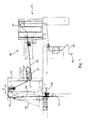
- Fig. 1 and 2 It is going on first Fig. 1 and 2 Referenced. Coming from a printing unit, not shown, in the representation of Fig. 1 from the bottom right coming web 01, z. B. Paper web 01 reaches a superstructure 03 of a folder.
- the superstructure 03 comprises a longitudinal cutter 04 for disassembling the incoming paper web 01 into a plurality of juxtaposed partial webs, a turning table 06, in which the sub-webs of the paper web 01 and possibly further, unillustrated paper webs rearranged, transversely to the direction (from right to left in Fig. 1 ) and / or turned and then superimposed. From the turning table 06, the path of the paper web 01 extends over an arrangement of compensating rollers 07 for web length compensation and traction control to a former 08.
- Forming hopper 08 and compensating rollers 07 are in a common frame 02 in the lateral direction of the Fig. 1 moveable, as in Fig. 1 indicated by the double arrow A, and further, the former 08 on the frame 02 transverse to the longitudinal direction of the incoming paper web 01 be adjustable, as shown in Fig.2 indicated by the double arrow B.
- the paper web 01 travels downwardly substantially downwards through a first capping device 11 and a second capping device 12 and then through a cross-cutting device 24 and a cross-folding device of per se known construction, not to be explained more precisely here.
- train groups 26; 27; 28 provided to guide the paper web 01 between the former 08 and cross-cutting device 24.
- a guide rail 09 which extends in the illustration Fig. 1 largely coincides with the paper web 01, in fact but is arranged substantially next to the paper web 01 at a predetermined distance.
- the guide rail 09 is used in the manner described in more detail below for drawing a paper web 01 through the machine into the folder.
- the drawing-in process is preferably carried out by the printing units associated with the web path (not shown) while they are not printing.
- the guide rail 09 extends, as in particular also from Fig. 2 recognizable along the former 08 and into the area between the first Kappvoruze 11 and the second Kappvortechnik 12, from where it is led out via a curved guide rail portion 13 laterally out of contact with a cross member 14 and there to form one or more loops Memory 16 for the below to be explained, guided in the guide rail 09 holding parts defined at which the leading end of a paper web 01 is fixed during retraction.
- the guide rail 09 preferably extends without interruption of a non-illustrated reel changer of the folder upstream, in the Fig. 1 not shown printing unit to the above-explained position.
- a separating device At the entrance of the memory 16 adjacent to the curved guide rail portion 13, a separating device, not shown, may be arranged, which releases the head portion of each passing paper web 01 of its holding part. The trackless track beyond the separator falls down freely next to the folder and is thus ejected.
- an additional return guide rail is provided, via which the holding parts are returned to their original position.
- the returning guide rail may, for example, connect to the end of the memory 16, so that the holding parts are quasi circulated. If such an additional, returning guide rail is provided, it would also be possible to dispense with a memory 16 after it allows retaining parts to be returned at any time irrespective of the respective operating state of the machine.
- the end of the guide rail 09 is, as already mentioned above, arranged between the first capping device 11, which may in particular be a phase-correlated capping device 11, and the second capping device 12, which may be an emergency stop-operated capping device 12, as hereinafter particularly with reference on Fig. 3 is explained in more detail.
- the material web 01 in particular paper web 01, carries a recurring after a certain repetition length L B processing pattern, eg. B. a printed image.
- L B processing pattern eg. B. a printed image.
- the material webs 02 or a web 05 comprising the repetitive processing pattern are cut from one or more such material webs 02 into product sections 17.
- the folding apparatus F can, as shown, in particular a transport cylinder 38, for example, designed as a cylinder 28 gripper cylinder 38 with grippers 39 and knives 41 and a cooperating with this and a folding gap 42 defining jaw cylinder 43 include.
- the transport cylinder 38 acts with a Cylinder 44, z. B. knife cylinder 44 together, the knife 45 carries, whereby the cross-cutting device 24 is formed.
- the strand 05 is cut into product sections 17 to match the recurring repeat length L B.
- suitable cut is the cross-cutting device 24 and a processing pattern applying, not shown aggregate, for. B. printing unit, synchronized in their power stroke and a distance of the web (s) from the unit to the section optionally additionally by a longitudinal register means, not shown, adjustable to an integer multiple of the repeat length L B.
- the synchronization can be done electronically by a common drive motor motor via mechanical coupling or preferably mechanically mechanically independent of each other by drive motors driven unit and cross-cutting device 24 via a so-called. Virtual master axis when driving unit and cross cutting device 24.
- the virtual master axis is shown here as part of a schematic in Fig. 3 identified machine control 18 understood.
- it can generate angular setpoint values ⁇ purely synthetically and to all drives of assemblies to be synchronized and, for example, to a drive M driving the cross-cutting device 24.
- the angular position command values ⁇ of the leading axis and thus the other drives can be synchronized via the leading axis Position of the folder F and the cross cutter 24 follow.
- the capping device 12 for spontaneously capping the strand 05, for example due to an emergency stop, arranged.
- This capping device 12 is designed to penetrate the strand 05 with a short reaction time to a corresponding command and at the same timegol meeting in an advantageous development of the strand path to the folder F out.
- can basically any capping device 12 may be provided in which a knife 31 is movable into or out of the strand path in the strand path.
- the cutting device 12 a knife 31 which is pivotally mounted on an axis 36, and is movable by pivoting in the strand path in or out of the strand path out.
- the adjusting means 32 is in this case via a control device 35 and an actuator 35, for example, designed as a valve for the pressure medium, due to a Signal N (example for emergency stop) operated.
- This signal N may come from the machine controller 18 or, for a short duration, directly from error detecting sensors.
- the Kappvortechnisch 12 a guide 33, z. B.
- the capping device 12 may have a bracket 34, which can be pivoted together with the blade 31, which supports the guiding of the strand beginning in the direction of the folding apparatus 12 when the blade 31 is deactivated.
- the remainder R is cut off as a first operational cut which, however, due to its shortened length, does not come from the gripper 39 is receivable. If the risk of a renewed disturbance caused thereby is to be avoided, then the remainder R would have to be removed from the folder F in a complex manner.
- the capping device 11 which can be controlled in accordance with the register is arranged.
- register-compliant caps are to be understood as meaning a capping of the strand 05 (or of material webs 01) at an operative cutting line S provided for the cut between two consecutive repeat lengths L B.
- the capping device 11 has a capping element 47 or knife 47, which extends perpendicular to the longitudinal extent of the strand 05 and parallel to the plane of the strand 05 and is guided movably perpendicular to the plane of the strand 05 on a linear travel.
- a displacement of the cap member 47 and thus the knife 47 is z. B. via a pressure medium-operated adjusting means 48, z.
- a hydraulic or pneumatic cylinder 48 with piston and plunger whose movement via a motion transmission mechanism 49, which may be a pivot lever mechanism 49 in particular, in the linear movement of the cap member 47 can be transferred.
- the cap member 47 or knife 47 acts with this opposite another cap element 50 and an abutment 50, z. B. designed as a counter knife 50 or cutting bar 50, together, wherein the two cap elements 47; 50 form a cutting groove when interacting.
- This counter-knife 50 is preferably arranged fixed on the other side of the strand 05, but could also be movable, in particular linearly movable or else movable instead of the first cap member 47 or knife 47.
- Actuation of the capping device 11 is phase-correlated to the cross-cutting device 24.
- the register-correct triggering of the capping device 11 for later operational cut takes place on the basis of a signal to the operational cross-cutting device 24 (z ., the folding apparatus F) relevant status information l, in particular phase information l (in short: signal l).
- this phase information I represents an angle information I of the knife cylinder 44 driven synchronously with the strand 05.
- the phase information l can advantageously directly on the knife cylinder 44 by a corresponding detection system 40, z. B.
- initiator cooperating sensor one with a knife with the cylinder 44 rotatably connected initiator cooperating sensor can be obtained.
- This initiator then stands, for example, in a fixed, exactly selected angular reference for register-compatible caps with the capping device 11, so that due to a pulse during the passage of the initiator on the sensor, the capping is carried out by the capping device 11.
- phase information l can also be derived from the leading axis of the machine control 18, since their phase position with the phase angle of the folder F, in particular the cross cutter 24, correlates in a defined manner.
- the signal of the phase information I is processed in a control device 56 and triggers the register-compliant caps by the capping device 11.
- the control device 56 can be designed as a simple actuator 56, for example as a valve for pressurizing medium. If the phase information I only represents information about instantaneous angular positions, then the control device 56 has means for determining (eg, input means) a defined desired position and for evaluating the phase information I obtained in this regard.
- the guide rail 09 used substantially over the entire guide path has, as in FIG Fig. 4 shown, a total of a U-shaped or C-shaped cross-section, in whose groove 23, in particular longitudinal groove 23 each have a chain piece 51 is guided.
- the chain piece 51 is constructed of alternating one- or two-segmented members 52; 53, of which at least one carries out of the groove 23 extending arm 19.
- two adjacent links 53 common carry an arm 19.
- Chain piece 51 and arm 19 are hereinafter also referred to as holding part 51, 19.
- a hook at the end of the arm 19 is provided to fasten, with the aid of a loop wrapped around it, the leading end 54 of a paper web 01 to be newly collected or a draw-in tip connected to the leading end 54.
- the single-segment members 52 are elastic in itself, z. B. by being made in one piece of an elastic material, or by a (in the Fig. 4 not shown) elastic center piece of spring steel or the like, and thus allow a twisting of the chain piece 51 about an axis parallel to the longitudinal direction of the guide rail 09 axis and a bend of the chain piece 51 about an axis perpendicular to the plane of the paper web 01 axis.
- each motors (not shown) are mounted at regular intervals, each carrying a sprocket, which by a gap in the side of the guide rail 09 in the groove 23 and possibly between the members 52; 53 engages a located at the location of the sprocket chain piece 51.
- the length of the chain piece 51 is chosen slightly larger than the distance between two successive sprockets along the guide rail 09, so that it is ensured that when the chain piece 51 is conveyed along the guide rail 09, always at least one sprocket with the chain piece 51 is engaged and this drives.
- it is sufficient to retract a paper web 01, the leading end 54 to be secured respectively to the protruding from the groove 23 arm 19 of a chain piece 51 and then move the chain piece 51 along the guide rail 09 in motion to feed the paper web 01.
- the guide rail 09 described above is twisted in the region of the former 08.
- a funnel inlet roller 10 see. Fig. 1
- the paper web 01 or the web 05 composed of several paper webs 01 is deflected and reaches the sloping downwardly tapered surface of the former.
- the guide rail 09 is in a position on the Hopper inlet roller 10 following section as out Fig. 2 recognizable by 90 ° twisted.
- the groove 23 of the guide rail 09 After passing through the hopper inlet roller 10, the groove 23 of the guide rail 09 (see. Fig. 4 ) First, the hopper inlet roller 10, and the arm 19 of a holding part 51, 19 protrudes from the groove 23 to the funnel inlet roller 10 ago. When the twisted portion is passed, the orientation of the chain piece 51 is rotated by 90 °. The twisting ensures that the paper webs 01 are still guided exactly even after they have passed through the former.
- the shape-variable guide rail section 58 comprises a plurality of guide elements 101, which are supported longitudinally one behind the other on a support strand 102, in particular fastened together and form a U-shaped or C-shaped rail for the collection device, not shown here, in particular roller chain.
- the guide elements 101 have a known cross section, as he in particular Fig. 8 becomes clear and, moreover, preferably corresponds to the cross section of the guide rails 09 used in the machine, which are not dimensionally variable, fixed to the frame.
- the guide elements 101 embodied as profiled strips 101 or profiled strip pieces 101 have a rectangular outer cross section and can be made of metal, in particular of aluminum, but also of a fiber-reinforced plastic or of a composite material.
- Each guide element 101 has a guide section 103 for guiding the retraction device, not shown, and a fastening section 104 for fastening the guide element 101 to the carrier strand 102.
- the attachment portion 104 is formed in the case of the embodiment of a hollow profile section 104.
- the inner cross section of the hollow profile section 104 is substantially rectangular. In the assembled functional state, the fastening section 104 or hollow profile section 104 surrounds the carrier strand 102 completely or the carrier strand 102 is guided or received in the hollow profile sections 104 of the carrier elements 101.
- the adjoining the attachment portion 104 guide portion 103 has a one-sided substantially open, U- or C-shaped cross-section.
- the opening of the guide section 103 extends in the direction away from the fastening section 104.
- the guide section 103 comprises two legs 106 extending at right angles away from the hollow profile section 104, on whose opposite inner side a respective groove 107 is formed, the opposing grooves 107 forming a Defining a career for the roles of a roller chain.
- the carrier strand 102 is formed variable in shape, d. H. in particular variable in length and / or twistable and / or bendable. Suitable form variability may be imparted to the carrier strand 102, for example, by choice of a suitable material, in particular an elastically deformable material, primarily a suitable plastic material or rubber material. This makes it possible in particular to achieve sufficient twistability and bendability in practice.
- the carrier strand 102 is formed from a plurality or plurality of in the longitudinal direction L of the guide rail portion 58 successively arranged support members 108 which cooperate like a limb, wherein adjacent support members 108 are coupled to each other in the longitudinal direction L distance variable, in particular mesh with game.
- the individual carrier elements 108 can thus be pushed together or pulled apart relative to each other, so that in this way the length of the carrier strand 102 can be changed.
- Each carrier element 108 is associated with a guide element 101, d. H. in each case a guide element 101 is attached to a carrier element 108 in each case.
- the length of the guide elements 101 is preferably selected in dependence on the length of the support elements 108 so that the guide elements 101 lie against one another with their end faces taking advantage of the existing clearance when the support strand 102 is pushed completely together.
- the sum of the lengths of the guide elements 101 thus corresponds to the minimum length of the carrier strand 102 assigned to these guide elements 101, and the maximum length is obtained by adding the sum of the play of the associated carrier elements 108.
- the individual carrier elements 108 are approximately plate-shaped and have basically a cross section, which corresponds to the inner cross section of the hollow profile sections 104 of the guide elements 101 such that a displacement of the support elements 108 within the hollow profile sections 104 is possible.
- the cross section of the carrier elements 108 in adaptation to the inner cross section of the hollow profile sections 104 is substantially rectangular.
- each plate-shaped support member 108 at its one end a centrally, d. H. arranged symmetrically to the longitudinal direction L C-shaped opening 109 with a rectangular inner cross-section and at its other end also a center, d. H. symmetrical to the longitudinal direction L arranged T-shaped projection 111.
- the T-shaped projection 111 of each support member 108 engages with the C-shaped opening 109 of the respective adjacent support member 108 with play in such a way that adjacent support members 108 in the longitudinal direction L relative to each other are displaceable.
- the width of the opening 109 measured transversely to the longitudinal direction L corresponds to the width of the transverse leg 112 of the T-shaped projection 111, the length of the opening 109 measured in the longitudinal direction L is greater than the thickness of the transverse leg 112, whereby said play between the support elements 108 created becomes.
- Each opening 109 is bounded towards the end of the respective carrier element 108 by two limbs 113, 114 facing one another, between which the longitudinal limb 116 of the T-shaped lug 111 is guided and whose mutual spacing corresponds to the thickness of the longitudinal limb 116.
- the carrier elements 108 are shown in the illustration Fig. 6 in a direction perpendicular to the plane Vandhegbar.
- Guide elements 101 are then pushed over the hollow profile section 104 onto the assembled carrier elements 108 and attached to a support member 108 in the manner described below.
- the guide elements 101 surround the support elements 108 at least partially in the region of their coupling or connection, ie in the region of the opening 109 and the transverse leg 112 of the projection 111, whereby this connection is secured against loosening.
- a locking element 117 in particular a bolt 117 is provided which is guided through bores 118 and 119 in the support member 108 and in the mounting portion 104 of the guide member 101 and in this Position positively and / or non-positively fixable.
- the bolt 117 as a threaded bolt 117 and a bore 119 in the mounting portion 104 or a bore 118 in the support member 108 as a threaded bore 118; 119 be formed.
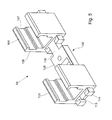
- Fig. 8 to 15 differs from the embodiment described above only by the below described different configuration or shaping of the connection between the support members 108. Incidentally, reference is made to the above description.
- the plate-like support members 108 at their ends on opposite sides of L-shaped or angular recesses 121; 122, which are formed so that at both ends of a support member 108 on respective opposite sides hook-shaped coupling lugs 123; 124 are formed, which are opposite or aligned with each other, wherein the coupling lug 123 of a support member 108 cooperates with the coupling lug 124 of the adjacent support member 108 with play.
- the said play between the carrier elements 108 is created by that the thickness of the hook portion 126 and 127 extending transversely to the longitudinal direction L and formed at the end of the respective coupling projection 123 and 124, respectively, is less than the length measured in the longitudinal direction L of the respective hook portion 126; 127 cooperating leg 128; 129 of the recess 121 and 122, respectively.
- hook-shaped coupling lugs 123; 124 formed so that the free ends of the hook portions 126; 127 on the respective longitudinal web 131; 132 of the respective coupling approach 123 and 124 support, which contributes to the stability of the carrier strand 102.
- the hook portion 127 and the associated leg 128 of the recess 121 is wider than the hook portion 126 and the associated leg 129 of the recess 122, which is achieved even in the case of maximum extension of the support strand 102, in which the individual guide elements 101 maximum are spaced and the gap between adjacent guide elements 101 thus reaches its maximum size, cf. z. B. Fig. 7 , both cooperating coupling parts 123; 124 in both associated guide elements 101 and their hollow profile sections 104; 104 are guided, which also contributes to the stability of the carrier strand.
- the carrier strand 102 is connected at its two ends to a guide element 133 or 134, whose cross-section corresponds to that of the guide elements 101, but which is longer than the guide elements 101.
- the guide elements 133; 134 are connected to the guide rails 09.
- the length variability can be, for example, 3 mm per coupling, ie in the case of the example shown, a total of 15 mm.
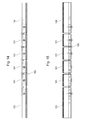
- the further shape-variable guide rail section 57 is in Fig. 16 shown in more detail.
- This guide rail portion 57 is formed variable in length or telescopically extendable and designed substantially as in the above-mentioned
- the guide rail section 57 also has a C-shaped or U-shaped inner cross section and comprises sections 61; 62, which engage relative to each other slidably into one another and always maintain a positive guidance of the roller chain.
- variable guide rail sections 57; 58 are also used elsewhere.
- FIG. 17 An advantageous embodiment of the in the guide rail 09 and the guide rail portions 57; 58 led chain 51 is in Fig. 17 shown.
- the chain 51 has respective rollers mounted on bolts 22, wherein the bolts 22 are connected by means of tabs.
- the chain 51 can not only perform a pivoting movement about the longitudinal axes of the bolt 22, z.
- the holes in the tabs slightly larger than the diameter of the pin 22, so that the chain 51 is transversely to the running direction or in the longitudinal axis direction of the bolt 22 curvable. In the curved state, this results in a maximum radius of curvature R51 of 1,000 mm or, preferably, less than 600 mm, particularly preferably less than 500 mm.
- the bolt 22 in its longitudinal direction with different diameters, in particular crowned execute.
- the superstructure of the folding apparatus preferably has a plurality of ways in which in each case at least one material web 01 can be guided through the superstructure 03 and to the cross-cutting device 24, and then a plurality of rail pieces which run along each of these paths unite in front of the cross-cutting device 24 with the guide rail 09 in a manner not shown.
Applications Claiming Priority (2)
| Application Number | Priority Date | Filing Date | Title |
|---|---|---|---|
| DE102005045041A DE102005045041B3 (de) | 2005-09-21 | 2005-09-21 | Vorrichtung und ein Verfahren zur Verwendung einer Vorrichtung zum Einziehen mindestens einer Materialbahn bzw. mindestens eines Bahnstrangs in einen Falzapparat |
| EP20060778007 EP1926596B1 (fr) | 2005-09-21 | 2006-07-27 | Dispositif d'insertion d'au moins une bande de materiau ou d'au moins un tronçon de bande dans un appareil de pliage |
Related Parent Applications (1)
| Application Number | Title | Priority Date | Filing Date |
|---|---|---|---|
| EP20060778007 Division EP1926596B1 (fr) | 2005-09-21 | 2006-07-27 | Dispositif d'insertion d'au moins une bande de materiau ou d'au moins un tronçon de bande dans un appareil de pliage |
Publications (2)
| Publication Number | Publication Date |
|---|---|
| EP1938977A1 true EP1938977A1 (fr) | 2008-07-02 |
| EP1938977B1 EP1938977B1 (fr) | 2009-06-17 |
Family
ID=37074439
Family Applications (3)
| Application Number | Title | Priority Date | Filing Date |
|---|---|---|---|
| EP20080152825 Not-in-force EP1930163B1 (fr) | 2005-09-21 | 2006-07-27 | Dispositif destiné à introduire au moins une bande de matière ou au moins une rame dans une plieuse |
| EP20060778007 Not-in-force EP1926596B1 (fr) | 2005-09-21 | 2006-07-27 | Dispositif d'insertion d'au moins une bande de materiau ou d'au moins un tronçon de bande dans un appareil de pliage |
| EP20080152822 Not-in-force EP1938977B1 (fr) | 2005-09-21 | 2006-07-27 | Dispositif et procédé destinés à introduire au moins une bande de matière ou au moins une rame dans une plieuse |
Family Applications Before (2)
| Application Number | Title | Priority Date | Filing Date |
|---|---|---|---|
| EP20080152825 Not-in-force EP1930163B1 (fr) | 2005-09-21 | 2006-07-27 | Dispositif destiné à introduire au moins une bande de matière ou au moins une rame dans une plieuse |
| EP20060778007 Not-in-force EP1926596B1 (fr) | 2005-09-21 | 2006-07-27 | Dispositif d'insertion d'au moins une bande de materiau ou d'au moins un tronçon de bande dans un appareil de pliage |
Country Status (6)
| Country | Link |
|---|---|
| US (1) | US7922642B2 (fr) |
| EP (3) | EP1930163B1 (fr) |
| AT (3) | ATE428560T1 (fr) |
| DE (4) | DE102005045041B3 (fr) |
| ES (3) | ES2325640T3 (fr) |
| WO (1) | WO2007033848A1 (fr) |
Families Citing this family (5)
| Publication number | Priority date | Publication date | Assignee | Title |
|---|---|---|---|---|
| DE102007000598B4 (de) | 2007-10-30 | 2011-07-21 | KOENIG & BAUER Aktiengesellschaft, 97080 | Verfahren zum Betreiben einer Vorrichtung zum Führen einer Bahn während eines Einziehvorganges in einer Rotationsdruckmaschine |
| DE102008002764B3 (de) * | 2008-02-01 | 2009-05-07 | Koenig & Bauer Aktiengesellschaft | Vorrichtung und ein Verfahren zum vollautomatischen Einziehen einer Materialbahn aus einem Rollenwechsler in einen Oberbau einer Druckmaschine |
| DE102009061056A1 (de) * | 2009-08-28 | 2011-06-16 | Manroland Ag | Formatvariable Rollendruckmaschine |
| DE102015221919A1 (de) | 2015-11-09 | 2017-05-11 | Koenig & Bauer Ag | Wickelvorrichtung für bahnförmiges Material und Verfahren zum Einziehen zumindest einer Materialbahn in zumindest eine Wickelvorrichtung |
| IT201800004530A1 (it) | 2018-04-16 | 2019-10-16 | Macchina e metodo per la lavorazione di un nastro in materiale per l’industria del tabacco |
Citations (15)
| Publication number | Priority date | Publication date | Assignee | Title |
|---|---|---|---|---|
| US3125335A (en) | 1964-03-17 | Webbing system using preprinted tape | ||
| US4063505A (en) * | 1975-07-21 | 1977-12-20 | Ikegsi Iron Works, Ltd. | Papering apparatus in rotary printing press |
| DE3312038A1 (de) | 1982-06-14 | 1983-12-15 | VEB Kombinat Polygraph "Werner Lamberz" Leipzig, DDR 7050 Leipzig | Vorrichtung zum einziehen von materialbahnen in rotationsdruckmaschinen |
| US4598850A (en) * | 1984-02-15 | 1986-07-08 | M.A.N.-Roland Druckmaschinen Aktiengesellschaft | Web threading arrangement for threading a paper web through a rotary printing machine |
| EP0383515A2 (fr) * | 1989-02-13 | 1990-08-22 | Hamada Printing Press Co. Ltd. | Dispositif préparatoire pour l'alimentation du papier |
| DE4210190A1 (de) | 1992-03-28 | 1993-09-30 | Roland Man Druckmasch | Sicherheitsvorrichtung für laufende Bahnen |
| EP0673764A1 (fr) | 1994-03-22 | 1995-09-27 | MAN Roland Druckmaschinen AG | Dispositif pour introduire des bandes à imprimer |
| EP0553740B1 (fr) | 1992-01-31 | 1996-07-03 | KOENIG & BAUER-ALBERT AKTIENGESELLSCHAFT | Guidage pour enfiler des bandes dans une rotative à imprimer à rouleaux |
| WO1998050234A1 (fr) | 1997-05-02 | 1998-11-12 | Koenig & Bauer Ag | Element de glissiere variable en longueur pour chaine articulee |
| WO2000056646A1 (fr) * | 1999-03-19 | 2000-09-28 | Koenig & Bauer Aktiengesellschaft | Dispositif d'introduction pour bandes de papier |
| DE10038551A1 (de) * | 2000-08-03 | 2002-02-14 | Roland Man Druckmasch | Ermittlung der Voreinstelldaten für das Schnittregister (und das Farbregister) für längswellenlose Druckwerke |
| DE10128821A1 (de) | 2001-06-15 | 2003-01-02 | Koenig & Bauer Ag | Verfahren und Vorrichtung zum Zusammenführen von Materialbahnen |
| WO2004056686A1 (fr) | 2002-12-18 | 2004-07-08 | Koenig & Bauer Aktiengesellschaft | Dispositifs pour traiter et/ou acheminer une bande de matiere, et procede pour les regler |
| WO2005092614A2 (fr) | 2004-03-26 | 2005-10-06 | Koenig & Bauer Aktiengesellschaft | Procedes et dispositifs pour introduire au moins une bande de matiere ou une rame dans une plieuse |
| DE102004022541A1 (de) | 2004-05-05 | 2005-12-01 | Man Roland Druckmaschinen Ag | Vorrichtung zum Einziehen von Materialbahnen in Aggregate von Rotationsdruckmaschinen |
Family Cites Families (4)
| Publication number | Priority date | Publication date | Assignee | Title |
|---|---|---|---|---|
| FR2684042B1 (fr) | 1991-11-26 | 1996-06-07 | Heidelberg Harris Sa | Dispositif d'engagement de bande pour presse a imprimer a bobine. |
| US5211280A (en) * | 1992-03-13 | 1993-05-18 | Storcan Limitee | Adjustable guide rail apparatus for independently adjusting positions of first and second guide rails disposed respectively on opposite sides of the path of a conveyor |
| DE4305955C1 (de) * | 1993-02-26 | 1994-07-21 | Koenig & Bauer Ag | Profilleiste zum Führen einer Rollenkette |
| DE19754106B4 (de) | 1997-12-05 | 2004-04-29 | Man Roland Druckmaschinen Ag | Vorrichtung und Verfahren zum Einziehen einer Bedruckstoffbahn |
-
2005
- 2005-09-21 DE DE102005045041A patent/DE102005045041B3/de not_active Expired - Fee Related
-
2006
- 2006-07-27 EP EP20080152825 patent/EP1930163B1/fr not_active Not-in-force
- 2006-07-27 EP EP20060778007 patent/EP1926596B1/fr not_active Not-in-force
- 2006-07-27 ES ES08152822T patent/ES2325640T3/es active Active
- 2006-07-27 AT AT06778007T patent/ATE428560T1/de not_active IP Right Cessation
- 2006-07-27 WO PCT/EP2006/064710 patent/WO2007033848A1/fr active Application Filing
- 2006-07-27 ES ES06778007T patent/ES2321654T3/es active Active
- 2006-07-27 DE DE200650003480 patent/DE502006003480D1/de active Active
- 2006-07-27 EP EP20080152822 patent/EP1938977B1/fr not_active Not-in-force
- 2006-07-27 AT AT08152825T patent/ATE428561T1/de not_active IP Right Cessation
- 2006-07-27 US US11/992,393 patent/US7922642B2/en not_active Expired - Fee Related
- 2006-07-27 AT AT08152822T patent/ATE433861T1/de not_active IP Right Cessation
- 2006-07-27 DE DE200650004029 patent/DE502006004029D1/de active Active
- 2006-07-27 ES ES08152825T patent/ES2321669T3/es active Active
- 2006-07-27 DE DE200650003484 patent/DE502006003484D1/de active Active
Patent Citations (16)
| Publication number | Priority date | Publication date | Assignee | Title |
|---|---|---|---|---|
| US3125335A (en) | 1964-03-17 | Webbing system using preprinted tape | ||
| US4063505A (en) * | 1975-07-21 | 1977-12-20 | Ikegsi Iron Works, Ltd. | Papering apparatus in rotary printing press |
| DE3312038A1 (de) | 1982-06-14 | 1983-12-15 | VEB Kombinat Polygraph "Werner Lamberz" Leipzig, DDR 7050 Leipzig | Vorrichtung zum einziehen von materialbahnen in rotationsdruckmaschinen |
| US4598850A (en) * | 1984-02-15 | 1986-07-08 | M.A.N.-Roland Druckmaschinen Aktiengesellschaft | Web threading arrangement for threading a paper web through a rotary printing machine |
| EP0383515A2 (fr) * | 1989-02-13 | 1990-08-22 | Hamada Printing Press Co. Ltd. | Dispositif préparatoire pour l'alimentation du papier |
| EP0553740B1 (fr) | 1992-01-31 | 1996-07-03 | KOENIG & BAUER-ALBERT AKTIENGESELLSCHAFT | Guidage pour enfiler des bandes dans une rotative à imprimer à rouleaux |
| DE4210190A1 (de) | 1992-03-28 | 1993-09-30 | Roland Man Druckmasch | Sicherheitsvorrichtung für laufende Bahnen |
| EP0673764A1 (fr) | 1994-03-22 | 1995-09-27 | MAN Roland Druckmaschinen AG | Dispositif pour introduire des bandes à imprimer |
| WO1998050234A1 (fr) | 1997-05-02 | 1998-11-12 | Koenig & Bauer Ag | Element de glissiere variable en longueur pour chaine articulee |
| WO2000056646A1 (fr) * | 1999-03-19 | 2000-09-28 | Koenig & Bauer Aktiengesellschaft | Dispositif d'introduction pour bandes de papier |
| WO2000056652A1 (fr) | 1999-03-19 | 2000-09-28 | Koenig & Bauer Aktiengesellschaft | Procede et dispositif d'introduction pour au moins une bande de papier |
| DE10038551A1 (de) * | 2000-08-03 | 2002-02-14 | Roland Man Druckmasch | Ermittlung der Voreinstelldaten für das Schnittregister (und das Farbregister) für längswellenlose Druckwerke |
| DE10128821A1 (de) | 2001-06-15 | 2003-01-02 | Koenig & Bauer Ag | Verfahren und Vorrichtung zum Zusammenführen von Materialbahnen |
| WO2004056686A1 (fr) | 2002-12-18 | 2004-07-08 | Koenig & Bauer Aktiengesellschaft | Dispositifs pour traiter et/ou acheminer une bande de matiere, et procede pour les regler |
| WO2005092614A2 (fr) | 2004-03-26 | 2005-10-06 | Koenig & Bauer Aktiengesellschaft | Procedes et dispositifs pour introduire au moins une bande de matiere ou une rame dans une plieuse |
| DE102004022541A1 (de) | 2004-05-05 | 2005-12-01 | Man Roland Druckmaschinen Ag | Vorrichtung zum Einziehen von Materialbahnen in Aggregate von Rotationsdruckmaschinen |
Also Published As
| Publication number | Publication date |
|---|---|
| ATE428561T1 (de) | 2009-05-15 |
| DE502006003484D1 (de) | 2009-05-28 |
| EP1930163A3 (fr) | 2008-06-25 |
| EP1926596A1 (fr) | 2008-06-04 |
| EP1930163A2 (fr) | 2008-06-11 |
| ATE433861T1 (de) | 2009-07-15 |
| EP1938977B1 (fr) | 2009-06-17 |
| US7922642B2 (en) | 2011-04-12 |
| WO2007033848A1 (fr) | 2007-03-29 |
| DE502006003480D1 (de) | 2009-05-28 |
| ES2325640T3 (es) | 2009-09-10 |
| US20090108043A1 (en) | 2009-04-30 |
| EP1930163B1 (fr) | 2009-04-15 |
| ES2321654T3 (es) | 2009-06-09 |
| DE502006004029D1 (de) | 2009-07-30 |
| DE102005045041B3 (de) | 2007-02-01 |
| EP1926596B1 (fr) | 2009-04-15 |
| ATE428560T1 (de) | 2009-05-15 |
| ES2321669T3 (es) | 2009-06-09 |
Similar Documents
| Publication | Publication Date | Title |
|---|---|---|
| EP1785379B1 (fr) | Dispositif destiné au traitement et/ou au transport d'une bande dans une machine à pression rotative | |
| EP1930162B1 (fr) | Dispositifs et procédés pour introduire au moins une bande de matière ou une rame dans une plieuse | |
| DE1461915C3 (de) | Vorrichtung zur Herstellung von Quaderpackungen | |
| EP1388516B1 (fr) | Dispositif pour ajuster le répérage d'une découpeuse | |
| EP1938977B1 (fr) | Dispositif et procédé destinés à introduire au moins une bande de matière ou au moins une rame dans une plieuse | |
| EP0658426B1 (fr) | Dispositif de pliage | |
| EP1388515A2 (fr) | Dispositif pour ajuster le répérage d'une découpeuse | |
| DE4439615B4 (de) | Papierbahnzuführung zu einem Falzapparat | |
| EP0957057B1 (fr) | Dispositif de pliage longitudinal pour l'appareil de pliage de machines d'impression rotatives | |
| DE10337248B4 (de) | Bahnspreizverfahren und Bahnspreizvorrichtung | |
| DE19932070A1 (de) | Exemplarführungseinrichtung mit variabler Geometrie | |
| DE202008000890U1 (de) | Bahnspreizeinrichtung für eine Rotationsdruckmaschine und damit ausgerüstete Rotationsdruckmaschine | |
| EP0170179A1 (fr) | Dispositif pour recueillir des produits pliés à partir d'un cylindre à volets de pliage | |
| EP0734988B1 (fr) | Méthode et appareil pour mettre en mouvement des aiguilles de perforation | |
| EP1348571B1 (fr) | Dispositif pour relier des éléments plats empilés | |
| EP1110894B1 (fr) | Méthode et dispositif pour plier des feuilles de matériau | |
| DE102006001949B3 (de) | Vorrichtung zum Einziehen einer Materialbahn | |
| EP1034878A2 (fr) | Dispositif et procédé pour séparer des pièces en forme de barres | |
| DE102006019594B3 (de) | Vorrichtung zum Einziehen einer Bedruckstoffbahn | |
| DE102004064024A1 (de) | Verfahren zum Einziehen von Bahnsträngen in einen Falzapparat |
Legal Events
| Date | Code | Title | Description |
|---|---|---|---|
| PUAI | Public reference made under article 153(3) epc to a published international application that has entered the european phase |
Free format text: ORIGINAL CODE: 0009012 |
|
| AC | Divisional application: reference to earlier application |
Ref document number: 1926596 Country of ref document: EP Kind code of ref document: P |
|
| AK | Designated contracting states |
Kind code of ref document: A1 Designated state(s): AT BE BG CH CY CZ DE DK EE ES FI FR GB GR HU IE IS IT LI LT LU LV MC NL PL PT RO SE SI SK TR |
|
| AX | Request for extension of the european patent |
Extension state: AL BA HR MK RS |
|
| 17P | Request for examination filed |
Effective date: 20080527 |
|
| 17Q | First examination report despatched |
Effective date: 20080901 |
|
| AKX | Designation fees paid |
Designated state(s): AT BE BG CH CY CZ DE DK EE ES FI FR GB GR HU IE IS IT LI LT LU LV MC NL PL PT RO SE SI SK TR |
|
| GRAP | Despatch of communication of intention to grant a patent |
Free format text: ORIGINAL CODE: EPIDOSNIGR1 |
|
| GRAS | Grant fee paid |
Free format text: ORIGINAL CODE: EPIDOSNIGR3 |
|
| GRAA | (expected) grant |
Free format text: ORIGINAL CODE: 0009210 |
|
| AC | Divisional application: reference to earlier application |
Ref document number: 1926596 Country of ref document: EP Kind code of ref document: P |
|
| AK | Designated contracting states |
Kind code of ref document: B1 Designated state(s): AT BE BG CH CY CZ DE DK EE ES FI FR GB GR HU IE IS IT LI LT LU LV MC NL PL PT RO SE SI SK TR |
|
| REG | Reference to a national code |
Ref country code: GB Ref legal event code: FG4D Free format text: NOT ENGLISH |
|
| REG | Reference to a national code |
Ref country code: CH Ref legal event code: EP |
|
| REG | Reference to a national code |
Ref country code: IE Ref legal event code: FG4D Free format text: LANGUAGE OF EP DOCUMENT: GERMAN |
|
| REF | Corresponds to: |
Ref document number: 502006004029 Country of ref document: DE Date of ref document: 20090730 Kind code of ref document: P |
|
| REG | Reference to a national code |
Ref country code: ES Ref legal event code: FG2A Ref document number: 2325640 Country of ref document: ES Kind code of ref document: T3 |
|
| PG25 | Lapsed in a contracting state [announced via postgrant information from national office to epo] |
Ref country code: LT Free format text: LAPSE BECAUSE OF FAILURE TO SUBMIT A TRANSLATION OF THE DESCRIPTION OR TO PAY THE FEE WITHIN THE PRESCRIBED TIME-LIMIT Effective date: 20090617 Ref country code: FI Free format text: LAPSE BECAUSE OF FAILURE TO SUBMIT A TRANSLATION OF THE DESCRIPTION OR TO PAY THE FEE WITHIN THE PRESCRIBED TIME-LIMIT Effective date: 20090617 |
|
| PG25 | Lapsed in a contracting state [announced via postgrant information from national office to epo] |
Ref country code: LV Free format text: LAPSE BECAUSE OF FAILURE TO SUBMIT A TRANSLATION OF THE DESCRIPTION OR TO PAY THE FEE WITHIN THE PRESCRIBED TIME-LIMIT Effective date: 20090617 Ref country code: PL Free format text: LAPSE BECAUSE OF FAILURE TO SUBMIT A TRANSLATION OF THE DESCRIPTION OR TO PAY THE FEE WITHIN THE PRESCRIBED TIME-LIMIT Effective date: 20090617 Ref country code: SE Free format text: LAPSE BECAUSE OF FAILURE TO SUBMIT A TRANSLATION OF THE DESCRIPTION OR TO PAY THE FEE WITHIN THE PRESCRIBED TIME-LIMIT Effective date: 20090917 Ref country code: SI Free format text: LAPSE BECAUSE OF FAILURE TO SUBMIT A TRANSLATION OF THE DESCRIPTION OR TO PAY THE FEE WITHIN THE PRESCRIBED TIME-LIMIT Effective date: 20090617 |
|
| NLV1 | Nl: lapsed or annulled due to failure to fulfill the requirements of art. 29p and 29m of the patents act | ||
| REG | Reference to a national code |
Ref country code: IE Ref legal event code: FD4D |
|
| PG25 | Lapsed in a contracting state [announced via postgrant information from national office to epo] |
Ref country code: IE Free format text: LAPSE BECAUSE OF FAILURE TO SUBMIT A TRANSLATION OF THE DESCRIPTION OR TO PAY THE FEE WITHIN THE PRESCRIBED TIME-LIMIT Effective date: 20090617 Ref country code: IS Free format text: LAPSE BECAUSE OF FAILURE TO SUBMIT A TRANSLATION OF THE DESCRIPTION OR TO PAY THE FEE WITHIN THE PRESCRIBED TIME-LIMIT Effective date: 20091017 Ref country code: EE Free format text: LAPSE BECAUSE OF FAILURE TO SUBMIT A TRANSLATION OF THE DESCRIPTION OR TO PAY THE FEE WITHIN THE PRESCRIBED TIME-LIMIT Effective date: 20090617 Ref country code: CZ Free format text: LAPSE BECAUSE OF FAILURE TO SUBMIT A TRANSLATION OF THE DESCRIPTION OR TO PAY THE FEE WITHIN THE PRESCRIBED TIME-LIMIT Effective date: 20090617 Ref country code: RO Free format text: LAPSE BECAUSE OF FAILURE TO SUBMIT A TRANSLATION OF THE DESCRIPTION OR TO PAY THE FEE WITHIN THE PRESCRIBED TIME-LIMIT Effective date: 20090617 |
|
| BERE | Be: lapsed |
Owner name: KOENIG & BAUER A.G. Effective date: 20090731 |
|
| PG25 | Lapsed in a contracting state [announced via postgrant information from national office to epo] |
Ref country code: NL Free format text: LAPSE BECAUSE OF FAILURE TO SUBMIT A TRANSLATION OF THE DESCRIPTION OR TO PAY THE FEE WITHIN THE PRESCRIBED TIME-LIMIT Effective date: 20090617 Ref country code: SK Free format text: LAPSE BECAUSE OF FAILURE TO SUBMIT A TRANSLATION OF THE DESCRIPTION OR TO PAY THE FEE WITHIN THE PRESCRIBED TIME-LIMIT Effective date: 20090617 Ref country code: MC Free format text: LAPSE BECAUSE OF NON-PAYMENT OF DUE FEES Effective date: 20090731 |
|
| PG25 | Lapsed in a contracting state [announced via postgrant information from national office to epo] |
Ref country code: PT Free format text: LAPSE BECAUSE OF FAILURE TO SUBMIT A TRANSLATION OF THE DESCRIPTION OR TO PAY THE FEE WITHIN THE PRESCRIBED TIME-LIMIT Effective date: 20091017 Ref country code: BG Free format text: LAPSE BECAUSE OF FAILURE TO SUBMIT A TRANSLATION OF THE DESCRIPTION OR TO PAY THE FEE WITHIN THE PRESCRIBED TIME-LIMIT Effective date: 20090917 |
|
| PLBE | No opposition filed within time limit |
Free format text: ORIGINAL CODE: 0009261 |
|
| STAA | Information on the status of an ep patent application or granted ep patent |
Free format text: STATUS: NO OPPOSITION FILED WITHIN TIME LIMIT |
|
| PG25 | Lapsed in a contracting state [announced via postgrant information from national office to epo] |
Ref country code: DK Free format text: LAPSE BECAUSE OF FAILURE TO SUBMIT A TRANSLATION OF THE DESCRIPTION OR TO PAY THE FEE WITHIN THE PRESCRIBED TIME-LIMIT Effective date: 20090617 |
|
| 26N | No opposition filed |
Effective date: 20100318 |
|
| PG25 | Lapsed in a contracting state [announced via postgrant information from national office to epo] |
Ref country code: BE Free format text: LAPSE BECAUSE OF NON-PAYMENT OF DUE FEES Effective date: 20090731 |
|
| PG25 | Lapsed in a contracting state [announced via postgrant information from national office to epo] |
Ref country code: GR Free format text: LAPSE BECAUSE OF FAILURE TO SUBMIT A TRANSLATION OF THE DESCRIPTION OR TO PAY THE FEE WITHIN THE PRESCRIBED TIME-LIMIT Effective date: 20090918 |
|
| PG25 | Lapsed in a contracting state [announced via postgrant information from national office to epo] |
Ref country code: AT Free format text: LAPSE BECAUSE OF NON-PAYMENT OF DUE FEES Effective date: 20090727 |
|
| PG25 | Lapsed in a contracting state [announced via postgrant information from national office to epo] |
Ref country code: LU Free format text: LAPSE BECAUSE OF NON-PAYMENT OF DUE FEES Effective date: 20090727 |
|
| PG25 | Lapsed in a contracting state [announced via postgrant information from national office to epo] |
Ref country code: HU Free format text: LAPSE BECAUSE OF FAILURE TO SUBMIT A TRANSLATION OF THE DESCRIPTION OR TO PAY THE FEE WITHIN THE PRESCRIBED TIME-LIMIT Effective date: 20091218 |
|
| PG25 | Lapsed in a contracting state [announced via postgrant information from national office to epo] |
Ref country code: TR Free format text: LAPSE BECAUSE OF FAILURE TO SUBMIT A TRANSLATION OF THE DESCRIPTION OR TO PAY THE FEE WITHIN THE PRESCRIBED TIME-LIMIT Effective date: 20090617 |
|
| PG25 | Lapsed in a contracting state [announced via postgrant information from national office to epo] |
Ref country code: CY Free format text: LAPSE BECAUSE OF FAILURE TO SUBMIT A TRANSLATION OF THE DESCRIPTION OR TO PAY THE FEE WITHIN THE PRESCRIBED TIME-LIMIT Effective date: 20090617 |
|
| PGFP | Annual fee paid to national office [announced via postgrant information from national office to epo] |
Ref country code: CH Payment date: 20110714 Year of fee payment: 6 |
|
| PGFP | Annual fee paid to national office [announced via postgrant information from national office to epo] |
Ref country code: GB Payment date: 20120726 Year of fee payment: 7 |
|
| PGFP | Annual fee paid to national office [announced via postgrant information from national office to epo] |
Ref country code: IT Payment date: 20120725 Year of fee payment: 7 Ref country code: FR Payment date: 20120808 Year of fee payment: 7 Ref country code: ES Payment date: 20120718 Year of fee payment: 7 |
|
| REG | Reference to a national code |
Ref country code: CH Ref legal event code: PL |
|
| GBPC | Gb: european patent ceased through non-payment of renewal fee |
Effective date: 20130727 |
|
| REG | Reference to a national code |
Ref country code: FR Ref legal event code: ST Effective date: 20140331 |
|
| PG25 | Lapsed in a contracting state [announced via postgrant information from national office to epo] |
Ref country code: GB Free format text: LAPSE BECAUSE OF NON-PAYMENT OF DUE FEES Effective date: 20130727 Ref country code: LI Free format text: LAPSE BECAUSE OF NON-PAYMENT OF DUE FEES Effective date: 20130731 Ref country code: CH Free format text: LAPSE BECAUSE OF NON-PAYMENT OF DUE FEES Effective date: 20130731 |
|
| PG25 | Lapsed in a contracting state [announced via postgrant information from national office to epo] |
Ref country code: IT Free format text: LAPSE BECAUSE OF NON-PAYMENT OF DUE FEES Effective date: 20130727 Ref country code: FR Free format text: LAPSE BECAUSE OF NON-PAYMENT OF DUE FEES Effective date: 20130731 |
|
| REG | Reference to a national code |
Ref country code: ES Ref legal event code: FD2A Effective date: 20140909 |
|
| PG25 | Lapsed in a contracting state [announced via postgrant information from national office to epo] |
Ref country code: ES Free format text: LAPSE BECAUSE OF NON-PAYMENT OF DUE FEES Effective date: 20130728 |
|
| REG | Reference to a national code |
Ref country code: DE Ref legal event code: R081 Ref document number: 502006004029 Country of ref document: DE Owner name: KOENIG & BAUER AG, DE Free format text: FORMER OWNER: KOENIG & BAUER AKTIENGESELLSCHAFT, 97080 WUERZBURG, DE |
|
| PGFP | Annual fee paid to national office [announced via postgrant information from national office to epo] |
Ref country code: DE Payment date: 20150918 Year of fee payment: 10 |
|
| REG | Reference to a national code |
Ref country code: DE Ref legal event code: R119 Ref document number: 502006004029 Country of ref document: DE |
|
| PG25 | Lapsed in a contracting state [announced via postgrant information from national office to epo] |
Ref country code: DE Free format text: LAPSE BECAUSE OF NON-PAYMENT OF DUE FEES Effective date: 20170201 |