EP0553740B1 - Guidage pour enfiler des bandes dans une rotative à imprimer à rouleaux - Google Patents
Guidage pour enfiler des bandes dans une rotative à imprimer à rouleaux Download PDFInfo
- Publication number
- EP0553740B1 EP0553740B1 EP93101046A EP93101046A EP0553740B1 EP 0553740 B1 EP0553740 B1 EP 0553740B1 EP 93101046 A EP93101046 A EP 93101046A EP 93101046 A EP93101046 A EP 93101046A EP 0553740 B1 EP0553740 B1 EP 0553740B1
- Authority
- EP
- European Patent Office
- Prior art keywords
- guide
- profile
- fixed
- movable
- roller
- Prior art date
- Legal status (The legal status is an assumption and is not a legal conclusion. Google has not performed a legal analysis and makes no representation as to the accuracy of the status listed.)
- Expired - Lifetime
Links
- 239000000463 material Substances 0.000 claims description 15
- 230000006835 compression Effects 0.000 description 5
- 238000007906 compression Methods 0.000 description 5
- 238000005553 drilling Methods 0.000 description 3
- 238000010516 chain-walking reaction Methods 0.000 description 2
- 241000219098 Parthenocissus Species 0.000 description 1
- XAGFODPZIPBFFR-UHFFFAOYSA-N aluminium Chemical compound [Al] XAGFODPZIPBFFR-UHFFFAOYSA-N 0.000 description 1
- 229910052782 aluminium Inorganic materials 0.000 description 1
- 230000015572 biosynthetic process Effects 0.000 description 1
- 238000010586 diagram Methods 0.000 description 1
- 239000013013 elastic material Substances 0.000 description 1
- 238000005516 engineering process Methods 0.000 description 1
- 238000000034 method Methods 0.000 description 1
- 239000011343 solid material Substances 0.000 description 1
Images


Classifications
-
- B—PERFORMING OPERATIONS; TRANSPORTING
- B41—PRINTING; LINING MACHINES; TYPEWRITERS; STAMPS
- B41F—PRINTING MACHINES OR PRESSES
- B41F13/00—Common details of rotary presses or machines
- B41F13/02—Conveying or guiding webs through presses or machines
- B41F13/03—Threading webs into printing machines
Definitions
- the invention relates to a guide for pulling a web of material into a web-fed rotary printing press according to the preamble of patent claim 1.
- a disadvantage of the adjustment device mentioned is the high outlay in terms of gear technology and the fact that the register roller has to be fine-tuned again and again with recurring courses of the material webs.
- the present invention has for its object to provide a guide that can be adapted to the variable spacing of the guide rollers.
- the advantages of the solution according to the invention are, in particular, that the material web is always guided directly around the adjustable guide roller when it is drawn in, regardless of its current position.
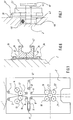
- FIG. 1 is a schematic representation of a nine-cylinder web-fed rotary printing press with a material web 1 as a full line or dash-dotted material webs, which can take a course that these with the guide rollers 3 arranged in the machine frame wall 2; 4; 6; 7; 8th; 9 or adjustable guide rollers 11; 12, the adjustable guide rollers 11; 12 in maximum adjustment position 11 '; 12 ', the plate cylinders 13; 14, the blanket cylinders 16; 17; 18; 19; 21; 22 and the impression cylinder 23 come into direct or indirect contact and can leave the printing press shown via the guide rollers 3 or 4.
- FIG. 2 shows a device according to the invention, which is arranged in the region of the adjustable guide roller 11 on a machine frame wall 2 according to FIG. 1.
- the chain guide consists of a frame-fixed guide, generally designated 24, and a movable guide, generally designated 26.
- the frame-fixed guide 24 comprises a cross-sectionally C-shaped profile 27 with a wedge piece 28. Parallel to the parts 27; 28, but at a distance which corresponds to a maximum of the width of a C-shaped profile 27, run on both sides of the parts 27; 28 boundary strips 29; 31, each of which on one longitudinal side by means of a receptacle 30 a half rail 41; 42 can take up or guide a chain rail.
- the guide 24 fixed to the frame further comprises a holder 32; 33, which is analogous to the boundary strips 29; 31 on one long side a half rail 41; 42 can record or guide, also with a receptacle 34, which has a bend in the area of the tip of the wedge piece 28, just enough that in each case a half-rail 41; 42 can be included.
- the bracket 32; 33 can be guided by bolts 35 fixed to the frame.
- the parts of the fixed guide 24 are fastened by means of threaded screws 36 on the machine frame wall 2 shown in FIGS. 1 and 6.
- the movable guide 26 consists of a base plate 37 on which a holder 38; 39 is attached to accommodate the chain track.
- the chain running rail consists of two half rails 41 in the area of the guide 24 fixed to the frame; 42, which can be made, for example, from a rubber profile and in the region of the movable guide 26, for example from plastic or aluminum with a C-shaped profile 27.
- a cross section through the chain track is shown in Fig. 6.
- the movable guide 26 consists of an arc-shaped C-profile 27, which is guided on the base plate 37 around the adjustable guide roller 11 with axis 43.
- the roller chain 44 which is not shown in its entire length and is used to pull in the material web, is located in the chain running track made of C-profile 27.
- FIG. 7 shows the view A according to FIG. 3, in which in addition to the adjustable guide roller 11 in position 11 'and the arch made of C-profile 27, it can be seen in particular that the axis 43 is held in a sliding block 46.
- Special bearing elements for the axis 43 have not been shown for the sake of simplicity.
- the sliding block 46 is guided in a groove 47 of the machine frame wall 2 and carries the entire movable guide 26 via the axis 43. Instead of a groove in the machine frame wall, a profile strip can also be attached to the machine frame wall.
- the sliding block 46 can be moved by means of a threaded spindle 48 in the direction of arrow B according to FIG. 2 or arrow direction C according to FIG. 3.
- the threaded spindle 48 is actuated by a servomotor, not shown.
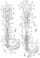
- Fig. 3 the stroke length d is shown by the amount the adjustable guide roller 11 has moved into position 11 ', the guide roller being always surrounded by the chain track 27, regardless of its current position.
- FIG. 5 a second embodiment variant of the solution according to the invention is shown, the device according to FIG. 5 being movable in direction C by the amount d in order to assume the position according to FIG. 4.
- the guide 49 fixed to the frame comprises two half rails 41; 42 made of elastic material, which are fastened on the machine frame wall 2 by means of threaded screws 36.
- the remaining components stand with the movable guide 51 in connection, including a sliding block 46 shown in FIG. 6 in the groove 47.
- the movable guide comprises in particular a base plate 52 with an arc-shaped C-profile 27 made of solid material with a wedge piece 28 which is fastened on the base plate 52 with threaded screws 36.
- Parallel to the rectilinear profile 27 on the base plate 52 are limiting strips 29; 31 arranged, with one of its long side, the half rails 41; 42 record.
- the base plate 52 has, on the side pointing in the direction of the guide 49 fixed to the frame, an extension 53 which has a holder 32; 33 wears.
- This bracket 32; 33 has a receptacle 34, which has a bend in the region of the tip of the wedge piece 28, just enough that between the bend and the tip of the wedge piece 28 a half rail 41; 42 can be included.
- FIG. 8 and 9 show a third embodiment variant of the device according to the invention, which according to FIG. 8 can be moved in the direction of arrow B in order to reach the position 11 'of the adjustable guide roller 11 according to FIG. 9.
- the total stroke length d is composed of the stroke length d 1 to d 8 , which can be seen from FIG. 9. More or fewer guide links can also be used.
- the device consists of a guide 53 fixed to the frame, which is fastened by means of threaded screws 36 to the machine frame wall 2 shown in FIG. 1 and consists of a C-profile 27 which has guide rods 82; 83 may contain.
- guide rods 82; 83 other guides, for example T-slot guides or the like, can also be used.
- a movable guide 54 consists overall of a base plate 56 on which a semicircular C-profile 27 is fastened, which is guided around the guide roller 11.
- the base plate 56 is held by means of a threaded spindle 48 via the axis 43 according to FIG. 7 in a sliding block 46 which is guided in a groove 47 in the machine frame wall 2.
- the movable guide 54 consists of a number of guide members which can be pulled out against one another and which are designated overall by 57 and are shown in section in FIG. 14 and in perspective in FIG. 13 .
- FIG. 12 A view E according to FIG. 9 is shown in FIG. 12.
- the guide member 57 consists of a base body 58 with a substantially C-shaped cross section for the purpose of accommodating the roller chain 44.
- the base body 58 has two lateral extensions or tabs 59 running in the axial direction; 61, at the end of each a bolt 62; 63 is arranged.
- the base body 58 there are two recesses 64; 66 introduced so that on the of the tabs 59; 61 facing away from the base body 58 four free legs 67; 68; 69; 71 result.
- the adjacent legs 67; 68 have slots 72; 73 on.
- the opposite two legs 69; 71 are with an axial through bore 74; 76 provided, which penetrates the entire base body 58.
- the bore 74; 76 has a depression 77 at each end; 78 on for receiving a compression spring 79; 81.
- the adjacent guide members 57 are connected in that the tabs 59; 61 of one body in the recesses 64; 66 engage the adjacent body and the on the tabs 59; 61 located bolts 62; 63 in the slots 72; 73 are performed.
- bolts and slots differently shaped stops and limits can be used.
- the individual guide members 57 connect with each other. Between the individual guide members 57 are on the guide rods 82; 83 the compression springs 79; 81 applied by the depressions 77; 78 according to the position of the movable guide 54 according to FIG. 8.
- Fig. 12 the drivers 84 of the roller chain 44 are shown, to which the web of material to be drawn is attached.
- the length of the slots 72; 73 corresponds approximately to the partial stroke lengths d 1 to d n .
- FIG. 10 and 11 show a fourth embodiment variant of the device according to the invention, which according to FIG. 10 can be moved in the direction of arrow B in order to reach the position 11 'of the adjustable guide roller 11 according to FIG. 11.
- the total stroke length d is composed of the stroke lengths d 1 to d 8 .
- the device consists of a guide 86 fixed to the frame, which is fastened by means of threaded screws 36 to the machine frame wall 2 shown in FIG. 1 and consists of a C-profile 27, the guide rods 82; 83 records.
- a movable guide 87 consists overall of a base plate 56 on which a semicircular C-profile 27 is fastened, which is guided around the guide roller 11.
- the base plate 56 is held by means of a threaded spindle 48 via the axis 43 according to FIG. 7 in a sliding block 46 which is in a groove 47 in the Machine frame wall 2 is guided.
- the movable guide 87 consists of a number of guide members which can be pulled out from one another, which are designated overall by 88 and shown in FIG. 15 as an enlarged illustration and in FIG. 16 in a perspective illustration are.
- the guide member 88 consists of a base body 89 with a substantially C-shaped cross section (FIG. 16) for the purpose of accommodating the roller chain 44.
- the base body 89 has two lateral extensions or extending in the axial direction Tabs 59; 61, at the end of each a bolt 62; 63 is arranged.
- the base body 89 there are two recesses 64; 66 introduced so that on the of the tabs 59; 61 facing away from the base body 89 four free legs 67; 68; 69; 71 result.
- the adjacent legs 67; 68 have slots 72; 73 on.
- the opposite two legs 69; 71 are with an axial through bore 74; 76 provided, which penetrates the entire base body 89.
- the bore 74; 76 has a depression 77 at each end; 78 on for receiving a compression spring 79; 81 analogous to FIG. 12.
- the guide member 88 is half-sided when viewed in the axial direction offset, ie the components 67; 59 are, viewed on the center line 91, opposite the components 68; 61 offset by the amount d x .
- the method of operation is analogous to the description of the third variant. This has the advantage over the design of the guide link 57 according to FIG. 13 that the roller chain 44 is permanently guided on three sides from four sides of the C-shaped profile 27, which results in better guidance of the roller chain.
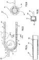
- FIGS. 17 and 18 a fifth embodiment variant of the device according to the invention is shown, which according to FIG. 17 can be moved in the direction of arrow B in order to reach the position 11 ′ of the adjustable guide roller 11 according to FIG. 18.
- a stroke length f is achieved which is greater than the previous stroke length d.
- the guide roller 11 according to FIG. 17 is in a position above the guide roller 8. This arrangement can be used in particular in registering in the substructure if two different printing towers have to be approached, for example at 4/1. or 4/4 printing and if the connection is made through the machine base.
- the device consists of a guide fixed to the frame, which is designated overall by 92 and is shown in the section XIX - XIX according to FIG. 18 in FIG. 19.
- This guide 92 fixed to the frame consists of a holder 93; 94, which by means of threaded screws 36 on the in Fig. 1st shown machine frame wall 2 is attached.
- To the bracket 93; 94 is followed by a semicircular C-profile 25, which is also fastened to the machine frame wall 2 by means of threaded screws and is placed around the fixed guide roller 8 according to FIG. 1.
- the movable guide is designated overall by 96 and consists overall of a base plate 97 on which a semicircular C-profile 27 is fastened, which is guided around the guide roller 11.
- the base plate 97 is held by means of a threaded spindle 48 via the axis 43 according to FIG. 7 in a sliding block 46 which is guided in a groove 47 in the machine frame wall 2.
- the semicircular C-profile 27 is followed by a guide rail 97 which, in the position shown in FIG. 18, receives the roller chain 44 together with the holder 94.
- the roller chain 44 is only indicated by a few chain links.
- FIGS. 20 and 21 a sixth embodiment variant of the device according to the invention is shown, which according to FIG. 20 can be moved in the direction of arrow B in order to reach the position 11 ′ of the adjustable guide roller 11 according to FIG. 21.
- a stroke length f is also achieved which is greater than the previous stroke length d of the first four variants.
- the guide roller 11 according to FIG. 17 is in a position above the guide roller 8. This arrangement can be used in particular in the cases as set out in variant five.
- the device consists of a guide which is fixed to the frame and which is designated overall by 98 and is shown in the section XIX-XIX according to FIG. 21 in FIG. 19.
- This guide 98 fixed to the frame consists of a holder 93; 94, which is fastened by means of threaded screws 36 on the machine frame wall 2 shown in FIG. 1.
- To the bracket 93; 94 is followed by a semicircular C-profile 25, which is also fastened to the machine frame wall 2 by means of threaded screws and is placed around the fixed guide roller 8 according to FIG. 1.
- a wedge-shaped derivative 99 is placed on the outer side of the semicircular C-profile 27, which extends around the fixed guide roller 8, with a guide for receiving articulated guide members 100.
- the movable guide is generally designated 101 and consists overall of a base plate 97 on which a semicircular C-profile 27 is fastened, which is guided around the guide roller 11.
- the base plate 97 is held by means of a threaded spindle 48 via the axis 43 according to FIG. 7 in a sliding block 46 which is guided in a groove 47 in the machine frame wall 2.
- a guide rail 97 'adjoins the semicircular C-profile 27 and, in the position shown in FIG. 21, receives the roller chain 44 together with the holder 94.
- the roller chain 44 is only indicated by a few chain links.
- the guide 97 ' consists of the guide links 100 which are connected to one another in an articulated manner and receive the roller chain 44.
- the guide members 102 are shown in perspective in FIG. 22.
- the guide links 100 have a profile 97, 97 'according to FIG. 19 and, together with the holder 94, form the C-shaped receptacle for the roller chain 44.
- the guide link 100 has a tab 102 with a bore 103, which extends into a rear recess 104 with a bore 105 of a further guide member 100, not shown.
- the guide members 100 are connected to one another by means of pins 106.
- a seventh embodiment of the device according to the invention is shown, which according to FIG. 23 can be moved in the direction of arrow C in order to reach position 11 of the adjustable guide roller according to FIG. 1.
- a stroke length d is achieved.
- the device consists of a guide which is fixed to the frame and which is designated as a whole by 107.
- This frame-fixed guide 102 consists of a C-shaped profile 108 which is fastened by means of threaded screws 36 on the machine frame wall 2 shown in FIG. 1.
- the movable guide is generally designated 109 and consists of a base plate 111, on which a semicircular C-profile 112 is attached, which around the Guide roller 11 is guided around.
- the base plate 111 is held by means of a threaded spindle 48 via the axis 43 according to FIG. 7 in a sliding block 46 which is guided in a groove 47 in the machine frame wall 2.
- the C-shaped profile 112 can be pushed telescopically into the C-profile 108 and, according to FIG. 24, has wedge-shaped outlets 113 at its end in order to be able to run the roller chain 44 smoothly in both running directions.
- the roller chain 44 is only indicated by a chain link with drivers 84.
- the stroke length is marked with d.
- a further guide which has a profile 114, which is essentially C-shaped, accommodates a further profile 116 and can be shifted into one another analogously to FIG. 23.
- the profiles 114; 116 accommodate a traction means 117, which can have a round, oval, square or rectangular cross section or variants thereof and has drivers 84 on the side for fastening the material web to be drawn in.
- the traction means 117 can be made of plastic, for example, and driven by friction wheel gears, not shown.
Landscapes
- Engineering & Computer Science (AREA)
- Mechanical Engineering (AREA)
- Folding Of Thin Sheet-Like Materials, Special Discharging Devices, And Others (AREA)
- Rotary Presses (AREA)
- Registering, Tensioning, Guiding Webs, And Rollers Therefor (AREA)
- Feeding Of Articles By Means Other Than Belts Or Rollers (AREA)
Claims (15)
- Moyen de guidage pour enfiler une bande de matériau dans une presse rotative à bobines à l'aide d'un moyen de traction (44 ; 117) passant dans un moyen de guidage (24 ; 26) et en contournant des rouleaux conducteurs (11) mobiles dans la direction de déplacement de la bande de matériau à imprimer ou d'autres obstacles, caractérisé en ce qu'une partie du moyen de guidage (24 ; 49 ; 53 ; 86 ; 92 ; 98 ; 107) est fixe, et en ce qu'au moins une autre partie (26 ; 51 ; 54 ; 87 ; 96 ; 101 ; 109) du moyen de guidage (24 ; 26 ; 49 ; 51 ; 53 ; 54 ; 86 ; 87 ; 92 ; 96 ; 98 ; 101 ; 107 ; 109) peut coulisser de manière rectiligne en formant une liaison permanente par complémentarité de formes avec la partie fixe (24 ; 49 ; 53 ; 86 ; 92 ; 98 ; 107), sans que le moyen de guidage (24 ; 26 ; 49 ; 51 ; 53 ; 54 ; 86 ; 87 ; 92 ; 96 ; 98 ; 101 ; 107 ; 109) ne soit interrompu.
- Moyen de guidage selon la revendication 1, caractérisé en ce que le rouleau conducteur mobile (11 ; 11' ; 12 ; 12') est directement entouré par un moyen de guidage ininterrompu (24 ; 26 ; 49 ; 51 ; 53 ; 54 ; 86 ; 87 ; 92 ; 96 ; 98 ; 101 ; 107 ; 109) du moyen de traction (44 ; 117), et la longueur du moyen de guidage (24 ; 26 ; 49 ; 51 ; 53 ; 54 ; 86 ; 87 ; 92 ; 96 ; 98 ; 101 ; 107 ; 109) est variable en fonction de la position du rouleau conducteur (11 ; 11' ; 12, 12'), en ce que le moyen de guidage (24 ; 26 ; 49 ; 51 ; 53 ; 54 ; 86 ; 87 ; 92 ; 96 ; 98 ; 101 ; 107 ; 109) est formé d'un moyen de guidage (24 ; 49 ; 53 ; 86 ; 92 ; 98 ; 107) solidaire du bâti et d'un moyen de guidage (26 ; 51 ; 54 ; 87 ; 96 ; 101 ; 109) à longueur télescopiquement variable selon une course (d ; f).
- Moyen de guidage selon les revendications 1 et 2, caractérisé en ce que le moyen de traction est conçu sous la forme d'une chaîne à rouleaux (44).
- Moyen de guidage selon les revendications 1 à 3, caractérisé en ce qu'un profil en C en matériau élastique (27) réalisé en deux parties séparables est disposé dans le moyen de guidage (24 ; 26 ; 49 : 51 ; 53 ; 54 ; 86 ; 87 ; 92 ; 96 ; 98 ; 101 ; 107 ; 109) pour recevoir une chaîne à rouleaux (44).
- Moyen de guidage selon les revendications 1 à 4, caractérisé en ce que le moyen de guidage (24) solidaire du bâti comporte une pièce en coin (28), contre laquelle peut être déplacé le moyen de guidage mobile (26).
- Moyen de guidage selon les revendications 1 à 4, caractérisé en ce que seul le moyen de guidage mobile (51) comporte une pièce en coin (28).
- Moyen de guidage selon les revendications 1 à 3, caractérisé en ce que le moyen de guidage (53 ; 86) solidaire du bâti est réalisé dans un profil en C (27), et en ce que le moyen de guidage mobile (54 ; 87) est constitué de plusieurs maillons de guidage (57 ; 88) pouvant être emmanchés les uns dans les autres sur une distance totale (d).
- Moyen de guidage selon les revendications 1 à 3, caractérisé en ce que le moyen de guidage (92) solidaire du bâti est constitué par un support (93 ; 94), et en ce que le moyen de guidage mobile (96) comporte une glissière de guidage (97) pouvant coulisser sur une distance (f).
- Moyen de guidage selon les revendications 1 à 3, caractérisé en ce que le moyen de guidage (98) solidaire du bâti est constitué d'un support (93 ; 94) sur lequel est disposé un profil en C semi-circulaire (27) et est rapporté un moyen de déviation (99) en forme de coin, et en ce que le moyen de guidage mobile (101) comporte une glissière de guidage (97') qui peut coulisser sur une distance totale (f) et qui possède des maillons de guidage (100) pouvant coulisser individuellement.
- Moyen de guidage selon les revendications 1 à 3, caractérisé en ce que le moyen de guidage (107) solidaire du bâti est constitué par un profit en C (108), et en ce que le moyen de guidage mobile (109) est constitué par un profil en C (112) qui peut être emmanché télescopiquement dans le profil en C (108).
- Moyen de guidage selon les revendications 1 à 10, caractérisé en ce que le moyen de guidage fixe (24 ; 49 ; 53 ; 86 ; 92 ; 98 ; 107) est fixé à la paroi (2) du bâti de la machine au moyen de vis filetées (36).
- Moyen de guidage selon les revendications 1 à 11, caractérisé en ce que le moyen de guidage mobile (26 ; 51 ; 54 ; 87 ; 96 ; 101 ; 109) est fixé sur un socle (37 ; 52 ; 56 ; 111) qui reçoit également l'axe (43) du rouleau conducteur mobile (11 ; 12), et en ce que l'axe (43) est monté dans un coulisseau (46) qui peut coulisser dans une rainure (47) de la paroi (2) du bâti de la machine au moyen d'une tige filetée (48).
- Moyen de guidage selon les revendications 1 et 2 ainsi que 10 à 12, caractérisé en ce que le moyen de traction est conçu sous la forme d'un câble (117) à section transversale ronde.
- Moyen de guidage selon la revendication 13, caractérisé en ce que le moyen de guidage (107) solidaire du bâti est constitué par un profit en C (116) qui peut être emmanché télescopiquement dans le profit en C (114).
- Moyen de guidage selon les revendications 1 et 2 ainsi que 10 à 12, caractérisé en ce que le moyen de traction est conçu sous la forme d'un câble (117) à section carrée, rectangulaire, ovale ou triangulaire.
Applications Claiming Priority (2)
| Application Number | Priority Date | Filing Date | Title |
|---|---|---|---|
| DE4202713 | 1992-01-31 | ||
| DE4202713A DE4202713C2 (de) | 1992-01-31 | 1992-01-31 | Fuehrung zum einziehen einer materialbahn in eine rollenrotationsdruckmaschine |
Publications (2)
| Publication Number | Publication Date |
|---|---|
| EP0553740A1 EP0553740A1 (fr) | 1993-08-04 |
| EP0553740B1 true EP0553740B1 (fr) | 1996-07-03 |
Family
ID=6450651
Family Applications (1)
| Application Number | Title | Priority Date | Filing Date |
|---|---|---|---|
| EP93101046A Expired - Lifetime EP0553740B1 (fr) | 1992-01-31 | 1993-01-23 | Guidage pour enfiler des bandes dans une rotative à imprimer à rouleaux |
Country Status (4)
| Country | Link |
|---|---|
| US (1) | US5263414A (fr) |
| EP (1) | EP0553740B1 (fr) |
| JP (1) | JP2574110B2 (fr) |
| DE (2) | DE4202713C2 (fr) |
Cited By (5)
| Publication number | Priority date | Publication date | Assignee | Title |
|---|---|---|---|---|
| DE102004033036A1 (de) * | 2004-03-26 | 2005-10-20 | Koenig & Bauer Ag | Falzapparat mit einem Oberbau und Verfahren zum Einziehen von Bahnsträngen bzw. einer Materialbahn in einen Falzapparat |
| DE102005045041B3 (de) * | 2005-09-21 | 2007-02-01 | Koenig & Bauer Ag | Vorrichtung und ein Verfahren zur Verwendung einer Vorrichtung zum Einziehen mindestens einer Materialbahn bzw. mindestens eines Bahnstrangs in einen Falzapparat |
| DE102005045038B3 (de) * | 2005-09-21 | 2007-04-12 | Koenig & Bauer Ag | Transportvorrichtung zum Einzug einer Materialbahn |
| DE102008002764B3 (de) * | 2008-02-01 | 2009-05-07 | Koenig & Bauer Aktiengesellschaft | Vorrichtung und ein Verfahren zum vollautomatischen Einziehen einer Materialbahn aus einem Rollenwechsler in einen Oberbau einer Druckmaschine |
| CN100522610C (zh) * | 2004-03-26 | 2009-08-05 | 柯尼格及包尔公开股份有限公司 | 将材料带或带束牵引到折页机内的装置和方法 |
Families Citing this family (26)
| Publication number | Priority date | Publication date | Assignee | Title |
|---|---|---|---|---|
| DE4318299A1 (de) * | 1993-06-02 | 1994-12-08 | Roland Man Druckmasch | Einziehvorrichtung und Verfahren zum Einzug von Materialbahnen in eine Druckmaschine |
| DE4325251C5 (de) * | 1993-07-28 | 2006-07-13 | Man Roland Druckmaschinen Ag | Vorrichtung zum Einziehen von Bedruckstoffbahnen durch einen Trockner |
| DE4411493C1 (de) * | 1994-04-02 | 1995-06-08 | Roland Man Druckmasch | Auseinanderziehbares Führungsschienenstück für eine Rollenkette einer Einziehvorrichtung |
| DE4425662C1 (de) * | 1994-07-20 | 1995-11-16 | Koenig & Bauer Ag | Vorrichtung zum Quertrennen einer Papierbahn |
| NL1000740C2 (nl) * | 1995-07-06 | 1997-01-08 | Stork Contiweb | Hulptransportinrichting. |
| US6047922A (en) * | 1996-04-29 | 2000-04-11 | Koenig & Bauer Aktiengesellschaft | Turning-bar arrangement |
| DE19621507C1 (de) * | 1996-05-29 | 1997-09-18 | Heidelberger Druckmasch Ag | Bahneinzugsvorrichtung für eine bahnförmiges Material verarbeitende Maschine, insbesondere eine Rollenrotations-Druckmaschine |
| DE19629716C2 (de) * | 1996-07-25 | 2001-07-05 | Emo Elektromotorenwerk Kamenz | Vorrichtung zum Einzug einer Papierbahn in einer Druckmaschine |
| US5947361A (en) * | 1996-07-25 | 1999-09-07 | Emo Elektromotorenwerk Kamenz Gmbh | Apparatus for transporting fabrics and web-shaped material with an electric drive device |
| SE512917C2 (sv) * | 1996-11-04 | 2000-06-05 | Abb Ab | Förfarande, anordning och kabelförare för lindning av en elektrisk maskin |
| DE19758468A1 (de) | 1997-05-02 | 1998-11-12 | Koenig & Bauer Albert Ag | Längenvariables Führungsschienenstück |
| DE19718548C2 (de) * | 1997-05-02 | 1999-09-30 | Koenig & Bauer Ag | Längenvariables Führungsschienenstück |
| DE19724123A1 (de) * | 1997-06-09 | 1998-12-10 | Voith Sulzer Papiermasch Gmbh | Vorrichtung und Verfahren zum Überführen eines Einfädelstreifens oder einer Materialbahn |
| US5996873A (en) * | 1998-05-11 | 1999-12-07 | Heidelberger Druckmaschinen Ag | Device for threading a web of material through a rotary printing press |
| DE50007814D1 (de) * | 1999-03-19 | 2004-10-21 | Koenig & Bauer Ag | Walzen zum führen von papierbahnen |
| DE10004482C2 (de) | 2000-02-02 | 2002-06-13 | Koenig & Bauer Ag | Vorrichtung zum Einziehen einer Bahn in einer Rollenrotationsdruckmaschine |
| US6398094B1 (en) | 2000-05-08 | 2002-06-04 | The Washington Post | Web threading apparatus for a rotary printing press |
| US6679640B2 (en) | 2001-01-08 | 2004-01-20 | Vutek, Incorporated | Printing system web guide coupling assembly |
| US6857803B2 (en) | 2001-01-08 | 2005-02-22 | Vutek, Inc. | Printing system web guide with a removable platen |
| DE10115919B4 (de) * | 2001-03-30 | 2005-02-24 | Koenig & Bauer Ag | Weiche |
| DE10121943B4 (de) * | 2001-05-05 | 2005-04-21 | Koenig & Bauer Ag | Weiche einer Transportvorrichtung |
| DE10313774B4 (de) * | 2002-12-18 | 2006-12-14 | Koenig & Bauer Ag | Vorrichtung zur Verarbeitung einer laufenden Materialbahn |
| DE102005045039B3 (de) * | 2005-09-21 | 2006-12-21 | Koenig & Bauer Ag | Führungseinrichtungen |
| DE102007002875B4 (de) * | 2007-01-15 | 2019-10-10 | Manroland Goss Web Systems Gmbh | Einziehvorrichtung zum Einziehen einer Bedruckstoffbahn in eine Druckmaschine |
| DE102008001810B4 (de) | 2008-05-15 | 2014-06-05 | Koenig & Bauer Aktiengesellschaft | Einziehvorrichtung zum Einzug einer Materialbahn in eine Rotationsdruckmaschine |
| DE102015221919A1 (de) | 2015-11-09 | 2017-05-11 | Koenig & Bauer Ag | Wickelvorrichtung für bahnförmiges Material und Verfahren zum Einziehen zumindest einer Materialbahn in zumindest eine Wickelvorrichtung |
Family Cites Families (11)
| Publication number | Priority date | Publication date | Assignee | Title |
|---|---|---|---|---|
| US2862705A (en) * | 1956-08-13 | 1958-12-02 | Time Inc | Threading mechanism |
| JPS4836325B1 (fr) * | 1970-04-30 | 1973-11-02 | ||
| DE2402768C2 (de) * | 1974-01-22 | 1978-04-20 | Maschinenfabrik Augsburg-Nuernberg Ag, 8900 Augsburg | Vorrichtung zum Einziehen von Materialbahnen in Rotationsdruckmaschinen |
| US4480801A (en) * | 1982-05-13 | 1984-11-06 | Motter Printing Press Co. | Webbing system |
| IT1163267B (it) * | 1983-04-29 | 1987-04-08 | Cerutti Spa Off Mec | Dispositivo per lo spostamento di un cilindro compensatore in una macchina da stampa |
| CH666860A5 (de) * | 1984-12-18 | 1988-08-31 | Wifag Maschf | Vorrichtung zum einziehen von materialbahnen in rotationsdruckmaschinen. |
| DE3725634A1 (de) * | 1987-08-03 | 1989-02-16 | Roland Man Druckmasch | Rollenkette fuer eine papierbahneinzugsvorrichtung einer druckmaschine |
| JPH0739646Y2 (ja) * | 1988-08-15 | 1995-09-13 | ハマダ印刷機械株式会社 | ターンバー部の自動紙通し装置 |
| CA2025552C (fr) * | 1989-09-20 | 1993-12-21 | Kunio Suzuki | Dispositif d'engagement d'une bande de papier continu dans une rotative |
| EP0425741A1 (fr) * | 1989-11-01 | 1991-05-08 | Hamada Printing Press Co. Ltd. | Dispositif d'alimentation de bande pour rotative |
| DE4110668C1 (fr) * | 1991-04-03 | 1992-05-27 | Koenig & Bauer Ag, 8700 Wuerzburg, De |
-
1992
- 1992-01-31 DE DE4202713A patent/DE4202713C2/de not_active Revoked
-
1993
- 1993-01-12 US US08/003,515 patent/US5263414A/en not_active Expired - Fee Related
- 1993-01-23 DE DE59303092T patent/DE59303092D1/de not_active Expired - Fee Related
- 1993-01-23 EP EP93101046A patent/EP0553740B1/fr not_active Expired - Lifetime
- 1993-01-28 JP JP5012368A patent/JP2574110B2/ja not_active Expired - Lifetime
Cited By (10)
| Publication number | Priority date | Publication date | Assignee | Title |
|---|---|---|---|---|
| DE102004033036A1 (de) * | 2004-03-26 | 2005-10-20 | Koenig & Bauer Ag | Falzapparat mit einem Oberbau und Verfahren zum Einziehen von Bahnsträngen bzw. einer Materialbahn in einen Falzapparat |
| EP1930162A2 (fr) | 2004-03-26 | 2008-06-11 | Koenig & Bauer AG | Dispositifs et procédés pour introduire au moins une bande de matière ou une rame dans une plieuse |
| US7387601B2 (en) | 2004-03-26 | 2008-06-17 | Koenig & Bauer Aktiengesellschaft | Devices and methods for drawing at least one web of material or at least one web strand into a folding apparatus |
| CN100522610C (zh) * | 2004-03-26 | 2009-08-05 | 柯尼格及包尔公开股份有限公司 | 将材料带或带束牵引到折页机内的装置和方法 |
| DE102005045041B3 (de) * | 2005-09-21 | 2007-02-01 | Koenig & Bauer Ag | Vorrichtung und ein Verfahren zur Verwendung einer Vorrichtung zum Einziehen mindestens einer Materialbahn bzw. mindestens eines Bahnstrangs in einen Falzapparat |
| WO2007033848A1 (fr) | 2005-09-21 | 2007-03-29 | Koenig & Bauer Aktiengesellschaft | Dispositifs et procede d'insertion d'au moins une bande de materiau ou d'au moins un tronçon de bande dans un appareil de pliage |
| DE102005045038B3 (de) * | 2005-09-21 | 2007-04-12 | Koenig & Bauer Ag | Transportvorrichtung zum Einzug einer Materialbahn |
| EP1930163A2 (fr) | 2005-09-21 | 2008-06-11 | Koenig & Bauer Aktiengesellschaft | Dispositif destiné à introduire au moins une bande de matière ou au moins une rame dans une plieuse |
| EP1938977A1 (fr) | 2005-09-21 | 2008-07-02 | Koenig & Bauer Aktiengesellschaft | Dispositif et procédé destinés à introduire au moins une bande de matière ou au moins une rame dans une plieuse |
| DE102008002764B3 (de) * | 2008-02-01 | 2009-05-07 | Koenig & Bauer Aktiengesellschaft | Vorrichtung und ein Verfahren zum vollautomatischen Einziehen einer Materialbahn aus einem Rollenwechsler in einen Oberbau einer Druckmaschine |
Also Published As
| Publication number | Publication date |
|---|---|
| JP2574110B2 (ja) | 1997-01-22 |
| EP0553740A1 (fr) | 1993-08-04 |
| US5263414A (en) | 1993-11-23 |
| DE59303092D1 (de) | 1996-08-08 |
| DE4202713C2 (de) | 1993-11-04 |
| JPH07246694A (ja) | 1995-09-26 |
| DE4202713A1 (de) | 1993-08-05 |
Similar Documents
| Publication | Publication Date | Title |
|---|---|---|
| EP0553740B1 (fr) | Guidage pour enfiler des bandes dans une rotative à imprimer à rouleaux | |
| EP0116281B1 (fr) | Accessoire pour chariot élévateur en forme d'un régleur de fourche avec poussée latérale et quatre fourches | |
| EP0601342B1 (fr) | Appareil pour le traitement biaxial simultané de films | |
| EP0074549A2 (fr) | Bras mobile, en particulier pour un manipulateur | |
| EP0613776B1 (fr) | Profilé de guidage d'une chaîne à rouleaux | |
| EP0190170B1 (fr) | Dispositif de support d'un siege coulissant dans un vehicule | |
| DE10202737B9 (de) | Linearführungseinheit | |
| EP1930163B1 (fr) | Dispositif destiné à introduire au moins une bande de matière ou au moins une rame dans une plieuse | |
| EP0507198A1 (fr) | Chaîne à rouleaux pour le dispositif d'enfilement de bandes de papier d'une rotative à rouleaux | |
| EP0391247A2 (fr) | Convoyeur à bande portant des rouleaux d'accumulation | |
| DE4232276C2 (de) | Vorrichtung zum Abgeben und Zuführen von Stahl-Gummi-Halbfabrikaten zu einer Reifenaufbautrommel | |
| DE9214808U1 (de) | Führung zum Einziehen einer Materialbahn in eine Rollenrotationsdruckmaschine | |
| EP0369095A1 (fr) | Poutre dameuse pour finisseuse | |
| EP1138482A1 (fr) | Dispositif d'engagement de la bande avec des stations de raccordement décentralisées | |
| DE10043839C2 (de) | Vorrichtung und Verfahren zum An- und Abkuppeln einer Einrichtung zum Befestigen eines Anfanges einer Papierbahn an ein Zugmittel | |
| EP0760416B1 (fr) | Portail coulissant | |
| CH666860A5 (de) | Vorrichtung zum einziehen von materialbahnen in rotationsdruckmaschinen. | |
| DE2453225C2 (de) | Dreirahmen-Schildausbaugespann, insbesondere für den Einsatz in stark geneigter Lagerung | |
| DE102008031381B4 (de) | Vorrichtung zum Anbringen von Dichtungsprofilen an Klebeflächen | |
| DE102005045039B3 (de) | Führungseinrichtungen | |
| DE102006007110B3 (de) | Befestigungsvorrichtung | |
| DE10152523A1 (de) | Einzugmittel zum Einziehen einer Materialbahn | |
| DE10015857A1 (de) | Bahneinzugsvorrichtung mit dezentralen Verbindungsstationen | |
| DE202006017449U1 (de) | Führungssystem zur Führung eines Schlittens auf einer Linearachse | |
| DE2533903B2 (de) | Schreitende Ausbaueinheit für den Strebausbau im Bereich des Streb-Strekkenüberganges und für die Verlagerung der Antriebsstation eines Strebförderers und/oder einer Gewinnungseinrichtung |
Legal Events
| Date | Code | Title | Description |
|---|---|---|---|
| PUAI | Public reference made under article 153(3) epc to a published international application that has entered the european phase |
Free format text: ORIGINAL CODE: 0009012 |
|
| AK | Designated contracting states |
Kind code of ref document: A1 Designated state(s): CH DE FR GB IT LI SE |
|
| 17P | Request for examination filed |
Effective date: 19930903 |
|
| 17Q | First examination report despatched |
Effective date: 19941124 |
|
| RAP1 | Party data changed (applicant data changed or rights of an application transferred) |
Owner name: KOENIG & BAUER-ALBERT AKTIENGESELLSCHAFT |
|
| GRAH | Despatch of communication of intention to grant a patent |
Free format text: ORIGINAL CODE: EPIDOS IGRA |
|
| ITF | It: translation for a ep patent filed | ||
| GRAA | (expected) grant |
Free format text: ORIGINAL CODE: 0009210 |
|
| AK | Designated contracting states |
Kind code of ref document: B1 Designated state(s): CH DE FR GB IT LI SE |
|
| ET | Fr: translation filed | ||
| REF | Corresponds to: |
Ref document number: 59303092 Country of ref document: DE Date of ref document: 19960808 |
|
| GBT | Gb: translation of ep patent filed (gb section 77(6)(a)/1977) |
Effective date: 19960719 |
|
| PLBE | No opposition filed within time limit |
Free format text: ORIGINAL CODE: 0009261 |
|
| STAA | Information on the status of an ep patent application or granted ep patent |
Free format text: STATUS: NO OPPOSITION FILED WITHIN TIME LIMIT |
|
| 26N | No opposition filed | ||
| REG | Reference to a national code |
Ref country code: GB Ref legal event code: IF02 |
|
| PGFP | Annual fee paid to national office [announced via postgrant information from national office to epo] |
Ref country code: GB Payment date: 20020111 Year of fee payment: 10 |
|
| PGFP | Annual fee paid to national office [announced via postgrant information from national office to epo] |
Ref country code: FR Payment date: 20020125 Year of fee payment: 10 |
|
| PGFP | Annual fee paid to national office [announced via postgrant information from national office to epo] |
Ref country code: SE Payment date: 20020128 Year of fee payment: 10 |
|
| PGFP | Annual fee paid to national office [announced via postgrant information from national office to epo] |
Ref country code: CH Payment date: 20020204 Year of fee payment: 10 |
|
| PG25 | Lapsed in a contracting state [announced via postgrant information from national office to epo] |
Ref country code: GB Free format text: LAPSE BECAUSE OF NON-PAYMENT OF DUE FEES Effective date: 20030123 |
|
| PG25 | Lapsed in a contracting state [announced via postgrant information from national office to epo] |
Ref country code: SE Free format text: LAPSE BECAUSE OF NON-PAYMENT OF DUE FEES Effective date: 20030124 |
|
| PG25 | Lapsed in a contracting state [announced via postgrant information from national office to epo] |
Ref country code: LI Free format text: LAPSE BECAUSE OF NON-PAYMENT OF DUE FEES Effective date: 20030131 Ref country code: CH Free format text: LAPSE BECAUSE OF NON-PAYMENT OF DUE FEES Effective date: 20030131 |
|
| EUG | Se: european patent has lapsed | ||
| GBPC | Gb: european patent ceased through non-payment of renewal fee | ||
| REG | Reference to a national code |
Ref country code: CH Ref legal event code: PL |
|
| PG25 | Lapsed in a contracting state [announced via postgrant information from national office to epo] |
Ref country code: FR Free format text: LAPSE BECAUSE OF NON-PAYMENT OF DUE FEES Effective date: 20030930 |
|
| REG | Reference to a national code |
Ref country code: FR Ref legal event code: ST |
|
| PG25 | Lapsed in a contracting state [announced via postgrant information from national office to epo] |
Ref country code: IT Free format text: LAPSE BECAUSE OF NON-PAYMENT OF DUE FEES Effective date: 20050123 |
|
| PGFP | Annual fee paid to national office [announced via postgrant information from national office to epo] |
Ref country code: DE Payment date: 20050329 Year of fee payment: 13 |
|
| PG25 | Lapsed in a contracting state [announced via postgrant information from national office to epo] |
Ref country code: DE Free format text: LAPSE BECAUSE OF NON-PAYMENT OF DUE FEES Effective date: 20060801 |