EP1937511B1 - Sperrvorrichtung - Google Patents
Sperrvorrichtung Download PDFInfo
- Publication number
- EP1937511B1 EP1937511B1 EP07747502A EP07747502A EP1937511B1 EP 1937511 B1 EP1937511 B1 EP 1937511B1 EP 07747502 A EP07747502 A EP 07747502A EP 07747502 A EP07747502 A EP 07747502A EP 1937511 B1 EP1937511 B1 EP 1937511B1
- Authority
- EP
- European Patent Office
- Prior art keywords
- locking
- locking device
- container
- corner fitting
- locking means
- Prior art date
- Legal status (The legal status is an assumption and is not a legal conclusion. Google has not performed a legal analysis and makes no representation as to the accuracy of the status listed.)
- Active
Links
- 230000000903 blocking effect Effects 0.000 description 3
- 230000005540 biological transmission Effects 0.000 description 2
- 239000000969 carrier Substances 0.000 description 1
- 230000008878 coupling Effects 0.000 description 1
- 238000010168 coupling process Methods 0.000 description 1
- 238000005859 coupling reaction Methods 0.000 description 1
Images


Classifications
-
- B—PERFORMING OPERATIONS; TRANSPORTING
- B60—VEHICLES IN GENERAL
- B60P—VEHICLES ADAPTED FOR LOAD TRANSPORTATION OR TO TRANSPORT, TO CARRY, OR TO COMPRISE SPECIAL LOADS OR OBJECTS
- B60P7/00—Securing or covering of load on vehicles
- B60P7/06—Securing of load
- B60P7/13—Securing freight containers or forwarding containers on vehicles
-
- B—PERFORMING OPERATIONS; TRANSPORTING
- B60—VEHICLES IN GENERAL
- B60P—VEHICLES ADAPTED FOR LOAD TRANSPORTATION OR TO TRANSPORT, TO CARRY, OR TO COMPRISE SPECIAL LOADS OR OBJECTS
- B60P7/00—Securing or covering of load on vehicles
-
- B—PERFORMING OPERATIONS; TRANSPORTING
- B61—RAILWAYS
- B61D—BODY DETAILS OR KINDS OF RAILWAY VEHICLES
- B61D5/00—Tank wagons for carrying fluent materials
- B61D5/08—Covers or access openings; Arrangements thereof
-
- B—PERFORMING OPERATIONS; TRANSPORTING
- B65—CONVEYING; PACKING; STORING; HANDLING THIN OR FILAMENTARY MATERIAL
- B65D—CONTAINERS FOR STORAGE OR TRANSPORT OF ARTICLES OR MATERIALS, e.g. BAGS, BARRELS, BOTTLES, BOXES, CANS, CARTONS, CRATES, DRUMS, JARS, TANKS, HOPPERS, FORWARDING CONTAINERS; ACCESSORIES, CLOSURES, OR FITTINGS THEREFOR; PACKAGING ELEMENTS; PACKAGES
- B65D90/00—Component parts, details or accessories for large containers
- B65D90/0006—Coupling devices between containers, e.g. ISO-containers
Definitions
- the invention relates to a locking device for locking an ISO-standardized corner fitting of a freight container.
- EP 0 507 010 discloses a device for fastening containers comprising
- the most common locking device is known to the skilled person under the name "twist lock” and forms a simple and reliable locking means for fixing freight containers provided with ISO standardized corner fittings on a vehicle, for instance a container chassis.
- a drawback of the "twist lock” is that the lock must be adjusted by hand, which may be a relatively hard and time-consuming job. In particular when a vehicle has just been loaded, the time consuming fastening can jeopardize the efficiency. With a container chassis that has just been loaded by a container crane for instance, the fastening can cause the loading place to be occupied too long.
- locking devices are realized whose locking means are externally energized.
- an externally energized locking device is too expensive and/or too difficult to power.
- the object of the invention is an inexpensive locking device with which these drawbacks can be obviated.
- the invention provides a locking device for locking an ISO-standardized corner fitting of a freight container, comprising the features of claim 1.
- the operating means are connected via a transmission mechanism to the locking means, while the operating means and the locking means are designed separately from each other.
- the transmission mechanism can then be designed as the adjusting mechanism that couples the locking means and the operating means.
- securing means that secure the locking means in the second position, is that, upon placement of the container, after operation of the locking means, the locking device can be secured for transport.
- the container is secured against lateral movement relative to the locking device, against upward movement relative to the locking device, and against rotation relative to the locking device.
- the securing means are adjustable between a securing position in which the movement of the locking means from the closed position to the opened position is blocked, and a releasing position, in which the movement of the locking means is free.
- the securing means can cooperate directly with the locking means for blocking movement thereof, but the securing means can also block movement of the locking means via, for instance, cooperation with the operating means.
- the securing means are designed separately from the locking means and the operating means. In the securing position, the securing means block the movement of the locking means and in the releasing position, the securing means release the movement of the locking means.
- the securing means can be coupled to the operating means for blocking the movement of the locking means or can be directly coupled to the locking means for preventing movement thereof in the closed position.
- the operating means are adjustable through cooperation with a wall of the corner fitting between the unloaded initial position and the end position loaded by the weight of the container.
- readjusting the locking means can be performed automatically during lifting of the locking device from the container.
- biasing means are provided which bias the locking means to the opened position so that, upon placement of a corner fitting of the container on the locking device, the weight load of the container energizes the locking means against the action of the bias towards the closed position and, upon removal of a container from the locking means, the biasing means bias the locking means towards the opened position.
- the biasing means comprise an accumulator for storing a part of the energy which is supplied by the container during placement on the operating means through overcoming the bias, and for delivering the energy to the operating mechanism through relaxation of the bias during removal of the container.
- an accumulator is preferably designed as a spring, but can naturally also be designed as a different deforming element, or as, for instance, a hydraulic or pneumatic accumulator.
- the locking device is provided with compensating means for compensating a variation in thickness of a wall of the corner fitting of the container which cooperates with the operating means.
- the compensating means can for instance be designed as resilient lips located between the housing and the locking means, or located between the housing and the operating means.
- the compensating means can also be designed as, for instance, a resilient deforming element, a spring or a resilient cushion.
- the invention also relates to a vehicle provided with one or more locking devices.
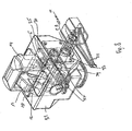
- a locking device 1 is shown therein for locking an ISO standardized corner fitting 2 of a freight container.
- the locking device 1 comprises locking means 3 which are adjustable between an opened position represented in Fig. 1 and a closed position represented in Fig. 2 .
- the locking means can freely pass an opening 4 of the corner fitting 2.
- the locking means 3 hook behind a wall of the corner fitting 2 surrounding the opening 4.
- the locking device 1 comprises biasing means 6 which bias the locking means 3 towards the opened position.
- the locking device 1 further comprises operating means 7 which, upon placement of a container on the locking device 1, and upon removal of a container from the locking device 1, cooperate with an outside surface 8 of the wall 5 of a corner fitting 2. Owing to this cooperation, the operating means 7 are adjustable between an unloaded initial position shown in Fig. 1 , and an end position loaded by the weight of the container shown in Fig. 2 .
- the locking device 1 further comprises an adjusting mechanism 9 which couples the locking means 3 and the operating means 7.
- the coupling is such that the initial position of the operating means 7 corresponds to the opened position of the locking means 3, and that the end position of the operating means 7 corresponds to the closed position of the locking means 3.
- Figs. 1 and 2 it is shown that, upon placement of a corner fitting 2 of a container on the locking device 1, the weight load of the container, indicated with arrow 10, energizes the locking means 3 against the action of the bias towards the closed position.
- the opposing biasing means 6 store energy, with which, upon removal of the container, the locking means 3 can be brought to the opened position.
- the locking device 1 is further provided with securing means 11 for securing the locking means 3 in the closed position.
- Figs. 1 and 2 show that the adjusting mechanism 9 comprises a scissor mechanism.
- the scissor mechanism comprises two legs 13, 14 crossing at the location of a pivot 12.
- the pivot 11 is slideably received in slotted holes 15 recessed in the inner box 16 of the adjusting mechanism 9.
- the locking means 3 are formed by free ends 17, 18 of the legs 13, 14 of the scissor mechanism.
- the locking means 3 comprise clamping surfaces 19, 20 provided substantially at right angles to each other on the scissor mechanism.
- the clamping surfaces 19 cooperate with an inside surface 21 of the opening 4 in the wall 5 of the corner fitting 2
- the clamping surfaces 20 cooperate with an inside surface 22 of the wall 5 which surrounds the opening 4 of the corner fitting 2, respectively.
- the leg parts 13a, 14a of the scissors extending between the pivot 12 and the clamping surfaces 19, 20 provided with free ends 17, 18, are longer than the legs parts 13b, 14b extending between the pivot 12 and the opposite free ends 23, 24.
- the operating means 7, designed here as a box-shaped outer housing, are provided with a first contact surface 25 for cooperation with an outside surface 8 of the wall 5 of the corner fitting 2.
- the operating means are further provided with a second contact surface 27 which engages the pivot 12 of the scissor mechanism.
- the securing means 11 comprise a pin 28 which is adjustable between a securing position shown in Fig. 2 , in which the pin 28 blocks movement of the legs 13, 14 of the scissor mechanism, and a releasing position (not shown) in which the pin 28 releases movement of the legs 13, 14.
- the pin 28 is towards the securing position under the action of a spring 29. What can be achieved as a result of this is that the securing mechanism automatically locks the locking device 1 as soon as the locking means 3 are in the closed position. The locking can then for instance be released by withdrawing the pin 28 against the action of the spring 29 and having it return after the container is released from the locking device 1.
- a second embodiment of the locking device 1 is shown.
- the operating means are designed as operating projections 30.
- the housing 31 has the function of inside box 16 of the adjusting mechanism 9 of Figs. 1 and 2 .
- Both the housing 31 and the operating projections 30 are provided with slotted holes 15 in which the pivot 12 is received so as to be slideable.
- Pin 28 locks the short leg parts 13b, 14b in the securing position. Pin 28 is under the action of spring 29 if clamp 32 is in folded-in condition, as shown in Fig. 4 .
- a third embodiment of the locking device 1 is represented.
- the operating means 7 are formed by the operating projections 30.
- the adjusting mechanism 9 comprises the pivot 12 which is received in a slotted hole 15 of the operating projections 30 and in a matching hole in the scissor legs 13, 14.
- the pivot 12 is received so as to be slideable in the slotted hole 15. From the opened position, shown in Fig. 5 , the operating projections 30 are pressed down by the weight of the container in a direction according to the arrow 10, and the pivot 12 also moves downwards in the slotted holes 15.
- the scissor legs 13 and 14 are pressed against the force of the biasing means 6 to the closed position shown in Fig. 6 , so that the free ends 17, 18 hook behind a wall 5 of a corner fitting of the container.
- the locking device 1 In the closed position, the locking device 1 is secured in vertical direction by the securing means 11.
- the securing means 11 comprise the pin 28 with spring 29 and clamp 32, and a key hole 33.
- the securing means 11 are adjustable between a securing position, shown in Fig. 8 , and a releasing position, shown in Fig. 7 .
- the clamp 32 is folded in, as shown in Fig. 8 .
- the operating projections 30 are pressed down and the narrower part 34 of the pin 28 has come loose from the narrow part of the key hole 33, and the pin is axially displaced under the spring action. Movement of the operating projections 30 relative to the housing 31 is thus prevented and the locking device 1 is secured.
- the locking means 3 are prevented from moving freely from the closed position, in which they hook behind the opening of the wall 5 surrounding the corner fitting 2, towards the opened position, in which they can freely pass the opening of the corner fitting 5, by means of blocking the movement of the operating means 7.
- the securing means 11 are put into the releasing position, as shown in Fig. 7 , by folding out the clamp 32.
- the pin 28 can be provided at the end opposite the clamp with a groove for cooperation with a projection of the housing 31. As a result, in the securing position, the pin 28 is connected to the housing 31 so as to be secured against rotation.
- the locking device 1 is also provided with compensating means 37, designed here as resilient lips.
- the resilient lips can be designed as leaf springs.
- the compensating means 37 are located between the free ends 23, 24 of the scissor legs 13, 14, and the housing 31.
- the compensating means 39 compensate for a variation in thickness of the wall 5 of the corner fitting 2 of the container, so that clearance between the clamping surfaces 19, 20 of the scissor legs 13, 14 and the wall 5 of the corner fitting 2 of the container is prevented.
- the operating mechanism can be designed as a substantially T-shaped bolt, wherein a lying part of the bolt forms the actual locking element and wherein the upright part of the bolt forms a rotatably mounted central axis.
- a screw spring may be provided, with an entering end thereof coupled to an operating plate mounted for translation along the central axis. An exiting end can then be coupled to the central axis.
- the central axis can further be connected, with the aid or a screw thread with coarse pitch, to a housing of the locking device, so that upon rotation of the bolt about its central axis, the lying part of the locking element moves downwards.
- the locking element when a corner fitting is placed on the operating plate, the locking element can first pass the elongated locking opening in the wall of the corner fitting. Through the axial movement of the operating plate, the spring will be compressed so that the exiting end applies a force to the locking element for rotating it about its axis. After the locking element has passed the locking opening, the locking element can turn, under the action of the spring, to a position in which it can hook behind the wall surrounding the locking opening. After an initial rotation, the screw thread can then be brought into engagement between the central axis and the housing, so that upon further rotation, the locking element is tightened. Naturally, it is also possible to provide the locking element with a wedge surface instead of with screw thread.
Landscapes
- Engineering & Computer Science (AREA)
- Mechanical Engineering (AREA)
- Transportation (AREA)
- Lock And Its Accessories (AREA)
- Closures For Containers (AREA)
- Fittings On The Vehicle Exterior For Carrying Loads, And Devices For Holding Or Mounting Articles (AREA)
- Switch Cases, Indication, And Locking (AREA)
- Refuse Receptacles (AREA)
Claims (15)
- Verriegelungsvorrichtung (1) zur Verriegelung eines nach ISO standardisierten Eckbeschlags (2) eines Frachtcontainers, umfassend:- Verriegelungsmittel (3), welche zwischen einer geöffneten Stellung, in welcher die Verriegelungsmittel (3) unbehindert eine Öffnung (4) des Eckbeschlags (2) passieren können, und einer geschlossenen Stellung, in welcher sich die Verriegelungsmittel (3) hinter der Öffnung einer Wand (5), welche die Öffnung (4) des Eckbeschlags (2) umgibt, verhaken, einstellbar sind;- Betriebsmittel (7), welche bei einer Platzierung eines Containers auf der Verriegelungsvorrichtung (1) durch ein Zusammenwirken mit einer Wand (5) des Eckbeschlags (2) von einer unbelasteten anfänglichen Stellung in eine Endstellung, welche durch das Gewicht des Containers belastet ist, einstellbar sind, und- einen Einstellmechanismus (9), welcher die Verriegelungsmittel (3) und die Betriebsmittel (7) in einer Weise koppelt, so dass die anfängliche Stellung der Betriebsmittel (7) mit der geöffneten Stellung der Verriegelungsmittel (3) korrespondiert und so dass die Endstellung der Betriebsmittel (7) mit der geschlossenen Stellung der Verriegelungsmittel (3) korrespondiert, und so dass bei einer Platzierung eines Eckbeschlags (2) eines Containers auf der Verriegelungsvorrichtung(1) die Gewichtslast des Containers die Verriegelungsmittel (3) zu der geschlossenen Stellung treibt, dadurch gekennzeichnet, dass darüber hinaus Sicherungsmittel (11) vorhanden sind, um die Verriegelungsmittel (3) in der geschlossenen Stellung zu halten.
- Verriegelungsvorrichtung (1) nach Anspruch 1, dadurch gekennzeichnet, dass bei einer Platzierung eines Containers auf der Verriegelungsvorrichtung (1) die Betriebsmittel (7) durch ein Zusammenwirken mit einer Wand (5) des Eckbeschlags (2) zwischen einer unbelasteten anfänglichen Stellung und der Endstellung, welche durch das Gewicht des Containers belastet ist, einstellbar sind.
- Verriegelungsvorrichtung nach Anspruch 2, darüber hinaus umfassend:- Vorspannmittel (6), welche die Verriegelungsmittel (3) zu der geöffneten Stellung vorspannen, so dass bei einer Platzierung eines Eckbeschlags (2) eines Containers auf der Verriegelungsvorrichtung (1) die Gewichtslast des Containers die Verriegelungsmittel (3) gegen die Wirkung der Vorspannung zu der geschlossenen Stellung treibt, und so dass bei einem Entfernen des Containers von der Verriegelungsvorrichtung die Vorspannmittel (6) die Verriegelungsmittel (3) zu der geöffneten Stellung vorspannen.
- Verriegelungsvorrichtung (1) nach Anspruch 3, dadurch gekennzeichnet, dass die Vorspannmittel (6) einen Akkumulator umfassen, um einen Teil der Energie, welche während der Platzierung durch den Container den Betriebsmitteln (7) bereitgestellt wird, zu speichern, und um die Energie mittels der Vorspannkraft wieder während eines Entfernens des Containers den Betriebsmitteln (7) zuzuführen.
- Verriegelungsvorrichtung (1) nach einem der Ansprüche 1 - 4, dadurch gekennzeichnet, dass der Einstellmechanismus (9) einen Scherenmechanismus umfasst.
- Verriegelungsvorrichtung (1) nach Anspruch 5, dadurch gekennzeichnet, dass der Scherenmechanismus zwei Beine (18, 14) umfasst, welche sich an der Stelle eines Drehbolzens (12) kreuzen.
- Verriegelungsvorrichtung (1) nach Anspruch 6, dadurch gekennzeichnet, dass der Drehbolzen (12) gleitend montiert ist.
- Verriegelungsvorrichtung (1) nach einem der vorhergehenden Ansprüche 5 - 7, dadurch gekennzeichnet, dass die Verriegelungsmittel (3) durch freie Enden (17, 18) der Beine (13, 14) der Schere ausgebildet sind.
- Verriegelungsvorrichtung (1) nach Anspruch 8, dadurch gekennzeichnet, dass die Verriegelungsmittel (3) auf den freien Enden (17, 18) der Beine (13, 14) der Schere pro Ende zwei Klemmoberflächen (19, 20), welche im Wesentlichen einen rechten Winkel zueinander für ein Zusammenwirken mit einer inneren Oberfläche (21) einer Öffnung (4) in der Wand (5) der Eckbefestigung (2) bzw. mit einer inneren Oberfläche (22) der Wand (5), welche die Öffnung (4) der Eckbefestigung (2) umgibt, ausbilden.
- Verriegelungsvorrichtung (1) nach einem der Ansprüche 5 - 9, dadurch gekennzeichnet, dass die Beinabschnitte (13a, 14a) der Schere, welche sich zwischen dem Drehbolzen (12) und den freien Enden (17, 18), die mit den Klemmoberflächen (19, 20) versehen sind, erstrecken, länger als die Beinabschnitte (18b, 14b), welche sich zwischen dem Drehbolzen (12) und den gegenüberliegenden freien Enden (23, 24) erstrecken, sind.
- Verriegelungsvorrichtung (1) nach einem der vorhergehenden Ansprüche 5 - 10, dadurch gekennzeichnet, dass die Betriebsmittel (7) mit einer ersten Kontaktoberfläche (25) für ein Zusammenwirken mit einer äußeren Oberfläche (8) der Wand (5) des Eckbeschlags (2) und mit einer zweiten Kontaktoberfläche (27), welche sich mit dem Drehbolzen des Scherenmechanismus in Eingriff befindet, versehen sind.
- Verriegelungsvorrichtung (1) nach einem der vorhergehenden Ansprüche 5 - 11, dadurch gekennzeichnet, dass die Sicherungsmittel (11) einen Stift (28) umfassen, welcher zwischen einer Sicherungsstellung, in welcher der Stift (28) eine Bewegung der Beine (13, 14) der Schere blockiert, und einer freigebenden Stellung, in welcher der Stift (28) eine Bewegung der Beine (13, 14) der Schere freigibt, einstellbar ist.
- Verriegelungsvorrichtung (1) nach Anspruch 12, dadurch gekennzeichnet, dass der Stift (28) unter einer Federwirkung zu der Sicherungsstellung steht.
- Verriegelungsvorrichtung (1) nach Anspruch 13, dadurch gekennzeichnet, dass die Federwirkung mit der Hilfe einer Klammer (32), welche mit einer Anzeige versehen ist, entfernbar ist.
- Fahrzeug, insbesondere ein Containeruntergestell, welches mit einer Anzahl von Verriegelungsvorrichtungen (1) nach einem der vorhergehenden Ansprüche versehen ist.
Priority Applications (2)
| Application Number | Priority Date | Filing Date | Title |
|---|---|---|---|
| PL07747502T PL1937511T3 (pl) | 2006-06-09 | 2007-06-11 | Przyrząd blokujący |
| SI200730102T SI1937511T1 (sl) | 2006-06-09 | 2007-06-11 | Zapahnilna naprava |
Applications Claiming Priority (2)
| Application Number | Priority Date | Filing Date | Title |
|---|---|---|---|
| NL1031973A NL1031973C2 (nl) | 2006-06-09 | 2006-06-09 | Grendelinrichting. |
| PCT/NL2007/050279 WO2007142531A2 (en) | 2006-06-09 | 2007-06-11 | Locking device |
Publications (4)
| Publication Number | Publication Date |
|---|---|
| EP1937511A2 EP1937511A2 (de) | 2008-07-02 |
| EP1937511B1 true EP1937511B1 (de) | 2009-08-26 |
| EP1937511B8 EP1937511B8 (de) | 2009-10-21 |
| EP1937511B2 EP1937511B2 (de) | 2013-10-23 |
Family
ID=37882282
Family Applications (1)
| Application Number | Title | Priority Date | Filing Date |
|---|---|---|---|
| EP07747502.8A Active EP1937511B2 (de) | 2006-06-09 | 2007-06-11 | Sperrvorrichtung |
Country Status (18)
| Country | Link |
|---|---|
| US (1) | US20100290855A1 (de) |
| EP (1) | EP1937511B2 (de) |
| KR (1) | KR101214436B1 (de) |
| CN (1) | CN101500848B (de) |
| AT (1) | ATE440751T1 (de) |
| AU (1) | AU2007256041A1 (de) |
| BR (1) | BRPI0712300A2 (de) |
| CA (1) | CA2654967A1 (de) |
| DE (1) | DE602007002146D1 (de) |
| DK (1) | DK1937511T3 (de) |
| ES (1) | ES2332543T3 (de) |
| MX (1) | MX2008015722A (de) |
| NL (1) | NL1031973C2 (de) |
| PL (1) | PL1937511T3 (de) |
| PT (1) | PT1937511E (de) |
| RU (1) | RU2008152321A (de) |
| SI (1) | SI1937511T1 (de) |
| WO (1) | WO2007142531A2 (de) |
Cited By (6)
| Publication number | Priority date | Publication date | Assignee | Title |
|---|---|---|---|---|
| DE202011050490U1 (de) | 2011-06-20 | 2011-08-19 | Rmm Metternich Mechatronik Gmbh | Horizontalverriegelungsvorrichtung |
| WO2011113430A1 (de) | 2010-03-16 | 2011-09-22 | 1. Rmm Entwicklungsgesellschaft Mbh & Co. Kg | Horizontalverriegelungsvorrichtung zur verriegelung eines containers mit eckbeschlag auf einer ladefläche sowie verriegelungsverfahren dafür |
| DE202010005717U1 (de) | 2010-06-25 | 2011-09-30 | Rmm Metternich Mechatronik Gmbh | Verriegelungsvorrichtung für Container |
| DE102018210359A1 (de) | 2018-06-26 | 2020-01-02 | Zf Friedrichshafen Ag | Verriegelungsvorrichtung zum Verriegeln von Wechselbehältern auf einem Transportfahrzeug |
| WO2022175563A1 (en) | 2021-04-13 | 2022-08-25 | Basf Se | Industrial truck for transporting containers on a support frame |
| DE202021004133U1 (de) | 2021-04-13 | 2022-12-12 | Basf Se | Flurförderer zum Transport von Containern auf einem Tragrahmen |
Families Citing this family (29)
| Publication number | Priority date | Publication date | Assignee | Title |
|---|---|---|---|---|
| TW201002588A (en) * | 2008-07-08 | 2010-01-16 | Universal Global Invest Co Ltd | Automatic-clamp receiving seat capable of preventing container tipping over |
| FI124181B (fi) | 2008-09-16 | 2014-04-15 | Macgregor Fin Oy | Kytkentäväline konttien, erityisesti rahtilaivoissa käytettävien konttien kytkemiseksi |
| EP2445752B1 (de) * | 2009-06-22 | 2015-04-01 | Telair International GmbH | Riegelelement |
| NL2003928C2 (en) * | 2009-12-09 | 2011-06-14 | Logi D B V | LOCKING DEVICE. |
| FI122248B (fi) * | 2010-03-10 | 2011-10-31 | Cargotec Finland Oy | Kytkentäväline konttien, erityisesti rahtilaivoissa käytettävien konttien kytkemiseksi |
| DE102011101228A1 (de) * | 2011-05-11 | 2012-11-15 | Airbus Operations Gmbh | Vorrichtung zur Befestigung einer mobilen Einrichtung in einer Flugzeugkabine |
| DE202012102343U1 (de) * | 2012-06-26 | 2012-07-18 | Rmm Metternich Mechatronik Gmbh | Verriegelungsvorrichtung |
| US9359129B1 (en) * | 2014-01-21 | 2016-06-07 | Peck & Hale, L.L.C. | Automatic lock for cargo container |
| DE102014002310B3 (de) * | 2014-02-19 | 2015-07-09 | Container Quick Lock Nv | Verriegelungsvorrichtung |
| CN103935653B (zh) * | 2014-04-22 | 2016-06-22 | 上海振华重工(集团)股份有限公司 | 集装箱输送工具及其止动装置 |
| TW201623117A (zh) * | 2014-10-27 | 2016-07-01 | 漢斯伯曼發明控股有限公司 | 用以固定運輸貨櫃之方法與系統 |
| CN105667815A (zh) * | 2014-11-19 | 2016-06-15 | 中国航空工业集团公司西安飞机设计研究所 | 一种可定力开锁的货物锁定装置 |
| JP6343251B2 (ja) * | 2015-04-22 | 2018-06-13 | 港製器工業株式会社 | コンテナ固定装置 |
| US9663021B1 (en) | 2016-03-24 | 2017-05-30 | Northrop Grumman Systems Corporation | Expanding clamping twistlock for ISO aperture securement |
| EP3459877B1 (de) * | 2016-05-19 | 2024-05-15 | Minato Seiki Iron Works Co., Ltd. | Anordnung aufweisend eine behältersicherungsvorrichtung |
| US10384592B1 (en) | 2016-08-04 | 2019-08-20 | Peck & Hale, L.L.C. | Automatic lock for cargo container |
| SE540489C2 (en) | 2016-10-27 | 2018-09-25 | Lox Container Tech Ab | A container corner lock for locking a shipping container into position |
| EP3326913B1 (de) * | 2016-11-24 | 2020-02-05 | Airbus Defence and Space, S.A.U. | Antirasselvorrichtung für paletten in frachtflugzeug |
| CN108819033A (zh) * | 2018-07-09 | 2018-11-16 | 蚌埠恒力工贸有限公司 | 一种用于再生胶破碎机的高度调节机构 |
| US11198558B2 (en) * | 2018-07-13 | 2021-12-14 | Artemio Roman | Cylindrical twist lock device |
| CN109159732B (zh) * | 2018-11-06 | 2023-12-26 | 株洲科盟车辆配件有限责任公司 | 一种集装箱锁定装置 |
| FR3091218B1 (fr) * | 2018-12-27 | 2021-12-03 | Renault Sas | Système de verrouillage d’un système embarqué de transport de marchandises et véhicule automobile équipé d’un tel système de verrouillage |
| FR3091270B1 (fr) | 2018-12-27 | 2021-07-02 | Renault Sas | Pied de support et fixation d’un système embarqué de transport de marchandises et système embarqué équipé d’un tel pied |
| CN110171350A (zh) * | 2019-06-05 | 2019-08-27 | 嘉兴菱凡贸易有限公司 | 一种利用重力自动锁定且可自动解锁的集装箱锁 |
| FR3097167B1 (fr) * | 2019-06-17 | 2024-05-24 | Altran Tech | Système de liaison mécanique entre deux modules |
| CN110371507A (zh) * | 2019-07-15 | 2019-10-25 | 中山市科力高自动化设备有限公司 | 一种用于集装箱的锁紧装置 |
| CN110525324B (zh) * | 2019-10-11 | 2023-12-22 | 湖北韵奥科技有限公司 | 一种电子锁定装置 |
| CN113023144B (zh) * | 2021-03-17 | 2023-01-31 | 运易通科技有限公司 | 海洋运输工程用的模块运输箱间的连接挂钩组件 |
| DK181119B8 (en) * | 2021-11-23 | 2023-02-21 | Enabl As | Quick release fastening clamp for securing a component to a vessel and method for operating such fastening clamp when loading and unloading a component from a vessel |
Family Cites Families (10)
| Publication number | Priority date | Publication date | Assignee | Title |
|---|---|---|---|---|
| GB1260364A (en) * | 1969-03-14 | 1972-01-19 | Blair Products S A | Coupling device |
| CA1333479C (en) * | 1989-06-09 | 1994-12-13 | Hans Heidolph | Portable electric fan assembly |
| US5020947A (en) * | 1989-10-03 | 1991-06-04 | Buffers Ab | Automatic locking system |
| EP0507010A1 (de) * | 1991-04-03 | 1992-10-07 | Milorad Kosanovic | Vorrichtung zum Festlegen von Container |
| DE4136973C2 (de) * | 1991-11-11 | 1996-01-18 | Daimler Benz Aerospace Airbus | Vorrichtung zur Lastverriegelung in Flugzeugen |
| US5575599A (en) * | 1994-04-15 | 1996-11-19 | Penz Products, Inc. | Container lock pin system |
| US5613814A (en) * | 1995-07-27 | 1997-03-25 | Jackson; Robert G. | Latching mechanism for securing shipping containers on transport vehicles |
| DE10032566A1 (de) † | 2000-04-06 | 2002-01-17 | Horst Neufingerl | Selbsttätig lösbare Verbindungsbaugruppe, insbesondere zum Verbinden zweier übereinander angeordneter Seefracht-Container |
| ES1053467Y (es) † | 2002-11-15 | 2003-08-01 | Labraca Carlos Manuel Panos | Dispositivo de fijacion para contenedores de transporte. |
| DE102005062339A1 (de) † | 2005-12-24 | 2007-06-28 | METTERNICH, Heinz-Rüdiger | Containerverriegelung |
-
2006
- 2006-06-09 NL NL1031973A patent/NL1031973C2/nl not_active IP Right Cessation
-
2007
- 2007-06-11 AU AU2007256041A patent/AU2007256041A1/en not_active Abandoned
- 2007-06-11 BR BRPI0712300-0A patent/BRPI0712300A2/pt not_active IP Right Cessation
- 2007-06-11 RU RU2008152321/11A patent/RU2008152321A/ru unknown
- 2007-06-11 CN CN2007800260257A patent/CN101500848B/zh active Active
- 2007-06-11 US US12/303,842 patent/US20100290855A1/en not_active Abandoned
- 2007-06-11 DE DE602007002146T patent/DE602007002146D1/de active Active
- 2007-06-11 PL PL07747502T patent/PL1937511T3/pl unknown
- 2007-06-11 WO PCT/NL2007/050279 patent/WO2007142531A2/en active Application Filing
- 2007-06-11 SI SI200730102T patent/SI1937511T1/sl unknown
- 2007-06-11 EP EP07747502.8A patent/EP1937511B2/de active Active
- 2007-06-11 PT PT07747502T patent/PT1937511E/pt unknown
- 2007-06-11 ES ES07747502T patent/ES2332543T3/es active Active
- 2007-06-11 KR KR1020097000396A patent/KR101214436B1/ko not_active IP Right Cessation
- 2007-06-11 DK DK07747502T patent/DK1937511T3/da active
- 2007-06-11 MX MX2008015722A patent/MX2008015722A/es not_active Application Discontinuation
- 2007-06-11 CA CA002654967A patent/CA2654967A1/en not_active Abandoned
- 2007-06-11 AT AT07747502T patent/ATE440751T1/de active
Cited By (10)
| Publication number | Priority date | Publication date | Assignee | Title |
|---|---|---|---|---|
| WO2011113430A1 (de) | 2010-03-16 | 2011-09-22 | 1. Rmm Entwicklungsgesellschaft Mbh & Co. Kg | Horizontalverriegelungsvorrichtung zur verriegelung eines containers mit eckbeschlag auf einer ladefläche sowie verriegelungsverfahren dafür |
| DE202010005717U1 (de) | 2010-06-25 | 2011-09-30 | Rmm Metternich Mechatronik Gmbh | Verriegelungsvorrichtung für Container |
| WO2012022326A1 (de) | 2010-06-25 | 2012-02-23 | Rmm Metternich Mechatronik Gmbh | Verriegelungsvorrichtung für container |
| US8684644B2 (en) | 2010-06-25 | 2014-04-01 | Rmm Metternich Mechatronik Gmbh | Locking device for containers |
| DE202011050490U1 (de) | 2011-06-20 | 2011-08-19 | Rmm Metternich Mechatronik Gmbh | Horizontalverriegelungsvorrichtung |
| EP2537707A1 (de) | 2011-06-20 | 2012-12-26 | RMM Metternich Mechatronik GmbH | Horizontalverriegelungsvorrichtung |
| DE102018210359A1 (de) | 2018-06-26 | 2020-01-02 | Zf Friedrichshafen Ag | Verriegelungsvorrichtung zum Verriegeln von Wechselbehältern auf einem Transportfahrzeug |
| WO2022175563A1 (en) | 2021-04-13 | 2022-08-25 | Basf Se | Industrial truck for transporting containers on a support frame |
| EP4052961A1 (de) | 2021-04-13 | 2022-09-07 | Basf Se | Flurförderzeug zum transportieren von behältern auf einem stützrahmen |
| DE202021004133U1 (de) | 2021-04-13 | 2022-12-12 | Basf Se | Flurförderer zum Transport von Containern auf einem Tragrahmen |
Also Published As
| Publication number | Publication date |
|---|---|
| ATE440751T1 (de) | 2009-09-15 |
| AU2007256041A1 (en) | 2007-12-13 |
| WO2007142531A3 (en) | 2008-01-24 |
| DK1937511T3 (da) | 2010-01-04 |
| EP1937511B2 (de) | 2013-10-23 |
| US20100290855A1 (en) | 2010-11-18 |
| DE602007002146D1 (de) | 2009-10-08 |
| ES2332543T3 (es) | 2010-02-08 |
| RU2008152321A (ru) | 2010-07-20 |
| CN101500848A (zh) | 2009-08-05 |
| PT1937511E (pt) | 2009-12-03 |
| CA2654967A1 (en) | 2007-12-13 |
| MX2008015722A (es) | 2009-06-11 |
| KR20090051156A (ko) | 2009-05-21 |
| NL1031973C2 (nl) | 2007-12-11 |
| KR101214436B1 (ko) | 2012-12-21 |
| SI1937511T1 (sl) | 2010-01-29 |
| EP1937511A2 (de) | 2008-07-02 |
| BRPI0712300A2 (pt) | 2012-01-17 |
| PL1937511T3 (pl) | 2010-01-29 |
| CN101500848B (zh) | 2012-10-03 |
| EP1937511B8 (de) | 2009-10-21 |
| WO2007142531A2 (en) | 2007-12-13 |
Similar Documents
| Publication | Publication Date | Title |
|---|---|---|
| EP1937511B1 (de) | Sperrvorrichtung | |
| JP3629658B2 (ja) | トレーラー用自動コンテナ固定装置 | |
| US5613814A (en) | Latching mechanism for securing shipping containers on transport vehicles | |
| US8684644B2 (en) | Locking device for containers | |
| CA2694248C (en) | Latch device for securing cargo containers together and/or to vehicle decks | |
| CN104684822B (zh) | 锁紧装置 | |
| US20090252568A1 (en) | Automatic Securing Device for Cargo Containers | |
| US7740429B2 (en) | Double locking apparatus for use with a roll-off container transport vehicle | |
| US5464076A (en) | Wheel support for securing a wheel of a wheeled vehicle to a transport vehicle | |
| WO2005095157A1 (en) | Twistlock housing | |
| US6042312A (en) | Cargo bar clamp | |
| US20090242563A1 (en) | Container Lock and Method for Locking of Container Door | |
| US4521044A (en) | Twistlock operator | |
| US6490766B1 (en) | Coupling device including automatic latching lock | |
| CN113661116B (zh) | 用于摩托车顶部箱的关闭和紧固设备 | |
| US20160251021A1 (en) | Connector system for securing stacked containers | |
| CN107531404B (zh) | 集装箱固定装置 | |
| EP3419881B1 (de) | Kojenverriegelungsanordnung für ein fahrzeug | |
| KR0133213B1 (ko) | 자동차 덱크의 게이트 자동개폐장치 | |
| AU2008287392B2 (en) | Latch device for securing cargo containers together and/or to vehicle decks | |
| KR20210107782A (ko) | 차량 탑재 물품 운송 시스템용 잠금 시스템 및 이러한 잠금 시스템이 제공된 자동차 | |
| WO2000030895A1 (en) | Load carrying system for vehicles | |
| EP3094578A1 (de) | Automatische stapelsäule zum lagern und transportieren von elementen | |
| EP2565078A1 (de) | Aufbauelement für eine Ladefläche eines Fahrzeugs |
Legal Events
| Date | Code | Title | Description |
|---|---|---|---|
| PUAI | Public reference made under article 153(3) epc to a published international application that has entered the european phase |
Free format text: ORIGINAL CODE: 0009012 |
|
| 17P | Request for examination filed |
Effective date: 20080411 |
|
| AK | Designated contracting states |
Kind code of ref document: A2 Designated state(s): AT BE BG CH CY CZ DE DK EE ES FI FR GB GR HU IE IS IT LI LT LU LV MC MT NL PL PT RO SE SI SK TR |
|
| AX | Request for extension of the european patent |
Extension state: AL BA HR MK RS |
|
| 17Q | First examination report despatched |
Effective date: 20080924 |
|
| GRAP | Despatch of communication of intention to grant a patent |
Free format text: ORIGINAL CODE: EPIDOSNIGR1 |
|
| GRAS | Grant fee paid |
Free format text: ORIGINAL CODE: EPIDOSNIGR3 |
|
| DAX | Request for extension of the european patent (deleted) | ||
| GRAA | (expected) grant |
Free format text: ORIGINAL CODE: 0009210 |
|
| AK | Designated contracting states |
Kind code of ref document: B1 Designated state(s): AT BE BG CH CY CZ DE DK EE ES FI FR GB GR HU IE IS IT LI LT LU LV MC MT NL PL PT RO SE SI SK TR |
|
| REG | Reference to a national code |
Ref country code: GB Ref legal event code: FG4D |
|
| REG | Reference to a national code |
Ref country code: CH Ref legal event code: EP |
|
| REG | Reference to a national code |
Ref country code: IE Ref legal event code: FG4D |
|
| RAP2 | Party data changed (patent owner data changed or rights of a patent transferred) |
Owner name: CONTAINER QUICK LOCK LUXEMBOURG S.A. |
|
| REF | Corresponds to: |
Ref document number: 602007002146 Country of ref document: DE Date of ref document: 20091008 Kind code of ref document: P |
|
| REG | Reference to a national code |
Ref country code: RO Ref legal event code: EPE |
|
| NLT2 | Nl: modifications (of names), taken from the european patent patent bulletin |
Owner name: CONTAINER QUICK LOCK LUXEMBOURG S.A. Effective date: 20091007 |
|
| REG | Reference to a national code |
Ref country code: PT Ref legal event code: SC4A Free format text: AVAILABILITY OF NATIONAL TRANSLATION Effective date: 20091125 |
|
| REG | Reference to a national code |
Ref country code: SE Ref legal event code: TRGR |
|
| REG | Reference to a national code |
Ref country code: DK Ref legal event code: T3 Ref country code: GR Ref legal event code: EP Ref document number: 20090402936 Country of ref document: GR |
|
| LTIE | Lt: invalidation of european patent or patent extension |
Effective date: 20090826 |
|
| PG25 | Lapsed in a contracting state [announced via postgrant information from national office to epo] |
Ref country code: LT Free format text: LAPSE BECAUSE OF FAILURE TO SUBMIT A TRANSLATION OF THE DESCRIPTION OR TO PAY THE FEE WITHIN THE PRESCRIBED TIME-LIMIT Effective date: 20090826 Ref country code: IS Free format text: LAPSE BECAUSE OF FAILURE TO SUBMIT A TRANSLATION OF THE DESCRIPTION OR TO PAY THE FEE WITHIN THE PRESCRIBED TIME-LIMIT Effective date: 20091226 |
|
| REG | Reference to a national code |
Ref country code: PL Ref legal event code: T3 |
|
| REG | Reference to a national code |
Ref country code: ES Ref legal event code: FG2A Ref document number: 2332543 Country of ref document: ES Kind code of ref document: T3 |
|
| PG25 | Lapsed in a contracting state [announced via postgrant information from national office to epo] |
Ref country code: CY Free format text: LAPSE BECAUSE OF FAILURE TO SUBMIT A TRANSLATION OF THE DESCRIPTION OR TO PAY THE FEE WITHIN THE PRESCRIBED TIME-LIMIT Effective date: 20090826 |
|
| REG | Reference to a national code |
Ref country code: SK Ref legal event code: T3 Ref document number: E 6591 Country of ref document: SK |
|
| REG | Reference to a national code |
Ref country code: HU Ref legal event code: AG4A Ref document number: E007015 Country of ref document: HU |
|
| PG25 | Lapsed in a contracting state [announced via postgrant information from national office to epo] |
Ref country code: EE Free format text: LAPSE BECAUSE OF FAILURE TO SUBMIT A TRANSLATION OF THE DESCRIPTION OR TO PAY THE FEE WITHIN THE PRESCRIBED TIME-LIMIT Effective date: 20090826 |
|
| PLBI | Opposition filed |
Free format text: ORIGINAL CODE: 0009260 |
|
| PLAX | Notice of opposition and request to file observation + time limit sent |
Free format text: ORIGINAL CODE: EPIDOSNOBS2 |
|
| 26 | Opposition filed |
Opponent name: RMM ENTWICKLUNGSGESELLSCHAFT MBH & CO. KG Effective date: 20100525 |
|
| PLAF | Information modified related to communication of a notice of opposition and request to file observations + time limit |
Free format text: ORIGINAL CODE: EPIDOSCOBS2 |
|
| PLBB | Reply of patent proprietor to notice(s) of opposition received |
Free format text: ORIGINAL CODE: EPIDOSNOBS3 |
|
| PG25 | Lapsed in a contracting state [announced via postgrant information from national office to epo] |
Ref country code: MC Free format text: LAPSE BECAUSE OF NON-PAYMENT OF DUE FEES Effective date: 20100630 |
|
| PG25 | Lapsed in a contracting state [announced via postgrant information from national office to epo] |
Ref country code: IT Free format text: LAPSE BECAUSE OF NON-PAYMENT OF DUE FEES Effective date: 20100611 |
|
| PG25 | Lapsed in a contracting state [announced via postgrant information from national office to epo] |
Ref country code: MT Free format text: LAPSE BECAUSE OF FAILURE TO SUBMIT A TRANSLATION OF THE DESCRIPTION OR TO PAY THE FEE WITHIN THE PRESCRIBED TIME-LIMIT Effective date: 20090826 |
|
| PGFP | Annual fee paid to national office [announced via postgrant information from national office to epo] |
Ref country code: GR Payment date: 20110624 Year of fee payment: 5 Ref country code: LV Payment date: 20110610 Year of fee payment: 5 Ref country code: CZ Payment date: 20110609 Year of fee payment: 5 |
|
| PGFP | Annual fee paid to national office [announced via postgrant information from national office to epo] |
Ref country code: RO Payment date: 20110606 Year of fee payment: 5 Ref country code: SI Payment date: 20110607 Year of fee payment: 5 Ref country code: SK Payment date: 20110608 Year of fee payment: 5 Ref country code: FI Payment date: 20110613 Year of fee payment: 5 Ref country code: BG Payment date: 20110613 Year of fee payment: 5 |
|
| PGFP | Annual fee paid to national office [announced via postgrant information from national office to epo] |
Ref country code: HU Payment date: 20110705 Year of fee payment: 5 |
|
| REG | Reference to a national code |
Ref country code: CH Ref legal event code: PL |
|
| PLAB | Opposition data, opponent's data or that of the opponent's representative modified |
Free format text: ORIGINAL CODE: 0009299OPPO |
|
| APAH | Appeal reference modified |
Free format text: ORIGINAL CODE: EPIDOSCREFNO |
|
| APBM | Appeal reference recorded |
Free format text: ORIGINAL CODE: EPIDOSNREFNO |
|
| APBP | Date of receipt of notice of appeal recorded |
Free format text: ORIGINAL CODE: EPIDOSNNOA2O |
|
| APBM | Appeal reference recorded |
Free format text: ORIGINAL CODE: EPIDOSNREFNO |
|
| APBP | Date of receipt of notice of appeal recorded |
Free format text: ORIGINAL CODE: EPIDOSNNOA2O |
|
| R26 | Opposition filed (corrected) |
Opponent name: 1. RMM ENTWICKLUNGSGESELLSCHAFT MBH & CO. KG Effective date: 20100525 |
|
| PG25 | Lapsed in a contracting state [announced via postgrant information from national office to epo] |
Ref country code: LI Free format text: LAPSE BECAUSE OF NON-PAYMENT OF DUE FEES Effective date: 20110630 Ref country code: CH Free format text: LAPSE BECAUSE OF NON-PAYMENT OF DUE FEES Effective date: 20110630 |
|
| APBQ | Date of receipt of statement of grounds of appeal recorded |
Free format text: ORIGINAL CODE: EPIDOSNNOA3O |
|
| PG25 | Lapsed in a contracting state [announced via postgrant information from national office to epo] |
Ref country code: LU Free format text: LAPSE BECAUSE OF NON-PAYMENT OF DUE FEES Effective date: 20100611 |
|
| APBY | Invitation to file observations in appeal sent |
Free format text: ORIGINAL CODE: EPIDOSNOBA2O |
|
| PGFP | Annual fee paid to national office [announced via postgrant information from national office to epo] |
Ref country code: ES Payment date: 20120627 Year of fee payment: 6 |
|
| APCA | Receipt of observations in appeal recorded |
Free format text: ORIGINAL CODE: EPIDOSNOBA4O |
|
| PLAB | Opposition data, opponent's data or that of the opponent's representative modified |
Free format text: ORIGINAL CODE: 0009299OPPO |
|
| PG25 | Lapsed in a contracting state [announced via postgrant information from national office to epo] |
Ref country code: FI Free format text: LAPSE BECAUSE OF NON-PAYMENT OF DUE FEES Effective date: 20120611 Ref country code: CZ Free format text: LAPSE BECAUSE OF NON-PAYMENT OF DUE FEES Effective date: 20120611 |
|
| R26 | Opposition filed (corrected) |
Opponent name: R.E.A. PATENTE GMBH & CO. KG Effective date: 20100525 |
|
| REG | Reference to a national code |
Ref country code: SI Ref legal event code: KO00 Effective date: 20130115 |
|
| REG | Reference to a national code |
Ref country code: SK Ref legal event code: MM4A Ref document number: E 6591 Country of ref document: SK Effective date: 20120611 Ref country code: GR Ref legal event code: ML Ref document number: 20090402936 Country of ref document: GR Effective date: 20130104 |
|
| PGFP | Annual fee paid to national office [announced via postgrant information from national office to epo] |
Ref country code: AT Payment date: 20120613 Year of fee payment: 6 |
|
| PLAB | Opposition data, opponent's data or that of the opponent's representative modified |
Free format text: ORIGINAL CODE: 0009299OPPO |
|
| PG25 | Lapsed in a contracting state [announced via postgrant information from national office to epo] |
Ref country code: RO Free format text: LAPSE BECAUSE OF NON-PAYMENT OF DUE FEES Effective date: 20120611 Ref country code: HU Free format text: LAPSE BECAUSE OF NON-PAYMENT OF DUE FEES Effective date: 20120612 |
|
| R26 | Opposition filed (corrected) |
Opponent name: R.E.A. PATENTE GMBH & CO. KG Effective date: 20100525 |
|
| APBU | Appeal procedure closed |
Free format text: ORIGINAL CODE: EPIDOSNNOA9O |
|
| PG25 | Lapsed in a contracting state [announced via postgrant information from national office to epo] |
Ref country code: SK Free format text: LAPSE BECAUSE OF NON-PAYMENT OF DUE FEES Effective date: 20120611 Ref country code: SI Free format text: LAPSE BECAUSE OF NON-PAYMENT OF DUE FEES Effective date: 20120612 Ref country code: GR Free format text: LAPSE BECAUSE OF NON-PAYMENT OF DUE FEES Effective date: 20130104 |
|
| PGFP | Annual fee paid to national office [announced via postgrant information from national office to epo] |
Ref country code: SE Payment date: 20130619 Year of fee payment: 7 Ref country code: DK Payment date: 20130619 Year of fee payment: 7 |
|
| PGFP | Annual fee paid to national office [announced via postgrant information from national office to epo] |
Ref country code: PT Payment date: 20130611 Year of fee payment: 7 Ref country code: TR Payment date: 20130606 Year of fee payment: 7 Ref country code: PL Payment date: 20130606 Year of fee payment: 7 |
|
| PUAH | Patent maintained in amended form |
Free format text: ORIGINAL CODE: 0009272 |
|
| STAA | Information on the status of an ep patent application or granted ep patent |
Free format text: STATUS: PATENT MAINTAINED AS AMENDED |
|
| 27A | Patent maintained in amended form |
Effective date: 20131023 |
|
| AK | Designated contracting states |
Kind code of ref document: B2 Designated state(s): AT BE BG CH CY CZ DE DK EE ES FI FR GB GR HU IE IS IT LI LT LU LV MC MT NL PL PT RO SE SI SK TR |
|
| REG | Reference to a national code |
Ref country code: DE Ref legal event code: R102 Ref document number: 602007002146 Country of ref document: DE Effective date: 20131023 |
|
| REG | Reference to a national code |
Ref country code: NL Ref legal event code: T3 |
|
| REG | Reference to a national code |
Ref country code: SE Ref legal event code: NAV |
|
| REG | Reference to a national code |
Ref country code: PT Ref legal event code: MP4A Effective date: 20140303 |
|
| REG | Reference to a national code |
Ref country code: AT Ref legal event code: MK05 Ref document number: 440751 Country of ref document: AT Kind code of ref document: T Effective date: 20090826 |
|
| PG25 | Lapsed in a contracting state [announced via postgrant information from national office to epo] |
Ref country code: ES Free format text: LAPSE BECAUSE OF FAILURE TO SUBMIT A TRANSLATION OF THE DESCRIPTION OR TO PAY THE FEE WITHIN THE PRESCRIBED TIME-LIMIT Effective date: 20131023 Ref country code: LV Free format text: LAPSE BECAUSE OF FAILURE TO SUBMIT A TRANSLATION OF THE DESCRIPTION OR TO PAY THE FEE WITHIN THE PRESCRIBED TIME-LIMIT Effective date: 20131023 |
|
| PG25 | Lapsed in a contracting state [announced via postgrant information from national office to epo] |
Ref country code: PT Free format text: LAPSE BECAUSE OF FAILURE TO SUBMIT A TRANSLATION OF THE DESCRIPTION OR TO PAY THE FEE WITHIN THE PRESCRIBED TIME-LIMIT Effective date: 20140311 |
|
| PG25 | Lapsed in a contracting state [announced via postgrant information from national office to epo] |
Ref country code: BG Free format text: LAPSE BECAUSE OF NON-PAYMENT OF DUE FEES Effective date: 20120630 |
|
| PG25 | Lapsed in a contracting state [announced via postgrant information from national office to epo] |
Ref country code: DK Free format text: LAPSE BECAUSE OF FAILURE TO SUBMIT A TRANSLATION OF THE DESCRIPTION OR TO PAY THE FEE WITHIN THE PRESCRIBED TIME-LIMIT Effective date: 20131023 |
|
| PGFP | Annual fee paid to national office [announced via postgrant information from national office to epo] |
Ref country code: IE Payment date: 20140724 Year of fee payment: 8 |
|
| PGFP | Annual fee paid to national office [announced via postgrant information from national office to epo] |
Ref country code: GB Payment date: 20140721 Year of fee payment: 8 Ref country code: FR Payment date: 20140710 Year of fee payment: 8 |
|
| PGFP | Annual fee paid to national office [announced via postgrant information from national office to epo] |
Ref country code: IT Payment date: 20140724 Year of fee payment: 8 |
|
| PG25 | Lapsed in a contracting state [announced via postgrant information from national office to epo] |
Ref country code: LV Free format text: LAPSE BECAUSE OF FAILURE TO SUBMIT A TRANSLATION OF THE DESCRIPTION OR TO PAY THE FEE WITHIN THE PRESCRIBED TIME-LIMIT Effective date: 20120611 |
|
| PG25 | Lapsed in a contracting state [announced via postgrant information from national office to epo] |
Ref country code: LV Free format text: LAPSE BECAUSE OF FAILURE TO SUBMIT A TRANSLATION OF THE DESCRIPTION OR TO PAY THE FEE WITHIN THE PRESCRIBED TIME-LIMIT Effective date: 20120630 |
|
| PG25 | Lapsed in a contracting state [announced via postgrant information from national office to epo] |
Ref country code: IT Free format text: LAPSE BECAUSE OF NON-PAYMENT OF DUE FEES Effective date: 20150611 |
|
| GBPC | Gb: european patent ceased through non-payment of renewal fee |
Effective date: 20150611 |
|
| REG | Reference to a national code |
Ref country code: IE Ref legal event code: MM4A |
|
| REG | Reference to a national code |
Ref country code: FR Ref legal event code: ST Effective date: 20160229 |
|
| PG25 | Lapsed in a contracting state [announced via postgrant information from national office to epo] |
Ref country code: GB Free format text: LAPSE BECAUSE OF NON-PAYMENT OF DUE FEES Effective date: 20150611 Ref country code: IE Free format text: LAPSE BECAUSE OF NON-PAYMENT OF DUE FEES Effective date: 20150611 |
|
| PG25 | Lapsed in a contracting state [announced via postgrant information from national office to epo] |
Ref country code: FR Free format text: LAPSE BECAUSE OF NON-PAYMENT OF DUE FEES Effective date: 20150630 |
|
| PG25 | Lapsed in a contracting state [announced via postgrant information from national office to epo] |
Ref country code: SE Free format text: LAPSE BECAUSE OF FAILURE TO SUBMIT A TRANSLATION OF THE DESCRIPTION OR TO PAY THE FEE WITHIN THE PRESCRIBED TIME-LIMIT Effective date: 20140205 Ref country code: GR Free format text: LAPSE BECAUSE OF FAILURE TO SUBMIT A TRANSLATION OF THE DESCRIPTION OR TO PAY THE FEE WITHIN THE PRESCRIBED TIME-LIMIT Effective date: 20140124 |
|
| PG25 | Lapsed in a contracting state [announced via postgrant information from national office to epo] |
Ref country code: AT Free format text: THE PATENT HAS BEEN ANNULLED BY A DECISION OF A NATIONAL AUTHORITY Effective date: 20090826 |
|
| PG25 | Lapsed in a contracting state [announced via postgrant information from national office to epo] |
Ref country code: PL Free format text: THE PATENT HAS BEEN ANNULLED BY A DECISION OF A NATIONAL AUTHORITY Effective date: 20090826 |
|
| PG25 | Lapsed in a contracting state [announced via postgrant information from national office to epo] |
Ref country code: TR Free format text: LAPSE BECAUSE OF NON-PAYMENT OF DUE FEES Effective date: 20150611 |
|
| PGFP | Annual fee paid to national office [announced via postgrant information from national office to epo] |
Ref country code: DE Payment date: 20230620 Year of fee payment: 17 |
|
| PGFP | Annual fee paid to national office [announced via postgrant information from national office to epo] |
Ref country code: BE Payment date: 20230620 Year of fee payment: 17 |
|
| PGFP | Annual fee paid to national office [announced via postgrant information from national office to epo] |
Ref country code: NL Payment date: 20240418 Year of fee payment: 18 |