EP1936097A1 - Door sealant system - Google Patents
Door sealant system Download PDFInfo
- Publication number
- EP1936097A1 EP1936097A1 EP07405359A EP07405359A EP1936097A1 EP 1936097 A1 EP1936097 A1 EP 1936097A1 EP 07405359 A EP07405359 A EP 07405359A EP 07405359 A EP07405359 A EP 07405359A EP 1936097 A1 EP1936097 A1 EP 1936097A1
- Authority
- EP
- European Patent Office
- Prior art keywords
- door
- guide rail
- web
- groove
- side walls
- Prior art date
- Legal status (The legal status is an assumption and is not a legal conclusion. Google has not performed a legal analysis and makes no representation as to the accuracy of the status listed.)
- Granted
Links
- 239000000565 sealant Substances 0.000 title 1
- 238000007789 sealing Methods 0.000 claims abstract description 42
- 238000013016 damping Methods 0.000 claims description 21
- 238000009423 ventilation Methods 0.000 claims description 12
- 229910052751 metal Inorganic materials 0.000 description 6
- 239000002184 metal Substances 0.000 description 6
- 230000007246 mechanism Effects 0.000 description 5
- 238000009413 insulation Methods 0.000 description 3
- 239000004033 plastic Substances 0.000 description 3
- 229910052782 aluminium Inorganic materials 0.000 description 2
- XAGFODPZIPBFFR-UHFFFAOYSA-N aluminium Chemical compound [Al] XAGFODPZIPBFFR-UHFFFAOYSA-N 0.000 description 2
- 238000009434 installation Methods 0.000 description 2
- 239000002023 wood Substances 0.000 description 2
- 239000011358 absorbing material Substances 0.000 description 1
- 230000009286 beneficial effect Effects 0.000 description 1
- 238000010276 construction Methods 0.000 description 1
- 230000001419 dependent effect Effects 0.000 description 1
- 239000013536 elastomeric material Substances 0.000 description 1
- 238000007373 indentation Methods 0.000 description 1
- 238000004519 manufacturing process Methods 0.000 description 1
- 239000011490 mineral wool Substances 0.000 description 1
- 229920001296 polysiloxane Polymers 0.000 description 1
- 230000037072 sun protection Effects 0.000 description 1
Images

Classifications
-
- E—FIXED CONSTRUCTIONS
- E06—DOORS, WINDOWS, SHUTTERS, OR ROLLER BLINDS IN GENERAL; LADDERS
- E06B—FIXED OR MOVABLE CLOSURES FOR OPENINGS IN BUILDINGS, VEHICLES, FENCES OR LIKE ENCLOSURES IN GENERAL, e.g. DOORS, WINDOWS, BLINDS, GATES
- E06B7/00—Special arrangements or measures in connection with doors or windows
- E06B7/02—Special arrangements or measures in connection with doors or windows for providing ventilation, e.g. through double windows; Arrangement of ventilation roses
-
- E—FIXED CONSTRUCTIONS
- E06—DOORS, WINDOWS, SHUTTERS, OR ROLLER BLINDS IN GENERAL; LADDERS
- E06B—FIXED OR MOVABLE CLOSURES FOR OPENINGS IN BUILDINGS, VEHICLES, FENCES OR LIKE ENCLOSURES IN GENERAL, e.g. DOORS, WINDOWS, BLINDS, GATES
- E06B7/00—Special arrangements or measures in connection with doors or windows
- E06B7/16—Sealing arrangements on wings or parts co-operating with the wings
- E06B7/18—Sealing arrangements on wings or parts co-operating with the wings by means of movable edgings, e.g. draught sealings additionally used for bolting, e.g. by spring force or with operating lever
- E06B7/20—Sealing arrangements on wings or parts co-operating with the wings by means of movable edgings, e.g. draught sealings additionally used for bolting, e.g. by spring force or with operating lever automatically withdrawn when the wing is opened, e.g. by means of magnetic attraction, a pin or an inclined surface, especially for sills
Landscapes
- Engineering & Computer Science (AREA)
- Civil Engineering (AREA)
- Structural Engineering (AREA)
- Specific Sealing Or Ventilating Devices For Doors And Windows (AREA)
Abstract
Description
Die Erfindung betrifft ein Türdichtungssystem gemäss Oberbegriff des Patentanspruchs 1, eine Tür gemäss Oberbegriff des Patentanspruchs 13 bzw. 19, eine Türdichtung gemäss Oberbegriff des Patentanspruchs 17 sowie die Verwendung eines Türdichtungssystems und einer Tür.The invention relates to a door seal system according to the preamble of
Türdichtungen werden in Bereichen eingesetzt, wo ein Schallschutz und ein Schutz vor Zugluft gewünscht ist. Ebenso sollen sie lichtdicht abschliessen. Einfache Türdichtungen sind sogenannte Schleifdichtungen, deren Dichtlippe oder Bürste eine untere Stirnfläche der Türe nach unten überragt.Door seals are used in areas where soundproofing and draft protection is desired. Likewise, they should conclude light-tight. Simple door seals are so-called sliding seals whose sealing lip or brush projects beyond a lower end face of the door.
Ferner sind absenkbare Türdichtungen bekannt, welche üblicherweise im wesentlichen aus einer nach unten offenen, u-förmigen Führungsschiene, einer in der Führungsschiene gehaltenen und relativ zu dieser verschiebbaren Dichtleiste und einem Antriebsmechanismus zum Absenken bzw. zum Anheben der Dichtleiste bestehen. Üblicherweise senkt sich die Dichtleiste automatisch beim Schliessen der Tür ab, indem ein Betätigungsstab zurückgeschoben wird und den mechanischen Absenkmechanismus in Betrieb setzt. Es ist jedoch auch möglich, einen von Hand betätigbaren Antriebsmechanismus vorzusehen. Derartige Türdichtungen sind beispielsweise aus
Es wurde jedoch bereits in
Bei Gebäuden mit kontrollierter Lüftung mag dieses System nicht immer ausreichen. Bei derartigen Gebäuden ist ein Lüftungssystem vorhanden, welches in einen Teil der Räume Luft über Lüftungsschlitze in der Wand, Boden oder Decke einbläst und diese in anderen Räumen über ebenfalls in Wand, Decke oder Boden angeordnete Absaugöffnungen entweicht. Ziel der Lüftung ist es, von aussen eingesaugte Frischluft mittels der nach aussen strömenden gebrauchten Luft zu erwärmen, um so den Energiebedarf zum Heizen der Räume zu minimieren. Der Luftaustausch zwischen den Räumen findet über die Türen statt, so dass diese nicht ganz dicht schliessen dürfen. Üblicherweise wird ein relativ grosser Spalt zwischen unterer Türkante und dem Boden belassen. Dadurch ist jedoch kein Schallschutz vorhanden und Licht schimmert von einem Raum in den anderen. Die Öffnungen gemäss
Es ist deshalb eine Aufgabe der Erfindung, ein Türdichtungssystem und eine Türdichtung für Gebäude mit kontrollierter Lüftung, insbesondere für Minergie® Gebäude zu schaffen, welche auch in bereits bestehende Türen eingebaut werden kann.It is therefore an object of the invention to provide a door seal system and a door seal for buildings with controlled ventilation, in particular for Minergie® buildings, which can also be installed in existing doors.
Diese Aufgabe löst ein Türdichtungssystem mit den Merkmalen des Patentanspruchs 1 sowie eine Türdichtung mit den Merkmalen des Patentanspruchs 17.This object is achieved by a door sealing system having the features of
Das erfindungsgemässe Türdichtungssystem zur Befestigung in einer Nut einer Tür weist eine sich annähernd über die gesamte Breite der Tür erstreckende Führungsschiene auf, welche einen im wesentlichen u-förmigen Querschnitt aufweist, und ein Dichtelement, welches in der Führungsschiene gehalten ist und welches bei geschlossener Tür einen Spalt zwischen der Tür und einem Boden bzw. einer Decke dichtet. Die Führungsschiene besitzt zwei annähernd parallel zueinander verlaufende Seitenwände und einen diese zwei Seitenwände miteinander verbindenden Steg, wobei das Türdichtungssystem einen Luftkanal aufweist, welcher insbesondere bei geschlossener Tür eine Luftzirkulation von einer ersten Seite der Tür zu einer zweiten Seite der Tür, d.h. von einem Raum in einen anderen Raum, gewährleistet und welcher sich auf einer ersten Seite der Führungsschiene an einem vom Steg abgewandten stirnseitigen Ende einer ersten Seitenwand beginnend entlang dieser Seitenwand zum Steg, anschliessend entlang des Stegs und abschliessend entlang der zweiten Seitenwand erstreckt und am vom Steg abgewandten stirnseitigen Ende der zweiten Seitenwand auf einer zweiten Seite der Führungsschiene endet. Das Dichtelement ist ausserhalb des Luftkanals angeordnet und von diesem unabhängig. Die Führungsschiene ist in einer Aussenschiene mit einem im wesentlichen u-förmigen Querschnitt angeordnet, wobei die Aussenschiene und die Führungsschiene in dieselbe Richtung geöffnet sind. Die Seitenwände und der Steg der Führungsschiene sind im wesentlichen in die Aussenschiene eingelassen und der Luftkanal verläuft zwischen Führungsschiene und der Aussenschiene.The inventive door seal system for mounting in a groove of a door has an approximately over the entire width of the door extending guide rail, which has a substantially U-shaped cross-section, and a sealing element which is held in the guide rail and which with the door closed Gap seals between the door and a floor or ceiling. The guide rail has two approximately parallel side walls and a connecting these two side walls interconnecting web, the door seal system having an air duct, which in particular with the door closed air circulation from a first side of the door to a second side of the door, ie from a room in another space, guaranteed and which extends on a first side of the guide rail at a side facing away from the web front end of a first side wall along this side wall to the web, then along the web and finally along the second side wall and facing away from the web end face of the second side wall on a second side of the guide rail ends. The sealing element is arranged outside the air duct and independent of this. The guide rail is arranged in an outer rail with a substantially U-shaped cross-section, wherein the outer rail and the guide rail are opened in the same direction. The side walls and the web of the guide rail are substantially embedded in the outer rail and the air duct extends between the guide rail and the outer rail.
Die Führungsschiene und die Aussenschiene können bereits vor ihrer lagefixierten Befestigung in der Tür miteinander verbunden sein und somit als montagebereites Modul geliefert werden. Sie können jedoch auch einzeln und nacheinander in der Türnut befestigt werden.The guide rail and the outer rail can already be connected to each other before their position-fixed attachment in the door and thus be delivered as a ready-to-mount module. However, they can also be attached individually and successively in the door groove.
Dank der Kombination von Aussenschiene mit Führungsschiene kann das Dichtungssystem in jede Tür, insbesondere in jede Holztür, sogar auch nachträglich eingebaut werden. Die Befestigung und die Montage ist relativ einfach und kann auch von ungelerntem Personal durchgeführt werden.Thanks to the combination of external rail and guide rail, the sealing system can even be retrofitted into any door, especially in any wooden door. The attachment and installation is relatively simple and can be performed by untrained personnel.
Dank dieser Konstruktion kann der Luftkanal genügend gross gewählt werden bzw. an die jeweilige Dimensionierung des Lüftungssystems angepasst werden, um die gewünschte Luftzirkulation zu gewährleisten. Vorteilhaft ist, dass der gesamte Luftkanal versteckt und ohne Beeinträchtigung der Dichtleiste verläuft, so dass derselbe Lichtschutz gegeben ist wie bei Dichtungen für normale Gebäude.Thanks to this construction, the air duct can be chosen large enough or adapted to the respective dimensioning of the ventilation system to ensure the desired air circulation. It is advantageous that the entire air duct hidden and runs without affecting the sealing strip, so that the same sun protection is given as in seals for normal buildings.
Die Führungsschiene und somit die Dichtung sind schmäler und vorzugsweise auch niedriger ausgebildet als die Türnut, in welche diese angeordnet sind. In einer einfachen Ausführungsform ist einfach die Führungsschiene annähernd mittig und beabstandet zum oberen Steg in der Aussenschiene angeordnet, so dass der Luftkanal zwischen Führungsschiene und Innenwände der Aussenschiene gebildet ist. Vorzugsweise ist jedoch mindestens eine Seite des Luftkanals mit einem Schalldämpfungselement versehen. Vorzugsweise ist der Luftkanal jedoch beidseitig mit Schalldämpfungselement versehen, wobei sich diese Elemente über die Seitenwände und die oberen Wände erstrecken.The guide rail and thus the seal are narrower and preferably also formed lower than the door groove in which they are arranged. In a simple embodiment, the guide rail is simply arranged approximately centrally and at a distance from the upper web in the outer rail, so that the air duct is formed between the guide rail and inner walls of the outer rail. Preferably, however, at least one side of the air duct is provided with a sound damping element. Preferably, however, the air duct is provided on both sides with a sound damping element, wherein these elements extend over the side walls and the upper walls.
Die Aussenschiene kann gleich lang ausgebildet sein wie die Führungsschiene. Vorzugsweise ist sie jedoch kürzer ausgebildet, so dass sie im Bereich der seitlichen Stirnflächen der Türe der Führungsschiene nachgeordnet ist.The outer rail can be the same length as the guide rail. Preferably, however, it is shorter, so that it is arranged downstream of the guide rail in the region of the lateral end faces.
Die erfindungsgemässe Türdichtung gemäss Anspruch 17 lässt sich auch ohne Aussenschiene verwenden. Ein Luftkanal und eine einfache Montage der Dichtung sind dank den Befestigungsbügeln trotzdem gewährleistet.The inventive door seal according to claim 17 can also be used without external rail. An air duct and a simple installation of the seal are still guaranteed thanks to the mounting brackets.
Es ist eine weitere Aufgabe der Erfindung, eine Tür zu schaffen, welche möglichst schmal ausgebildet sein kann und trotzdem einen genügenden Luftaustausch zwischen zwei Räumen gewährleistet.It is a further object of the invention to provide a door which can be made as narrow as possible and still ensures a sufficient exchange of air between two rooms.
Diese Aufgabe löst eine Tür mit den Merkmalen gemäss Patentanspruch 13.This object is achieved by a door having the features according to
Da die Nut abgesetzt bzw. gestuft ausgebildet ist und an einem Ende bzw. an beiden stirnseitigen Enden gleich breit und/oder gleich tief wie die Führungsschiene ausgebildet ist, wird kein zusätzlicher Platz für die Befestigung der Führungsschiene in der Nut benötigt. Sie lässt sich auf bekannte Art und Weise, beispielsweise mittels Winkelelementen, montieren. Sie lässt sich auch mit Befestigungsbügeln fixieren. Die abgesetzte Nut weist den weiteren Vorteil auf, dass der Luftkanal stirnseitig nicht sichtbar ist und das Erscheinungsbild im offenen Zustand der Tür nicht beeinträchtigt.Since the groove is discontinuous or stepped and is formed at one end or at both ends of the same width and / or equal deep as the guide rail, no additional space for the attachment of the guide rail in the groove is needed. It can be mounted in a known manner, for example by means of angle elements. It can also be fixed with mounting brackets. The remote groove has the further advantage that the air duct is not visible on the front side and does not affect the appearance in the open state of the door.
Die erfindungsgemässe Tür gemäss Anspruch 13 kann eine Aussenschiene aufweisen. Vorzugsweise ist die Führungsschiene jedoch ohne Aussenschiene in der Nut befestigt. Sie kann mit einer Dichtung gemäss Anspruch 17 versehen sein oder mit einer bekannten Dichtung, welche mit bekannten Mitteln in der Nut befestigt ist. Dadurch lässt sich auf einfache Art und Weise eine Tür schaffen, welche eine Luftzirkulation zwischen den Räumen gewährleistet, ohne dass die Dichtung an sich angepasst werden muss.The inventive door according to
Weitere vorteilhafte Ausführungsformen gehen aus den abhängigen Patentansprüchen hervor.Further advantageous embodiments will become apparent from the dependent claims.
Im folgenden wird der Erfindungsgegenstand anhand von bevorzugten Ausführungsbeispielen, welche in den beiliegenden Zeichnungen dargestellt sind, erläutert. Es zeigen:
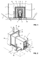
Figur 1- einen Querschnitt durch ein erfindungsgemässes Türdichtungssystem in einer ersten Ausführungsform;
Figur 2- das
System gemäss Figur 1 in perspektivischer Darstellung, wobei Aussenschiene und Tür in je einem Teilschnitt dargestellt sind; Figur 3- eine perspektivische Ansicht des
Systems gemäss Figur 1 von unten; Figur 4- eine perspektivische Ansicht eines erfindungsgemässen Türdichtungs-systems in einer zweiten Ausführungsform;
Figur 5- einen Querschnitt durch ein erfindungsgemässes Türdichtungssystem in einer dritten Ausführungsform;
Figur 6- einen Querschnitt durch ein erfindungsgemässes Türdichtungssystem in einer vierten Ausführungsform,
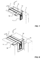
Figur 7- eine perspektivische Ansicht eines erfindungsgemässen Türdichtungs-systems gemäss einer fünften Ausführungsform;
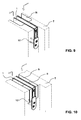
Figur 8- gemäss einer sechsten Ausführungsform;
- Figur 9
- gemäss einer siebten Ausführungsform und
Figur 10- gemäss einer achten Ausführungsform.
- FIG. 1
- a cross section through a door seal system according to the invention in a first embodiment;
- FIG. 2
- the system according to
FIG. 1 in a perspective view, the outer rail and door are each shown in a partial section; - FIG. 3
- a perspective view of the system according to
FIG. 1 from underneath; - FIG. 4
- a perspective view of an inventive door seal system in a second embodiment;
- FIG. 5
- a cross section through a door seal system according to the invention in a third embodiment;
- FIG. 6
- a cross section through a door seal system according to the invention in a fourth embodiment,
- FIG. 7
- a perspective view of an inventive door seal system according to a fifth embodiment;
- FIG. 8
- according to a sixth embodiment;
- FIG. 9
- according to a seventh embodiment and
- FIG. 10
- according to an eighth embodiment.
Das System weist eine Führungsschiene 1 oder Dichtungsgehäuse mit einem im wesentlichen u-förmigen Querschnitt auf, welche nach unten offen ausgebildet ist. Sie weist zwei vorzugsweise annähernd parallel zueinander verlaufende Seitenwände 12 und einen oberen, diese Seitenwände 12 miteinander verbindenden Steg 13 auf. In dieser Führungsschiene 1 ist eine Trägerschiene 2 angeordnet, an welcher eine Dichtleiste 3 befestigt ist. Die Trägerschiene 2 ist mittels eines nicht dargestellten mechanischen Absenkmechanismus beim Schliessen und Öffnen der Tür automatisch absenkbar bzw. anhebbar. Dadurch dichtet die Dichtleiste den verbleibenden Spalt zwischen geschlossener Tür und Fussboden oder Decke. Weist die Dichtleiste 3 seitliche Schenkel auf, so dichtet sie auch seitlich ab. Die Dichtleiste 3 ist vorzugsweise aus einem elastomeren Material, insbesondere aus Kautschuk oder Silikon gefertigt. Die Führungsschiene 1 und die Trägerschiene 2 sind vorzugsweise Strangprofile, vorzugsweise aus Metall und insbesondere aus Aluminium. In der Trägerschiene 2 ist vorzugsweise ein erstes Schalldämpfungselement 4 angeordnet. Dieses besteht vorzugsweise aus einem Filz. Derartige Absenkdichtungen und ihre Absenkmechanismen sind aus dem Stand der Technik bekannt, beispielsweise aus
An den Seitenwänden der Führungsschiene 1 ist abschnittweise, vorzugsweise mindestens im Bereich ihrer zwei Enden, beidseitig eine Haltelasche bzw. ein Befestigungsbügel 10 angeformt. Dies ist insbesondere in
Vorzugsweise sind die Seitenwände 12 abschnittsweise verlängert und bilden ein Winkelelement. Der Bügel 10 kann jedoch auch angeschweisst oder anderweitig an den Seitenwänden 12 befestigt sein. Des weiteren kann die Führungsschiene 1 über ihre gesamte Länge als Hutprofil ausgebildet sein, so dass sich die Bügel 10 über die gesamte Länge der Schiene 1 erstrecken. In diesem Fall müssen jedoch die Bügel 10 mit Schlitzen versehen sein, um die Luftströmung durchzulassen.Preferably, the
Vorzugsweise sind die Bügel 10 jedoch relativ schmal ausgebildet und erstrecken sich nur über kurze Teilbereiche der Schiene. Sie stehen vorzugsweise paarweise und einander gegenüberliegend annähernd senkrecht von den Unterkanten der Seitenwände 12 ab. An den Seitenwänden 12 benachbarten Ende weisen die Bügel 10 Löcher auf, welche von Schrauben oder Nägeln 7 durchsetzt sind. Mittels dieser Nägel 7 oder Schrauben lässt sich die Führungsschiene 1 in der Nut N befestigen, indem sie, wie dies in den
Die Führungsschiene 1 kann jedoch auch auf andere Art und Weise lagefixiert an der Tür befestigt sein. Beispielsweise mittels den bekannten stirnseitigen U-Bügeln, welche an die seitlichen Stirnflächen der Tür angeschraubt werden.However, the
Gemäss
Die Führungsschiene 1 ist erfindungsgemäss in einer Aussenschiene 8 angeordnet, welche selber in der Tür angeordnet ist und somit nicht Teil der Türe sein kann. Die Aussenschiene 8 weist ebenfalls einen im wesentlichen u-förmigen Querschnitt mit zwei annähernd parallel verlaufenden Seitenwänden 80 und einem diese Seitenwände 80 miteinander verbindenden Steg 81 auf, wobei die Aussenschiene 8 und die Führungsschiene 1 in dieselbe Richtung geöffnet sind. Die Seitenwände 12 und der Steg 13 der Führungsschiene 1 sind im wesentlichen in die Aussenschiene 8 eingelassen, d.h. ihre Unterkanten sind vorzugsweise höher oder bündig mit der Aussenschiene, können diese aber auch etwas nach unten überragen. Die Aussenschiene 8 ist ebenfalls vorzugsweise aus einem Strangprofil, insbesondere aus einem Metall, beispielsweise Aluminium, gefertigt. Sie ist breiter und höher ausgebildet als die Führungsschiene, so dass diese auf drei Seiten beabstandet in der Aussenschiene gehalten ist.The
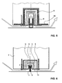
Wie in
Auf der Innenseite der Aussenschiene 8 ist ein drittes Schalldämpfungselement 6 angeordnet. Auch dieses ist optional, aber vorteilhaft. Es weist wiederum vorzugsweise einen u-förmigen Querschnitt auf, erstreckt sich vorzugsweise über die gesamte Länge der Aussenschiene 8 und schmiegt sich an deren Seitenwände 80 und dem Steg 81 an. Das zweite und dritte Schalldämpfungselement 5 und 6 sind vorzugsweise aus Steinwolle, einem Filz oder einem anderen schalldämmenden Material gefertigt. Sie sind vorzugsweise an den jeweiligen Schienen 1, 8 angeklebt. Ihr Querschnitt ist vorzugsweise der Form der Schiene 1, 8 angepasst. Sie können jedoch auch einen davon abweichenden Querschnitt bzw. Ein- und Ausbuchtungen dazu ausweisen.On the inside of the
Zwischen der Aussenschiene 8 und der darin angeordneten Führungsschiene 1 ist ein Spalt vorhanden, welcher auch bei Vorliegen des zweiten und dritten Dämpfungselementes 5, 6 durchgehend vorhanden ist. Mit durchgehend ist gemeint, dass sich der Spalt auf einer ersten Seite der Führungsschiene 1 an einem vom Steg 13 abgewandten stirnseitigen Ende einer ersten Seitenwand 12 beginnend entlang dieser Seitenwand 12 zum Steg 13, anschliessend entlang des Stegs 13 und abschliessend entlang der zweiten der Seitenwände 12 erstreckt und am vom Steg 13 abgewandten stirnseitigen Ende der zweiten Seitenwand 12 auf einer zweiten Seite der Führungsschiene 1 endet. Dieser Spalt bildet einen Luftkanal, welcher somit die eine Seite der Tür T mit der gegenüberliegenden Seite verbindet, wobei das Dichtelement, hier die Absenkdichtung 1, 2, 3, 4 ausserhalb des Luftkanals angeordnet und von diesem unabhängig ist. Der Luftkanal verläuft ausschliesslich zwischen der Führungsschiene 1 und der Aussenschiene 8. Die Tür bzw. das Dichtungssystem können somit so gestaltet sein, dass der Luftkanal ausschliesslich von der unteren bzw. oberen Stirnseite der Tür sichtbar ist. Die durch den Luftkanal geleitete Luftströmung ist in den Figuren mit L bezeichnet, der Spalt zwischen Türunterkante und Boden mit S.Between the
Das zweite und dritte Dämpfungselement 5, 6 verhindern, dass der Luftstrom ein Pfeifgeräusch verursachen kann bzw. dämpfen dieses.The second and third damping
In der Ausführungsform gemäss
In der Ausführungsform gemäss
In der Ausführungsform gemäss
Das Ausführungsbeispiel gemäss
In den Ausführungsformen gemäss den
In der Nut N können wiederum Schalldämpfungselemente 5, 6, beispielsweise in Form von u-förmigen Profilteilen, welche auf der Führungsschiene 1 befestigt, insbesondere angeklebt sind. Das Schalldämpfungselement kann auch in die Nut eingeklebt oder anderweitig befestigt sein.In the groove N, in turn,
In beiden Varianten ist die Führungsschiene 1 mittels der Befestigungsbügel 10 oder - laschen an der unteren Seite der Türdichtung befestigt. Die übrigen, anhand der oben beschriebenen Beispiele erwähnten Merkmale lassen sich auch bei diesen zwei Varianten einsetzen.In both variants, the
In den
in den in den
In
Die abgesetzte Nut eignet sich insbesondere für Holztüren. Das ein- bzw. zweiseitige Verschliessen der Nut mit einem Metall-, Kunststoff oder Holzblock eignet sich insbesondere für Metall- oder Kunststofftüren, lässt sich aber beispielsweise auch in Holztüren verwenden.The offset groove is particularly suitable for wooden doors. The one- or two-sided closure of the groove with a metal, plastic or wood block is particularly suitable for metal or plastic doors, but can also be used for example in wooden doors.
Die hier beschriebenen Dichtungssysteme bzw. Türen mit einem derartigen Dichtungssystemen eignen sich zur Verwendung in einem Gebäude mit kontrollierter Lüftung, insbesondere in einem Minergie® Haus, da sie eine Luftzirkulation von einem Raum in einen anderen Raum auch bei geschlossener Türe ermöglichen.The sealing systems or doors described here with such a sealing system are suitable for use in a building with controlled ventilation, in particular in a Minergie® house, since they allow air to be circulated from one room to another even with the door closed.
- 11
- Führungsschieneguide rail
- 1010
- Befestigungsbügelmounting bracket
- 10'10 '
- Befestigungswinkelmounting brackets
- 1111
- Rasterelementeraster elements
- 1212
- Seitenwändeside walls
- 1313
- Stegweb
- 22
- Trägerschienesupport rail
- 33
- Dichtleistesealing strip
- 3'3 '
- SchleifdichtungContact sealing
- 44
- erstes Dämpfungselementfirst damping element
- 55
- zweites Dämpfungselementsecond damping element
- 66
- drittes Dämpfungselementthird damping element
- 6060
- Winkelangle
- 77
- Nagelnail
- 7'7 '
- Nagelnail
- 88th
- Aussenschieneouter rail
- 8080
- Seitenwändeside walls
- 8181
- Stegweb
- TT
- Türdoor
- NN
- Nutgroove
- SS
- Spaltgap
- LL
- Luftströmungairflow
- BB
- Blockblock
Claims (21)
wobei das Türdichtungssystem umfasst:
wobei ein Luftkanal zwischen Nut und Führungsschiene vorhanden ist, welcher eine Luftzirkulation von einer ersten Seite der Tür zur anderen Seite der Tür gewährleistet und welcher sich auf einer ersten Seite der Führungsschiene (1) an einem vom Steg abgewandten unteren stirnseitigen Ende einer ersten der Seitenwände (12) beginnend entlang dieser Seitenwand (12) zum Steg (13), anschliessend entlang des Stegs (13) und abschliessend entlang der zweiten der Seitenwände (12) erstreckt und am vom Steg (13) abgewandten unteren stirnseitigen Ende der zweiten Seitenwand (12) auf einer zweiten Seite der Führungsschiene (1) endet, wobei das Dichtelement (3, 3') ausserhalb des Luftkanals angeordnet und von diesem unabhängig ist, wobei die Nut (N) mindestens über einen Teilbereich breiter und tiefer ausgebildet ist als die Führungsschiene (1), dadurch gekennzeichnet, dass die Nut (N) mindestens an einem stirnseitigen Ende, vorzugsweise an beiden stirnseitigen Enden der Tür eine Breite und/oder Tiefe aufweist, welche im wesentlichen der Breite und/oder Tiefe der Führungsschiene (1) entspricht.Door with a door sealing system which is fixed in a groove of the door (T),
wherein the door seal system comprises:
wherein an air channel between the groove and guide rail is provided, which ensures air circulation from a first side of the door to the other side of the door and which on a first side of the guide rail (1) at a side facing away from the web lower front end of a first of the side walls ( 12) starting along this side wall (12) to the web (13), then along the web (13) and finally along the second of the side walls (12) and on the web (13) facing away from the lower end face of the second side wall (12) on a second side of the guide rail (1) terminates, wherein the sealing element (3, 3 ') outside the air duct and is independent of this, wherein the groove (N) at least over a partial area is wider and deeper than the guide rail (1 ), characterized in that the groove (N) at least at one end face, preferably at both front ends of the door a width u nd / or depth which substantially corresponds to the width and / or depth of the guide rail (1).
Applications Claiming Priority (1)
| Application Number | Priority Date | Filing Date | Title |
|---|---|---|---|
| CH20652006 | 2006-12-19 |
Publications (2)
| Publication Number | Publication Date |
|---|---|
| EP1936097A1 true EP1936097A1 (en) | 2008-06-25 |
| EP1936097B1 EP1936097B1 (en) | 2015-02-11 |
Family
ID=38458256
Family Applications (1)
| Application Number | Title | Priority Date | Filing Date |
|---|---|---|---|
| EP20070405359 Active EP1936097B1 (en) | 2006-12-19 | 2007-12-18 | Door sealant system |
Country Status (1)
| Country | Link |
|---|---|
| EP (1) | EP1936097B1 (en) |
Cited By (10)
| Publication number | Priority date | Publication date | Assignee | Title |
|---|---|---|---|---|
| CH701232A1 (en) * | 2009-06-09 | 2010-12-15 | Planet Gdz Ag | Door seal system. |
| WO2013044400A1 (en) | 2011-09-26 | 2013-04-04 | Planet Gdz Ag | Building inner wall |
| EP2664741A1 (en) | 2012-05-18 | 2013-11-20 | Planet GDZ AG | Door sealant system |
| EP2824271A1 (en) | 2013-07-08 | 2015-01-14 | Planet GDZ AG | Door sealant system |
| DE202014101295U1 (en) | 2014-03-20 | 2015-07-01 | Athmer Ohg | Sealing for doors for sealing an air gap between a door leaf on the one hand and a door frame, a floor, a ceiling, a fall or the like. on the other hand |
| EP2450520B1 (en) | 2010-11-04 | 2018-09-26 | Beat Kegel | Controlled ventilation system for a building via a door element |
| JP2020094491A (en) * | 2020-03-19 | 2020-06-18 | 大和ハウス工業株式会社 | door |
| EP3770370A1 (en) | 2019-07-23 | 2021-01-27 | ASSA ABLOY (Schweiz) AG | Door seal arrangement |
| EP4001578A1 (en) * | 2020-11-11 | 2022-05-25 | Panelia Woods Oy | Splash guard arrangement for a door, a door comprising a splash guard arrangement and a method for arranging a splash guard arrangement in a door |
| US11480011B2 (en) | 2012-09-04 | 2022-10-25 | Mondernfold, Inc. | Panel seal systems |
Citations (7)
| Publication number | Priority date | Publication date | Assignee | Title |
|---|---|---|---|---|
| EP0338974A2 (en) | 1988-04-19 | 1989-10-25 | " Planet" Matthias Jaggi | Sealing-arrangement for doors without sill |
| EP0509961A1 (en) | 1991-04-17 | 1992-10-21 | Planet MJT AG | Sealing arrangement, particularly for door wings |
| JPH08284546A (en) * | 1995-04-11 | 1996-10-29 | Sekisui Chem Co Ltd | Ventilated sound insulating door |
| JP2000110455A (en) | 1998-10-06 | 2000-04-18 | Kubota House Corp | Ventilating and sound insulating structure for door part |
| DE29916090U1 (en) | 1999-09-14 | 2001-02-08 | Hahn Gmbh & Co Kg Dr | Floor seal for a door |
| EP1233137A2 (en) * | 2001-02-15 | 2002-08-21 | Planet GDZ AG | Device for sealing the lower edge of a door without a threshold |
| EP1498569A1 (en) | 2003-07-17 | 2005-01-19 | Planet GDZ AG | Door seal |
-
2007
- 2007-12-18 EP EP20070405359 patent/EP1936097B1/en active Active
Patent Citations (7)
| Publication number | Priority date | Publication date | Assignee | Title |
|---|---|---|---|---|
| EP0338974A2 (en) | 1988-04-19 | 1989-10-25 | " Planet" Matthias Jaggi | Sealing-arrangement for doors without sill |
| EP0509961A1 (en) | 1991-04-17 | 1992-10-21 | Planet MJT AG | Sealing arrangement, particularly for door wings |
| JPH08284546A (en) * | 1995-04-11 | 1996-10-29 | Sekisui Chem Co Ltd | Ventilated sound insulating door |
| JP2000110455A (en) | 1998-10-06 | 2000-04-18 | Kubota House Corp | Ventilating and sound insulating structure for door part |
| DE29916090U1 (en) | 1999-09-14 | 2001-02-08 | Hahn Gmbh & Co Kg Dr | Floor seal for a door |
| EP1233137A2 (en) * | 2001-02-15 | 2002-08-21 | Planet GDZ AG | Device for sealing the lower edge of a door without a threshold |
| EP1498569A1 (en) | 2003-07-17 | 2005-01-19 | Planet GDZ AG | Door seal |
Cited By (19)
| Publication number | Priority date | Publication date | Assignee | Title |
|---|---|---|---|---|
| CH701232A1 (en) * | 2009-06-09 | 2010-12-15 | Planet Gdz Ag | Door seal system. |
| WO2010142053A1 (en) * | 2009-06-09 | 2010-12-16 | Planet Gdz Ag | Door sealing system |
| EP2450520B1 (en) | 2010-11-04 | 2018-09-26 | Beat Kegel | Controlled ventilation system for a building via a door element |
| WO2013044400A1 (en) | 2011-09-26 | 2013-04-04 | Planet Gdz Ag | Building inner wall |
| WO2013171075A1 (en) | 2012-05-18 | 2013-11-21 | Planet Gdz Ag | Door sealing system |
| EP2664741A1 (en) | 2012-05-18 | 2013-11-20 | Planet GDZ AG | Door sealant system |
| US9598895B2 (en) | 2012-05-18 | 2017-03-21 | Planet Gdz Ag | Door sealing system |
| US11591838B2 (en) | 2012-09-04 | 2023-02-28 | Modernfold, Inc. | Panel seal systems |
| US11480011B2 (en) | 2012-09-04 | 2022-10-25 | Mondernfold, Inc. | Panel seal systems |
| EP2824271A1 (en) | 2013-07-08 | 2015-01-14 | Planet GDZ AG | Door sealant system |
| WO2015003942A1 (en) | 2013-07-08 | 2015-01-15 | Planet Gdz Ag | Door sealing system |
| CN104818936B (en) * | 2014-03-20 | 2018-07-17 | 阿特玛无限公司 | Sealing device |
| EP2921634A1 (en) | 2014-03-20 | 2015-09-23 | Athmer oHG | Seal for doors for sealing an air gap between a door wing on the one hand and a door frame, a floor, a ceiling, a lintel or the like on the other hand |
| CN104818936A (en) * | 2014-03-20 | 2015-08-05 | 阿特玛无限公司 | Sealing device |
| DE202014101295U1 (en) | 2014-03-20 | 2015-07-01 | Athmer Ohg | Sealing for doors for sealing an air gap between a door leaf on the one hand and a door frame, a floor, a ceiling, a fall or the like. on the other hand |
| EP3770370A1 (en) | 2019-07-23 | 2021-01-27 | ASSA ABLOY (Schweiz) AG | Door seal arrangement |
| EP3770370B1 (en) * | 2019-07-23 | 2024-01-17 | ASSA ABLOY (Schweiz) AG | Door seal arrangement |
| JP2020094491A (en) * | 2020-03-19 | 2020-06-18 | 大和ハウス工業株式会社 | door |
| EP4001578A1 (en) * | 2020-11-11 | 2022-05-25 | Panelia Woods Oy | Splash guard arrangement for a door, a door comprising a splash guard arrangement and a method for arranging a splash guard arrangement in a door |
Also Published As
| Publication number | Publication date |
|---|---|
| EP1936097B1 (en) | 2015-02-11 |
Similar Documents
| Publication | Publication Date | Title |
|---|---|---|
| EP1936097B1 (en) | Door sealant system | |
| EP2867432B1 (en) | Door sealant system | |
| EP2921634B1 (en) | Seal for doors for sealing an air gap between a door wing on the one hand and a door frame, a floor, a ceiling, a lintel or the like on the other hand | |
| EP2440732B1 (en) | Door sealing system | |
| EP2754843A2 (en) | Mounting assembly for a sunshade and kit for the same | |
| DE4143036A1 (en) | Room ventilator with duct to outside air - is incorporated in window frame head together with sound vibrations suppressor | |
| DE102010052365B4 (en) | Guide rail arrangement for sun protection systems, sun protection system and method for mounting sun protection systems | |
| DE102008020941B4 (en) | Air guiding element for supplying and / or removing air | |
| EP2360340B2 (en) | Door assembly | |
| DE102015014351A1 (en) | Ventilation element for windows with a flap acting as a chicane | |
| CH658900A5 (en) | VENTILATION DEVICE FOR INSTALLATION IN WALL OPENINGS OF BUILDINGS, ESPECIALLY IN WINDOW AND DOOR OPENINGS. | |
| EP2267263B1 (en) | Door seal | |
| DE10214239B4 (en) | Device for ventilation of rooms | |
| CH685357A5 (en) | Room ventilation equipment for installation by window or door | |
| EP2055887A2 (en) | Method for storing or transporting a door seal of a door leaf | |
| CH708369B1 (en) | Fire protection sliding door. | |
| EP1106772A1 (en) | Attachment roller shutter box | |
| EP1382788B1 (en) | Sound-proofing device for a door without a threshold | |
| EP1988248A2 (en) | Seal casing and seal with lateral seal profiles | |
| EP3019684B1 (en) | Door sealing system | |
| DE102006024803A1 (en) | Connector for temporary air conditioning to window or door of building has opening for pipe and with front and side sections extending over seating face | |
| EP3770370B1 (en) | Door seal arrangement | |
| CH693107A5 (en) | Ventilation for building door frame has casing with air duct placed into cavity in door frame profile | |
| DE10130133A1 (en) | door leaf | |
| CH705557A1 (en) | Building inner wall. |
Legal Events
| Date | Code | Title | Description |
|---|---|---|---|
| PUAI | Public reference made under article 153(3) epc to a published international application that has entered the european phase |
Free format text: ORIGINAL CODE: 0009012 |
|
| AK | Designated contracting states |
Kind code of ref document: A1 Designated state(s): AT BE BG CH CY CZ DE DK EE ES FI FR GB GR HU IE IS IT LI LT LU LV MC MT NL PL PT RO SE SI SK TR |
|
| AX | Request for extension of the european patent |
Extension state: AL BA HR MK RS |
|
| RAP1 | Party data changed (applicant data changed or rights of an application transferred) |
Owner name: PLANET GDZ AG |
|
| 17P | Request for examination filed |
Effective date: 20081218 |
|
| 17Q | First examination report despatched |
Effective date: 20090205 |
|
| AKX | Designation fees paid |
Designated state(s): AT BE BG CH CY CZ DE DK EE ES FI FR GB GR HU IE IS IT LI LT LU LV MC MT NL PL PT RO SE SI SK TR |
|
| AXX | Extension fees paid |
Extension state: RS Payment date: 20081218 |
|
| RIN1 | Information on inventor provided before grant (corrected) |
Inventor name: DINTHEER, ANDREAS |
|
| GRAP | Despatch of communication of intention to grant a patent |
Free format text: ORIGINAL CODE: EPIDOSNIGR1 |
|
| INTG | Intention to grant announced |
Effective date: 20131209 |
|
| GRAP | Despatch of communication of intention to grant a patent |
Free format text: ORIGINAL CODE: EPIDOSNIGR1 |
|
| RAP1 | Party data changed (applicant data changed or rights of an application transferred) |
Owner name: PLANET GDZ AG |
|
| INTG | Intention to grant announced |
Effective date: 20140714 |
|
| GRAS | Grant fee paid |
Free format text: ORIGINAL CODE: EPIDOSNIGR3 |
|
| GRAA | (expected) grant |
Free format text: ORIGINAL CODE: 0009210 |
|
| AK | Designated contracting states |
Kind code of ref document: B1 Designated state(s): AT BE BG CH CY CZ DE DK EE ES FI FR GB GR HU IE IS IT LI LT LU LV MC MT NL PL PT RO SE SI SK TR |
|
| AX | Request for extension of the european patent |
Extension state: RS |
|
| REG | Reference to a national code |
Ref country code: GB Ref legal event code: FG4D Free format text: NOT ENGLISH |
|
| REG | Reference to a national code |
Ref country code: CH Ref legal event code: EP |
|
| REG | Reference to a national code |
Ref country code: IE Ref legal event code: FG4D Free format text: LANGUAGE OF EP DOCUMENT: GERMAN |
|
| REG | Reference to a national code |
Ref country code: AT Ref legal event code: REF Ref document number: 709997 Country of ref document: AT Kind code of ref document: T Effective date: 20150315 |
|
| REG | Reference to a national code |
Ref country code: DE Ref legal event code: R096 Ref document number: 502007013715 Country of ref document: DE Effective date: 20150326 |
|
| REG | Reference to a national code |
Ref country code: CH Ref legal event code: NV Representative=s name: ISLER AND PEDRAZZINI AG, CH |
|
| REG | Reference to a national code |
Ref country code: NL Ref legal event code: T3 |
|
| REG | Reference to a national code |
Ref country code: LT Ref legal event code: MG4D |
|
| REG | Reference to a national code |
Ref country code: DE Ref legal event code: R082 Ref document number: 502007013715 Country of ref document: DE Representative=s name: HOEGER, STELLRECHT & PARTNER PATENTANWAELTE MB, DE |
|
| PG25 | Lapsed in a contracting state [announced via postgrant information from national office to epo] |
Ref country code: LT Free format text: LAPSE BECAUSE OF FAILURE TO SUBMIT A TRANSLATION OF THE DESCRIPTION OR TO PAY THE FEE WITHIN THE PRESCRIBED TIME-LIMIT Effective date: 20150211 Ref country code: SE Free format text: LAPSE BECAUSE OF FAILURE TO SUBMIT A TRANSLATION OF THE DESCRIPTION OR TO PAY THE FEE WITHIN THE PRESCRIBED TIME-LIMIT Effective date: 20150211 Ref country code: FI Free format text: LAPSE BECAUSE OF FAILURE TO SUBMIT A TRANSLATION OF THE DESCRIPTION OR TO PAY THE FEE WITHIN THE PRESCRIBED TIME-LIMIT Effective date: 20150211 Ref country code: ES Free format text: LAPSE BECAUSE OF FAILURE TO SUBMIT A TRANSLATION OF THE DESCRIPTION OR TO PAY THE FEE WITHIN THE PRESCRIBED TIME-LIMIT Effective date: 20150211 |
|
| PG25 | Lapsed in a contracting state [announced via postgrant information from national office to epo] |
Ref country code: IS Free format text: LAPSE BECAUSE OF FAILURE TO SUBMIT A TRANSLATION OF THE DESCRIPTION OR TO PAY THE FEE WITHIN THE PRESCRIBED TIME-LIMIT Effective date: 20150611 Ref country code: GR Free format text: LAPSE BECAUSE OF FAILURE TO SUBMIT A TRANSLATION OF THE DESCRIPTION OR TO PAY THE FEE WITHIN THE PRESCRIBED TIME-LIMIT Effective date: 20150512 Ref country code: LV Free format text: LAPSE BECAUSE OF FAILURE TO SUBMIT A TRANSLATION OF THE DESCRIPTION OR TO PAY THE FEE WITHIN THE PRESCRIBED TIME-LIMIT Effective date: 20150211 |
|
| PG25 | Lapsed in a contracting state [announced via postgrant information from national office to epo] |
Ref country code: CZ Free format text: LAPSE BECAUSE OF FAILURE TO SUBMIT A TRANSLATION OF THE DESCRIPTION OR TO PAY THE FEE WITHIN THE PRESCRIBED TIME-LIMIT Effective date: 20150211 Ref country code: SK Free format text: LAPSE BECAUSE OF FAILURE TO SUBMIT A TRANSLATION OF THE DESCRIPTION OR TO PAY THE FEE WITHIN THE PRESCRIBED TIME-LIMIT Effective date: 20150211 Ref country code: EE Free format text: LAPSE BECAUSE OF FAILURE TO SUBMIT A TRANSLATION OF THE DESCRIPTION OR TO PAY THE FEE WITHIN THE PRESCRIBED TIME-LIMIT Effective date: 20150211 Ref country code: RO Free format text: LAPSE BECAUSE OF FAILURE TO SUBMIT A TRANSLATION OF THE DESCRIPTION OR TO PAY THE FEE WITHIN THE PRESCRIBED TIME-LIMIT Effective date: 20150211 Ref country code: DK Free format text: LAPSE BECAUSE OF FAILURE TO SUBMIT A TRANSLATION OF THE DESCRIPTION OR TO PAY THE FEE WITHIN THE PRESCRIBED TIME-LIMIT Effective date: 20150211 |
|
| REG | Reference to a national code |
Ref country code: DE Ref legal event code: R097 Ref document number: 502007013715 Country of ref document: DE |
|
| PG25 | Lapsed in a contracting state [announced via postgrant information from national office to epo] |
Ref country code: PL Free format text: LAPSE BECAUSE OF FAILURE TO SUBMIT A TRANSLATION OF THE DESCRIPTION OR TO PAY THE FEE WITHIN THE PRESCRIBED TIME-LIMIT Effective date: 20150211 |
|
| PLBE | No opposition filed within time limit |
Free format text: ORIGINAL CODE: 0009261 |
|
| STAA | Information on the status of an ep patent application or granted ep patent |
Free format text: STATUS: NO OPPOSITION FILED WITHIN TIME LIMIT |
|
| REG | Reference to a national code |
Ref country code: FR Ref legal event code: PLFP Year of fee payment: 9 |
|
| 26N | No opposition filed |
Effective date: 20151112 |
|
| PG25 | Lapsed in a contracting state [announced via postgrant information from national office to epo] |
Ref country code: SI Free format text: LAPSE BECAUSE OF FAILURE TO SUBMIT A TRANSLATION OF THE DESCRIPTION OR TO PAY THE FEE WITHIN THE PRESCRIBED TIME-LIMIT Effective date: 20150211 |
|
| PG25 | Lapsed in a contracting state [announced via postgrant information from national office to epo] |
Ref country code: BE Free format text: LAPSE BECAUSE OF NON-PAYMENT OF DUE FEES Effective date: 20151231 |
|
| PG25 | Lapsed in a contracting state [announced via postgrant information from national office to epo] |
Ref country code: LU Free format text: LAPSE BECAUSE OF FAILURE TO SUBMIT A TRANSLATION OF THE DESCRIPTION OR TO PAY THE FEE WITHIN THE PRESCRIBED TIME-LIMIT Effective date: 20151218 Ref country code: MC Free format text: LAPSE BECAUSE OF FAILURE TO SUBMIT A TRANSLATION OF THE DESCRIPTION OR TO PAY THE FEE WITHIN THE PRESCRIBED TIME-LIMIT Effective date: 20150211 |
|
| REG | Reference to a national code |
Ref country code: IE Ref legal event code: MM4A |
|
| PG25 | Lapsed in a contracting state [announced via postgrant information from national office to epo] |
Ref country code: IE Free format text: LAPSE BECAUSE OF NON-PAYMENT OF DUE FEES Effective date: 20151218 |
|
| REG | Reference to a national code |
Ref country code: FR Ref legal event code: PLFP Year of fee payment: 10 |
|
| PG25 | Lapsed in a contracting state [announced via postgrant information from national office to epo] |
Ref country code: BG Free format text: LAPSE BECAUSE OF FAILURE TO SUBMIT A TRANSLATION OF THE DESCRIPTION OR TO PAY THE FEE WITHIN THE PRESCRIBED TIME-LIMIT Effective date: 20150211 Ref country code: HU Free format text: LAPSE BECAUSE OF FAILURE TO SUBMIT A TRANSLATION OF THE DESCRIPTION OR TO PAY THE FEE WITHIN THE PRESCRIBED TIME-LIMIT; INVALID AB INITIO Effective date: 20071218 |
|
| PG25 | Lapsed in a contracting state [announced via postgrant information from national office to epo] |
Ref country code: CY Free format text: LAPSE BECAUSE OF FAILURE TO SUBMIT A TRANSLATION OF THE DESCRIPTION OR TO PAY THE FEE WITHIN THE PRESCRIBED TIME-LIMIT Effective date: 20150211 |
|
| PG25 | Lapsed in a contracting state [announced via postgrant information from national office to epo] |
Ref country code: MT Free format text: LAPSE BECAUSE OF FAILURE TO SUBMIT A TRANSLATION OF THE DESCRIPTION OR TO PAY THE FEE WITHIN THE PRESCRIBED TIME-LIMIT Effective date: 20150211 Ref country code: TR Free format text: LAPSE BECAUSE OF FAILURE TO SUBMIT A TRANSLATION OF THE DESCRIPTION OR TO PAY THE FEE WITHIN THE PRESCRIBED TIME-LIMIT Effective date: 20150211 |
|
| REG | Reference to a national code |
Ref country code: FR Ref legal event code: PLFP Year of fee payment: 11 |
|
| PG25 | Lapsed in a contracting state [announced via postgrant information from national office to epo] |
Ref country code: PT Free format text: LAPSE BECAUSE OF FAILURE TO SUBMIT A TRANSLATION OF THE DESCRIPTION OR TO PAY THE FEE WITHIN THE PRESCRIBED TIME-LIMIT Effective date: 20150211 |
|
| REG | Reference to a national code |
Ref country code: DE Ref legal event code: R082 Ref document number: 502007013715 Country of ref document: DE Representative=s name: HOEGER, STELLRECHT & PARTNER PATENTANWAELTE MB, DE |
|
| PGFP | Annual fee paid to national office [announced via postgrant information from national office to epo] |
Ref country code: FR Payment date: 20191220 Year of fee payment: 13 |
|
| PGFP | Annual fee paid to national office [announced via postgrant information from national office to epo] |
Ref country code: AT Payment date: 20201125 Year of fee payment: 14 |
|
| PG25 | Lapsed in a contracting state [announced via postgrant information from national office to epo] |
Ref country code: FR Free format text: LAPSE BECAUSE OF NON-PAYMENT OF DUE FEES Effective date: 20201231 |
|
| REG | Reference to a national code |
Ref country code: AT Ref legal event code: MM01 Ref document number: 709997 Country of ref document: AT Kind code of ref document: T Effective date: 20211218 |
|
| PG25 | Lapsed in a contracting state [announced via postgrant information from national office to epo] |
Ref country code: AT Free format text: LAPSE BECAUSE OF NON-PAYMENT OF DUE FEES Effective date: 20211218 |
|
| PGFP | Annual fee paid to national office [announced via postgrant information from national office to epo] |
Ref country code: CH Payment date: 20230101 Year of fee payment: 16 |
|
| PGFP | Annual fee paid to national office [announced via postgrant information from national office to epo] |
Ref country code: NL Payment date: 20231116 Year of fee payment: 17 |
|
| PGFP | Annual fee paid to national office [announced via postgrant information from national office to epo] |
Ref country code: GB Payment date: 20231109 Year of fee payment: 17 |
|
| PGFP | Annual fee paid to national office [announced via postgrant information from national office to epo] |
Ref country code: IT Payment date: 20231110 Year of fee payment: 17 Ref country code: DE Payment date: 20231107 Year of fee payment: 17 |