EP1233137A2 - Device for sealing the lower edge of a door without a threshold - Google Patents
Device for sealing the lower edge of a door without a threshold Download PDFInfo
- Publication number
- EP1233137A2 EP1233137A2 EP02405114A EP02405114A EP1233137A2 EP 1233137 A2 EP1233137 A2 EP 1233137A2 EP 02405114 A EP02405114 A EP 02405114A EP 02405114 A EP02405114 A EP 02405114A EP 1233137 A2 EP1233137 A2 EP 1233137A2
- Authority
- EP
- European Patent Office
- Prior art keywords
- sealing
- profile
- groove
- side walls
- door
- Prior art date
- Legal status (The legal status is an assumption and is not a legal conclusion. Google has not performed a legal analysis and makes no representation as to the accuracy of the status listed.)
- Granted
Links
Images


Classifications
-
- E—FIXED CONSTRUCTIONS
- E06—DOORS, WINDOWS, SHUTTERS, OR ROLLER BLINDS IN GENERAL; LADDERS
- E06B—FIXED OR MOVABLE CLOSURES FOR OPENINGS IN BUILDINGS, VEHICLES, FENCES OR LIKE ENCLOSURES IN GENERAL, e.g. DOORS, WINDOWS, BLINDS, GATES
- E06B7/00—Special arrangements or measures in connection with doors or windows
- E06B7/16—Sealing arrangements on wings or parts co-operating with the wings
- E06B7/18—Sealing arrangements on wings or parts co-operating with the wings by means of movable edgings, e.g. draught sealings additionally used for bolting, e.g. by spring force or with operating lever
- E06B7/20—Sealing arrangements on wings or parts co-operating with the wings by means of movable edgings, e.g. draught sealings additionally used for bolting, e.g. by spring force or with operating lever automatically withdrawn when the wing is opened, e.g. by means of magnetic attraction, a pin or an inclined surface, especially for sills
- E06B7/21—Sealing arrangements on wings or parts co-operating with the wings by means of movable edgings, e.g. draught sealings additionally used for bolting, e.g. by spring force or with operating lever automatically withdrawn when the wing is opened, e.g. by means of magnetic attraction, a pin or an inclined surface, especially for sills with sealing strip movable in plane of wing
-
- E—FIXED CONSTRUCTIONS
- E06—DOORS, WINDOWS, SHUTTERS, OR ROLLER BLINDS IN GENERAL; LADDERS
- E06B—FIXED OR MOVABLE CLOSURES FOR OPENINGS IN BUILDINGS, VEHICLES, FENCES OR LIKE ENCLOSURES IN GENERAL, e.g. DOORS, WINDOWS, BLINDS, GATES
- E06B7/00—Special arrangements or measures in connection with doors or windows
- E06B7/16—Sealing arrangements on wings or parts co-operating with the wings
- E06B7/22—Sealing arrangements on wings or parts co-operating with the wings by means of elastic edgings, e.g. elastic rubber tubes; by means of resilient edgings, e.g. felt or plush strips, resilient metal strips
- E06B7/23—Plastic, sponge rubber, or like strips or tubes
- E06B7/2314—Plastic, sponge rubber, or like strips or tubes characterised by the material
Definitions
- the invention relates to a device for sealing the lower Face of a thresholdless door according to the preamble of Claim 1 and 9 respectively.
- EP-A-338 974 discloses a lowerable sealing device a thresholdless door.
- a U-shaped or hat-shaped guide profile is inserted in a groove on the underside of a door.
- a sealing strip can be moved vertically in the guide profile guided and operated with a lowering mechanism.
- the sealing strip consists of a support profile and one of its underside outstanding elastomeric sealing profile.
- Patent Abstracts of Japan, vol. 1998, no.14 a similar lowerable door seal, which is a means of Has sound insulation.
- This agent is an insulation body, which is held between two elastomeric sealing lips. The insulation body must therefore be used in the manufacture of the door seal can be assembled in a separate step.
- the present invention has for its object the sealing a device of the type mentioned above Improve sound insulation and still use a door seal to create as few parts as possible.
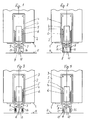
- FIG. 1 to 8 show end views or a vertical section through eight different embodiments.
- the Seals all have a U-shaped or hat-shaped guide profile 3, which is inserted into a groove 4 in the end face 1. in the Guide profile 3, a sealing strip 5 is vertically displaceable.
- the sealing strip 5 consists of an essentially U-shaped, support profile 6 open at the top and an elastomeric sealing profile 7, which in the installed state also U-shaped and after Open at the top and attached to the support profile 6 on both sides is.
- the sealing profile 7 In the part projecting beyond the underside 8 of the support profile 6 of the sealing profile 7, the sealing profile 7 has two side walls 9 and a web 10 connecting them, which when lowered Sealing strip 5 seals against the floor 11.
- FIGS. 1 to 7 the state of the Technique according to EP-A-338 974.
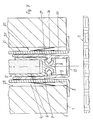
- a strip 15 co-extruded that has different physical properties to the immediately adjacent zones 16 of the side walls 9 or of the web 10.
- the strip 15 can also be used in other ways, for example by means of gluing or a screw connection connect the sealing profile 7.
- the two strips 15 are different thick compared to zones 16 and preferably also unevenly thick.
- the strips 15 are co-extruded and are made of a higher density material than the rest of the sealing profile 7. This measure also diminished the natural frequency. 1 can also be used without combine further with that of FIG. 2.
- the strips 15 are foamed. Foamed material has better sound insulation than Solid material due to increased internal damping. This solution too can be combined with that of FIGS. 1 and / or 2.
- 15 inserts are in the strips 17 e.g. Stone particles, wires, polyester wool etc. co-extruded or inserted, which also has the physical properties the strip 15 change relative to the zones 16, e.g. by changing the density, the natural damping, the natural frequency of the two strips 15 against each other.
- the elements designated 17 in Fig. 4 can also e.g. Be hollow chambers, which the natural vibrations of the side walls 9th out.
- the strip 15 is not molded on the side walls 9 of the sealing profile 7, but as a cord 31 made of a fiber wick, preferably made of polyester wool, formed and in the cavity 32 between the side walls 9, the web 10 and the bottom 8 arranged.
- the cord 31 can e.g. be formed from a cylindrical roll Stripes made of polyester wool fleece. It is expedient that Cord 31 through a thin-walled, flexible hose 33 a plastic film or encased in an elastomer. Most advantageous is the illustrated embodiment in which the hose 33 is integrally formed on the web 10, ie with the sealing profile 7 is co-extruded. Tests have shown that polyester wool in cavity 32 is an excellent insulating material.
- the sealing element 22 can, however, also between the outer surface of the upper web of the guide profile 3 and the bottom of the groove 4 are arranged.
- the sealing element 22 seals against the flanks 23 of the groove 4 or their reason. This will transmit the sound the tolerance-related gap between guide profile 3 and groove 4 effectively prevented.
- this measure has the advantage that the installation tolerances can be chosen much larger.
- the sealing element 22 is an open, elastomeric, thin-walled V-profile, one leg of 24 on the outer surface 20 of the associated leg 25 of the guide profile 3 is glued and the other leg 26 with bias bears against the flank 23.
- This sealing element 22nd can be used alone or in combination with those in the figures 1 to 6 shown co-extruded sealing strips 15 on one Sealing strip be attached.
- the sealing element 22 is not on Sealing profile, but fixed in the groove 4.
Abstract
Description
Die Erfindung betrifft eine Vorrichtung zur Abdichtung der unteren
Stirnfläche einer schwellenlosen Türe gemäss Oberbegriff des
Patentanspruches 1 beziehungsweise 9.The invention relates to a device for sealing the lower
Face of a thresholdless door according to the preamble of
EP-A-338 974 offenbart eine absenkbare Vorrichtung zur Abdichtung einer schwellenlosen Türe. Ein U- oder hutförmiges Führungsprofil ist in einer Nut an der Unterseite einer Türe eingesetzt. Im Führungsprofil ist eine Dichtleiste vertikal beweglich geführt und mit einem Absenkmechanismus betätigbar. Die Dichtleiste besteht aus einem Tragprofil und einem dessen Unterseite überragenden elastomeren Dichtungsprofil.EP-A-338 974 discloses a lowerable sealing device a thresholdless door. A U-shaped or hat-shaped guide profile is inserted in a groove on the underside of a door. A sealing strip can be moved vertically in the guide profile guided and operated with a lowering mechanism. The sealing strip consists of a support profile and one of its underside outstanding elastomeric sealing profile.
Ferner offenbart Patent Abstracts of Japan, vol. 1998, no. 14 eine ähnliche absenkbare Türdichtung, welche ein Mittel zur Schalldämmung aufweist. Dieses Mittel ist ein Isolationskörper, welcher zwischen zwei elastomeren Dichtungslippen gehalten ist. Der Isolationskörper muss somit bei der Fertigung der Türdichtung in einem separaten Arbeitsschritt montiert werden.Patent Abstracts of Japan, vol. 1998, no.14 a similar lowerable door seal, which is a means of Has sound insulation. This agent is an insulation body, which is held between two elastomeric sealing lips. The insulation body must therefore be used in the manufacture of the door seal can be assembled in a separate step.
Der vorliegenden Erfindung liegt die Aufgabe zugrunde, die Abdichtung einer Vorrichtung der eingangs genannten Art bezüglich Schalldämmung zu verbessern und trotzdem eine Türdichtung mit möglichst wenig Teilen zu schaffen.The present invention has for its object the sealing a device of the type mentioned above Improve sound insulation and still use a door seal to create as few parts as possible.
Diese Aufgabe löst eine Vorrichtung mit den Merkmalen des Anspruchs
1 beziehungsweise 9. This object is achieved by a device with the features of the
Nachfolgend werden Ausführungsbeispiele der Erfindung anhand der Zeichnungen erläutert. Darin zeigen Fig. 1 bis 8 Stirnansichten bzw. einen Vertikalschnitt durch acht verschiedene Ausführungsformen.Exemplary embodiments of the invention are described below with reference to the Drawings explained. 1 to 8 show end views or a vertical section through eight different embodiments.
Alle dargestellten Ausführungsbeispiele sind absenkbare Dichtungen
für die untere Stirnfläche 1 von schwellenlosen Türen 2. Die
Dichtungen haben alle ein U- oder hutförmiges Führungsprofil 3,
welches in eine Nut 4 in der Stirnfläche 1 eingesetzt ist. Im
Führungsprofil 3 ist eine Dichtleiste 5 vertikal verschiebbar.
Die Dichtleiste 5 besteht aus einem im wesentlichen U-förmigen,
nach oben offenen Tragprofil 6 und einem elastomeren Dichtungsprofil
7, das im eingebauten Zustand ebenfalls U-förmig und nach
oben offen ausgebildet und beidseitig am Tragprofil 6 befestigt
ist. In dem die Unterseite 8 des Tragprofils 6 überragenden Teil
des Dichtungsprofils 7 hat das Dichtungsprofil 7 zwei Seitenwände
9 und einem diese verbindenden Steg 10, welcher bei abgesenkter
Dichtleiste 5 gegen den Boden 11 abdichtet. Soweit entsprechen
die Ausführungsbeispiele gemäss Fig. 1 bis 7 dem Stand der
Technik gemäss EP-A-338 974.All of the exemplary embodiments shown are lowerable seals
for the
Um die Schalldämmung der Abdichtungsvorrichtung zu verbessern,
ist bei den Ausführungsformen nach Fig. 1 bis 5 in mindestens
einer der Seitenwände 9 des Dichtungsprofils 7, vorzugsweise in
beiden Seitenwänden 9 oder im Steg 10, ein Streifen 15 co-extrudiert,
der unterschiedliche physikalische Eigenschaften hat
zu den unmittelbar benachbarten Zonen 16 der Seitenwände 9 bzw.
des Steges 10. Der Streifen 15 lässt sich auch auf andere Weise,
beispielsweise mittels Kleben oder einer Schraubverbindung, mit
dem Dichtungsprofil 7 verbinden.To improve the soundproofing of the sealing device,
is in the embodiments according to FIGS. 1 to 5 in at least
one of the
Bei der Ausführungsform nach Fig. 1 sind beide Streifen 15 unterschiedlich
dick gegenüber den Zonen 16 und vorzugsweise auch
ungleich dick. Bei dieser Ausführungsform beruht die verbesserte
Schalldämmung auf der erhöhten Masse und daher geringeren Eigenfrequenz
der Streifen 15 und auf der unterschiedlichen Eigenfrequenz
der beiden Seitenwände 9.In the embodiment according to FIG. 1, the two
Bei der Ausführungsform nach Fig. 2 sind die Streifen 15 co-extrudiert
und bestehen aus einem Material höherer Dichte als
der Rest des Dichtungsprofils 7. Auch diese Massnahme vermindert
die Eigenfrequenz. Die Lösung nach Fig. 1 lässt sich auch ohne
weiteres mit jener nach Fig. 2 kombinieren.In the embodiment according to FIG. 2, the
Bei der Ausführungsform nach Fig. 3 sind die Streifen 15 geschäumt.
Geschäumtes Material hat eine bessere Schalldämmung als
Vollmaterial wegen erhöhter Eigendämpfung. Auch diese Lösung
kann mit jener nach Fig. 1 und/oder 2 kombiniert werden.In the embodiment according to FIG. 3, the
Bei der Ausführungsform nach Fig. 4 sind in die Streifen 15 Einlagen
17 z.B. Steinpartikel, Drähte, Polyesterwolle etc. co-extrudiert
oder eingelegt, die ebenfalls die physikalischen Eigenschaften
der Streifen 15 gegenüber den Zonen 16 verändern,
z.B. durch Änderung der Dichte, der Eigendämpfung, der Eigenfrequenz
der beiden Streifen 15 gegeneinander.In the embodiment according to FIG. 4, 15 inserts are in the
Die in Fig. 4 mit 17 bezeichneten Elemente können aber auch z.B. Hohlkammern sein, welche die Eigenschwingungen der Seitenwände 9 verkleinern.The elements designated 17 in Fig. 4 can also e.g. Be hollow chambers, which the natural vibrations of the side walls 9th out.
Das Ausführungsbeispiel nach Fig. 5 entspricht jenem nach Fig.
1, wobei die Streifen 15 in diesem Falle einen dreieckförmigen
Querschnitt haben und sich deren Spitzen überlappen.5 corresponds to that of FIG.
1, the
Beim Ausführungsbeispiel nach Fig. 6 ist der Streifen 15 nicht
an den Seitenwänden 9 des Dichtungsprofils 7 angeformt, sondern
als Schnur 31 aus einem Faserdocht, vorzugsweise aus Polyesterwolle,
ausgebildet und im Hohlraum 32 zwischen den Seitenwänden
9, dem Steg 10 und der Unterseite 8 angeordnet. Die Schnur 31
kann z.B. gebildet sein aus einem zylindrisch aufgerollten
Streifen aus Polyester-Wollvlies. Zweckmässigerweise ist die
Schnur 31 durch einen dünnwandigen, flexiblen Schlauch 33 aus
einer Kunststoffolie oder aus einem Elastomer ummantelt. Am vorteilhaftesten
ist die dargestellte Ausführungsform, in welcher
der Schlauch 33 am Steg 10 angeformt, also mit dem Dichtungsprofil
7 co-extrudiert ist. Versuche haben ergeben, dass Polyesterwolle
im Hohlraum 32 ein ausgezeichnetes Dämmmaterial ist.6, the
Bei der Ausführungsform nach Fig. 7 wird die verbesserte Schalldämmung
dadurch erreicht, dass an der Aussenfläche 20 mindestens
eines der Schenkel 21 des Führungsprofils 3 ein nachgiebiges
Dichtelement 22 befestigt, z.B. angeklebt ist. Das Dichtelement
22 kann jedoch auch zwischen der Aussenfläche des oberen Steges
des Führungsprofils 3 und dem Grund der Nut 4 angeordnet werden.
Das Dichtelement 22 dichtet gegenüber den Flanken 23 der Nut 4
bzw. deren Grund ab. Dadurch wird die Schallübertragung durch
den toleranzbedingten Spalt zwischen Führungsprofil 3 und Nut 4
wirksam verhindert. Ausserdem hat diese Massnahme den Vorteil,
dass die Einbautoleranzen wesentlich grösser gewählt werden können.
Durch die grössere Toleranz für die Nutbreite können die
Fräser zur Herstellung der Nut wesentlich häufiger oder über einen
wesentlich längeren Zeitraum nachgeschliffen werden, was die
Arbeitsgeschwindigkeit und/oder die Lebensdauer der Werkzeuge
erheblich erhöht bzw. verlängert. Beim dargestellten Ausführungsbeispiel
ist das Dichtelement 22 ein nach unten offenes,
elastomeres, dünnwandiges V-Profil, dessen einer Schenkel 24 an
der Aussenfläche 20 des zugehörigen Schenkels 25 des Führungsprofils
3 aufgeklebt ist und dessen anderer Schenkel 26 mit Vorspannung
gegen die Flanke 23 anliegt. Dieses Dichtelement 22
kann für sich alleine oder in Kombination mit den in den Figuren
1 bis 6 dargestellten co-extrudierten Dichtleisten 15 an einer
Dichtleiste angebracht sein. In einer anderen, hier nicht dargestellten
Ausführungsform ist das Dichtelement 22 nicht am
Dichtprofil, sondern in der Nut 4 befestigt.In the embodiment of Fig. 7, the improved sound insulation
achieved in that at least on the
In einer weiteren, in Figur 8 dargestellten Ausführungsform, ist
im Schenkel 25 des Führungsprofils 3 eine Nische 27 vorhanden,
in welcher das Dichtelement 22 befestigt ist. Diese Ausführungsform
ermöglicht die Verwendung eine relativ schmalen Nut 4.In a further embodiment shown in FIG
in the
Claims (10)
Applications Claiming Priority (2)
| Application Number | Priority Date | Filing Date | Title |
|---|---|---|---|
| CH00263/01A CH709210B1 (en) | 2001-02-15 | 2001-02-15 | An apparatus for sealing the lower end face of a threshold-free door. |
| CH2630001 | 2001-02-15 |
Publications (3)
| Publication Number | Publication Date |
|---|---|
| EP1233137A2 true EP1233137A2 (en) | 2002-08-21 |
| EP1233137A3 EP1233137A3 (en) | 2003-10-08 |
| EP1233137B1 EP1233137B1 (en) | 2017-06-07 |
Family
ID=4474733
Family Applications (1)
| Application Number | Title | Priority Date | Filing Date |
|---|---|---|---|
| EP02405114.6A Expired - Lifetime EP1233137B1 (en) | 2001-02-15 | 2002-02-14 | Device for sealing the lower edge of a door without a threshold |
Country Status (2)
| Country | Link |
|---|---|
| EP (1) | EP1233137B1 (en) |
| CH (1) | CH709210B1 (en) |
Cited By (7)
| Publication number | Priority date | Publication date | Assignee | Title |
|---|---|---|---|---|
| EP1936097A1 (en) * | 2006-12-19 | 2008-06-25 | Planet GDZ AG | Door sealant system |
| DE202013104777U1 (en) | 2013-10-24 | 2015-01-26 | Athmer Ohg | Automatic seal with filler in a cavity between a housing and a sealing strip |
| DE202013105687U1 (en) * | 2013-12-13 | 2015-03-16 | Athmer Ohg | Seal comprising at least one mounting bracket and at least one stop for mounting on the edge of a groove in a door leaf or the like. |
| WO2016113149A1 (en) * | 2015-01-15 | 2016-07-21 | Planet Gdz Ag | Seal for a sill-free door |
| DE102017121792A1 (en) * | 2017-09-20 | 2019-03-21 | Athmer Ohg | gap sealing |
| EP3241974B1 (en) | 2003-01-08 | 2019-05-01 | Firma F. Athmer | Assembly for a seal, in particular for a contact seal or for an automatically lowerable floor seal for doors |
| JP2020094491A (en) * | 2020-03-19 | 2020-06-18 | 大和ハウス工業株式会社 | door |
Citations (4)
| Publication number | Priority date | Publication date | Assignee | Title |
|---|---|---|---|---|
| EP0046441A1 (en) | 1980-08-15 | 1982-02-24 | "Planet" Matthias Jaggi | Sealing arrangement on a door without a threshold |
| EP0338974A2 (en) | 1988-04-19 | 1989-10-25 | " Planet" Matthias Jaggi | Sealing-arrangement for doors without sill |
| DE29720854U1 (en) | 1997-11-25 | 1999-04-01 | Kross Manfred | Automatic door-floor seal |
| EP0841457B1 (en) | 1996-11-12 | 2003-07-09 | Firma F. Athmer Sophienhammer | Automatic door sealing device |
Family Cites Families (3)
| Publication number | Priority date | Publication date | Assignee | Title |
|---|---|---|---|---|
| US4519165A (en) * | 1984-01-05 | 1985-05-28 | F. Athmer | Sealing device for the bottom of a door |
| DE3801692A1 (en) * | 1988-01-21 | 1989-07-27 | Mantel Juval | Insulating strip for doors and windows |
| JPH10238251A (en) * | 1997-03-03 | 1998-09-08 | Shibutani:Kk | Sealing device for door bottom |
-
2001
- 2001-02-15 CH CH00263/01A patent/CH709210B1/en not_active IP Right Cessation
-
2002
- 2002-02-14 EP EP02405114.6A patent/EP1233137B1/en not_active Expired - Lifetime
Patent Citations (4)
| Publication number | Priority date | Publication date | Assignee | Title |
|---|---|---|---|---|
| EP0046441A1 (en) | 1980-08-15 | 1982-02-24 | "Planet" Matthias Jaggi | Sealing arrangement on a door without a threshold |
| EP0338974A2 (en) | 1988-04-19 | 1989-10-25 | " Planet" Matthias Jaggi | Sealing-arrangement for doors without sill |
| EP0841457B1 (en) | 1996-11-12 | 2003-07-09 | Firma F. Athmer Sophienhammer | Automatic door sealing device |
| DE29720854U1 (en) | 1997-11-25 | 1999-04-01 | Kross Manfred | Automatic door-floor seal |
Cited By (14)
| Publication number | Priority date | Publication date | Assignee | Title |
|---|---|---|---|---|
| EP3241974B1 (en) | 2003-01-08 | 2019-05-01 | Firma F. Athmer | Assembly for a seal, in particular for a contact seal or for an automatically lowerable floor seal for doors |
| EP1936097A1 (en) * | 2006-12-19 | 2008-06-25 | Planet GDZ AG | Door sealant system |
| DE202013104777U1 (en) | 2013-10-24 | 2015-01-26 | Athmer Ohg | Automatic seal with filler in a cavity between a housing and a sealing strip |
| EP2865839A1 (en) | 2013-10-24 | 2015-04-29 | Athmer oHG | Automatic seal with filler in a cavity between a housing and a sealing strip |
| CN104863478B (en) * | 2013-12-13 | 2019-03-22 | 阿特玛无限公司 | Sealing device |
| DE202013105687U1 (en) * | 2013-12-13 | 2015-03-16 | Athmer Ohg | Seal comprising at least one mounting bracket and at least one stop for mounting on the edge of a groove in a door leaf or the like. |
| CN104863478A (en) * | 2013-12-13 | 2015-08-26 | 阿特玛无限公司 | Seal apparatus |
| CN107407127A (en) * | 2015-01-15 | 2017-11-28 | 普兰特Gdz股份公司 | Seal for the door without threshold |
| AU2016208236B2 (en) * | 2015-01-15 | 2018-12-20 | Planet Gdz Ag | Seal for a sill-free door |
| JP2018505328A (en) * | 2015-01-15 | 2018-02-22 | プラネット ゲーデーツェット アーゲー | Door seal without threshold |
| WO2016113149A1 (en) * | 2015-01-15 | 2016-07-21 | Planet Gdz Ag | Seal for a sill-free door |
| US10533369B2 (en) | 2015-01-15 | 2020-01-14 | Planet Gdz Ag | Seal for a sill-free door |
| DE102017121792A1 (en) * | 2017-09-20 | 2019-03-21 | Athmer Ohg | gap sealing |
| JP2020094491A (en) * | 2020-03-19 | 2020-06-18 | 大和ハウス工業株式会社 | door |
Also Published As
| Publication number | Publication date |
|---|---|
| CH709210B1 (en) | 2015-08-14 |
| EP1233137B1 (en) | 2017-06-07 |
| EP1233137A3 (en) | 2003-10-08 |
Similar Documents
| Publication | Publication Date | Title |
|---|---|---|
| EP0742762B1 (en) | Process for producing and mounting a glass pane with frame, in particular on a vehicle part | |
| DE4309088C2 (en) | Fixed disc for motor vehicles | |
| EP1233137B1 (en) | Device for sealing the lower edge of a door without a threshold | |
| EP0760885B1 (en) | Contraction joint rail | |
| EP1647664A2 (en) | Sliding seal for windows, doors, roller shutters and the like | |
| EP0967357B1 (en) | Sealing profile | |
| DE3009896A1 (en) | SEALING COMPONENT AND LOCKING VALVE WITH SUCH A SEALING COMPONENT | |
| EP1873340A2 (en) | Door system | |
| EP1382788A1 (en) | Sound-proofing device for a door without a threshold | |
| DE60002388T2 (en) | Sealing and guide profiles | |
| DE102022117776B3 (en) | SEALING ELEMENT WITH DRAINAGE AGENT | |
| EP3569807A1 (en) | Joint covering profile | |
| EP0158064A2 (en) | Sealing for a positive-displacement machine for compressible fluids | |
| EP1279791A1 (en) | Drop door seal | |
| EP1762691B1 (en) | Seal for a door or window corner | |
| DE102008046752B3 (en) | Elastic strand seal for wooden windows, wooden doors or the like | |
| DE10350144B3 (en) | Sealing arrangement for a window unit of a motor vehicle comprises a frame sealing profile fixed to a window frame to seal the gap between the window pane and the window frame, and sonic bulkhead devices | |
| DE8131774U1 (en) | "SEALING PROFILE" | |
| EP1518963A1 (en) | Damper | |
| EP3141412B1 (en) | Sealing gasket | |
| DE19532750C1 (en) | Bridge-piece for road-expansion joint | |
| EP2500506B1 (en) | Attachment for clamp holders | |
| DE69811570T2 (en) | Method for improving the sliding properties of a slide on a rail and device for carrying out the method | |
| DE8334610U1 (en) | SEALING STRIP FOR DOOR LEAVES, WINDOW WINGS AND THE LIKE | |
| DE10118825A1 (en) | Foam molding tool for attachment of components onto a vehicle sun roof window includes an insert which holds the component and has seals to prevent foam entry to the tool |
Legal Events
| Date | Code | Title | Description |
|---|---|---|---|
| PUAI | Public reference made under article 153(3) epc to a published international application that has entered the european phase |
Free format text: ORIGINAL CODE: 0009012 |
|
| AK | Designated contracting states |
Kind code of ref document: A2 Designated state(s): AT BE CH CY DE DK ES FI FR GB GR IE IT LI LU MC NL PT SE TR |
|
| AX | Request for extension of the european patent |
Free format text: AL;LT;LV;MK;RO;SI |
|
| PUAL | Search report despatched |
Free format text: ORIGINAL CODE: 0009013 |
|
| AK | Designated contracting states |
Kind code of ref document: A3 Designated state(s): AT BE CH CY DE DK ES FI FR GB GR IE IT LI LU MC NL PT SE TR |
|
| AX | Request for extension of the european patent |
Extension state: AL LT LV MK RO SI |
|
| RIC1 | Information provided on ipc code assigned before grant |
Ipc: 7E 06B 7/23 B Ipc: 7E 06B 7/205 B Ipc: 7E 06B 7/20 A |
|
| 17P | Request for examination filed |
Effective date: 20031103 |
|
| AKX | Designation fees paid |
Designated state(s): AT BE CH CY DE DK ES FI FR GB GR IE IT LI LU MC NL PT SE TR |
|
| AXX | Extension fees paid |
Extension state: LV Payment date: 20031103 Extension state: LT Payment date: 20031103 Extension state: SI Payment date: 20031103 |
|
| RAP1 | Party data changed (applicant data changed or rights of an application transferred) |
Owner name: PLANET GDZ AG |
|
| 17Q | First examination report despatched |
Effective date: 20100323 |
|
| RIN1 | Information on inventor provided before grant (corrected) |
Inventor name: DINTHEER, ANDREAS |
|
| GRAP | Despatch of communication of intention to grant a patent |
Free format text: ORIGINAL CODE: EPIDOSNIGR1 |
|
| TPAC | Observations by third parties |
Free format text: ORIGINAL CODE: EPIDOSNTIPA |
|
| INTG | Intention to grant announced |
Effective date: 20140530 |
|
| RAP1 | Party data changed (applicant data changed or rights of an application transferred) |
Owner name: PLANET GDZ AG |
|
| GRAJ | Information related to disapproval of communication of intention to grant by the applicant or resumption of examination proceedings by the epo deleted |
Free format text: ORIGINAL CODE: EPIDOSDIGR1 |
|
| INTC | Intention to grant announced (deleted) | ||
| TPAC | Observations by third parties |
Free format text: ORIGINAL CODE: EPIDOSNTIPA |
|
| GRAP | Despatch of communication of intention to grant a patent |
Free format text: ORIGINAL CODE: EPIDOSNIGR1 |
|
| INTG | Intention to grant announced |
Effective date: 20151118 |
|
| STAA | Information on the status of an ep patent application or granted ep patent |
Free format text: STATUS: GRANT OF PATENT IS INTENDED |
|
| GRAP | Despatch of communication of intention to grant a patent |
Free format text: ORIGINAL CODE: EPIDOSNIGR1 |
|
| INTG | Intention to grant announced |
Effective date: 20161221 |
|
| GRAS | Grant fee paid |
Free format text: ORIGINAL CODE: EPIDOSNIGR3 |
|
| GRAA | (expected) grant |
Free format text: ORIGINAL CODE: 0009210 |
|
| STAA | Information on the status of an ep patent application or granted ep patent |
Free format text: STATUS: THE PATENT HAS BEEN GRANTED |
|
| AK | Designated contracting states |
Kind code of ref document: B1 Designated state(s): AT BE CH CY DE DK ES FI FR GB GR IE IT LI LU MC NL PT SE TR |
|
| AX | Request for extension of the european patent |
Extension state: LT LV SI |
|
| REG | Reference to a national code |
Ref country code: GB Ref legal event code: FG4D Free format text: NOT ENGLISH |
|
| GRAA | (expected) grant |
Free format text: ORIGINAL CODE: 0009210 |
|
| REG | Reference to a national code |
Ref country code: CH Ref legal event code: EP Ref country code: AT Ref legal event code: REF Ref document number: 899354 Country of ref document: AT Kind code of ref document: T Effective date: 20170615 |
|
| REG | Reference to a national code |
Ref country code: IE Ref legal event code: FG4D Free format text: LANGUAGE OF EP DOCUMENT: GERMAN |
|
| REG | Reference to a national code |
Ref country code: DE Ref legal event code: R096 Ref document number: 50216238 Country of ref document: DE |
|
| REG | Reference to a national code |
Ref country code: CH Ref legal event code: NV Representative=s name: ISLER AND PEDRAZZINI AG, CH |
|
| REG | Reference to a national code |
Ref country code: NL Ref legal event code: MP Effective date: 20170607 |
|
| REG | Reference to a national code |
Ref country code: LT Ref legal event code: MG9D |
|
| PG25 | Lapsed in a contracting state [announced via postgrant information from national office to epo] |
Ref country code: FI Free format text: LAPSE BECAUSE OF FAILURE TO SUBMIT A TRANSLATION OF THE DESCRIPTION OR TO PAY THE FEE WITHIN THE PRESCRIBED TIME-LIMIT Effective date: 20170607 Ref country code: GR Free format text: LAPSE BECAUSE OF FAILURE TO SUBMIT A TRANSLATION OF THE DESCRIPTION OR TO PAY THE FEE WITHIN THE PRESCRIBED TIME-LIMIT Effective date: 20170908 Ref country code: ES Free format text: LAPSE BECAUSE OF FAILURE TO SUBMIT A TRANSLATION OF THE DESCRIPTION OR TO PAY THE FEE WITHIN THE PRESCRIBED TIME-LIMIT Effective date: 20170607 |
|
| PG25 | Lapsed in a contracting state [announced via postgrant information from national office to epo] |
Ref country code: SE Free format text: LAPSE BECAUSE OF FAILURE TO SUBMIT A TRANSLATION OF THE DESCRIPTION OR TO PAY THE FEE WITHIN THE PRESCRIBED TIME-LIMIT Effective date: 20170607 Ref country code: NL Free format text: LAPSE BECAUSE OF FAILURE TO SUBMIT A TRANSLATION OF THE DESCRIPTION OR TO PAY THE FEE WITHIN THE PRESCRIBED TIME-LIMIT Effective date: 20170607 |
|
| REG | Reference to a national code |
Ref country code: FR Ref legal event code: PLFP Year of fee payment: 17 |
|
| REG | Reference to a national code |
Ref country code: DE Ref legal event code: R097 Ref document number: 50216238 Country of ref document: DE |
|
| PLBE | No opposition filed within time limit |
Free format text: ORIGINAL CODE: 0009261 |
|
| STAA | Information on the status of an ep patent application or granted ep patent |
Free format text: STATUS: NO OPPOSITION FILED WITHIN TIME LIMIT |
|
| PG25 | Lapsed in a contracting state [announced via postgrant information from national office to epo] |
Ref country code: DK Free format text: LAPSE BECAUSE OF FAILURE TO SUBMIT A TRANSLATION OF THE DESCRIPTION OR TO PAY THE FEE WITHIN THE PRESCRIBED TIME-LIMIT Effective date: 20170607 |
|
| 26N | No opposition filed |
Effective date: 20180308 |
|
| PG25 | Lapsed in a contracting state [announced via postgrant information from national office to epo] |
Ref country code: MC Free format text: LAPSE BECAUSE OF FAILURE TO SUBMIT A TRANSLATION OF THE DESCRIPTION OR TO PAY THE FEE WITHIN THE PRESCRIBED TIME-LIMIT Effective date: 20170607 |
|
| REG | Reference to a national code |
Ref country code: IE Ref legal event code: MM4A |
|
| REG | Reference to a national code |
Ref country code: BE Ref legal event code: MM Effective date: 20180228 |
|
| PG25 | Lapsed in a contracting state [announced via postgrant information from national office to epo] |
Ref country code: LU Free format text: LAPSE BECAUSE OF NON-PAYMENT OF DUE FEES Effective date: 20180214 |
|
| PG25 | Lapsed in a contracting state [announced via postgrant information from national office to epo] |
Ref country code: IE Free format text: LAPSE BECAUSE OF NON-PAYMENT OF DUE FEES Effective date: 20180214 |
|
| PG25 | Lapsed in a contracting state [announced via postgrant information from national office to epo] |
Ref country code: BE Free format text: LAPSE BECAUSE OF NON-PAYMENT OF DUE FEES Effective date: 20180228 |
|
| REG | Reference to a national code |
Ref country code: AT Ref legal event code: MM01 Ref document number: 899354 Country of ref document: AT Kind code of ref document: T Effective date: 20180214 |
|
| PG25 | Lapsed in a contracting state [announced via postgrant information from national office to epo] |
Ref country code: AT Free format text: LAPSE BECAUSE OF NON-PAYMENT OF DUE FEES Effective date: 20180214 |
|
| PG25 | Lapsed in a contracting state [announced via postgrant information from national office to epo] |
Ref country code: TR Free format text: LAPSE BECAUSE OF FAILURE TO SUBMIT A TRANSLATION OF THE DESCRIPTION OR TO PAY THE FEE WITHIN THE PRESCRIBED TIME-LIMIT Effective date: 20170607 |
|
| PGFP | Annual fee paid to national office [announced via postgrant information from national office to epo] |
Ref country code: DE Payment date: 20200204 Year of fee payment: 19 Ref country code: IT Payment date: 20200128 Year of fee payment: 19 Ref country code: GB Payment date: 20200206 Year of fee payment: 19 |
|
| PG25 | Lapsed in a contracting state [announced via postgrant information from national office to epo] |
Ref country code: PT Free format text: LAPSE BECAUSE OF FAILURE TO SUBMIT A TRANSLATION OF THE DESCRIPTION OR TO PAY THE FEE WITHIN THE PRESCRIBED TIME-LIMIT Effective date: 20170607 |
|
| PGFP | Annual fee paid to national office [announced via postgrant information from national office to epo] |
Ref country code: CH Payment date: 20200213 Year of fee payment: 19 |
|
| PG25 | Lapsed in a contracting state [announced via postgrant information from national office to epo] |
Ref country code: CY Free format text: LAPSE BECAUSE OF FAILURE TO SUBMIT A TRANSLATION OF THE DESCRIPTION OR TO PAY THE FEE WITHIN THE PRESCRIBED TIME-LIMIT Effective date: 20170607 |
|
| PGFP | Annual fee paid to national office [announced via postgrant information from national office to epo] |
Ref country code: FR Payment date: 20200123 Year of fee payment: 19 |
|
| REG | Reference to a national code |
Ref country code: DE Ref legal event code: R119 Ref document number: 50216238 Country of ref document: DE |
|
| GBPC | Gb: european patent ceased through non-payment of renewal fee |
Effective date: 20210214 |
|
| PG25 | Lapsed in a contracting state [announced via postgrant information from national office to epo] |
Ref country code: CH Free format text: LAPSE BECAUSE OF NON-PAYMENT OF DUE FEES Effective date: 20210228 Ref country code: LI Free format text: LAPSE BECAUSE OF NON-PAYMENT OF DUE FEES Effective date: 20210228 |
|
| PG25 | Lapsed in a contracting state [announced via postgrant information from national office to epo] |
Ref country code: DE Free format text: LAPSE BECAUSE OF NON-PAYMENT OF DUE FEES Effective date: 20210901 Ref country code: GB Free format text: LAPSE BECAUSE OF NON-PAYMENT OF DUE FEES Effective date: 20210214 Ref country code: FR Free format text: LAPSE BECAUSE OF NON-PAYMENT OF DUE FEES Effective date: 20210228 |
|
| PG25 | Lapsed in a contracting state [announced via postgrant information from national office to epo] |
Ref country code: IT Free format text: LAPSE BECAUSE OF NON-PAYMENT OF DUE FEES Effective date: 20210214 |