EP3770370B1 - Door seal arrangement - Google Patents
Door seal arrangement Download PDFInfo
- Publication number
- EP3770370B1 EP3770370B1 EP19187846.1A EP19187846A EP3770370B1 EP 3770370 B1 EP3770370 B1 EP 3770370B1 EP 19187846 A EP19187846 A EP 19187846A EP 3770370 B1 EP3770370 B1 EP 3770370B1
- Authority
- EP
- European Patent Office
- Prior art keywords
- seal arrangement
- cavity
- rail
- arrangement according
- web
- Prior art date
- Legal status (The legal status is an assumption and is not a legal conclusion. Google has not performed a legal analysis and makes no representation as to the accuracy of the status listed.)
- Active
Links
- 238000007789 sealing Methods 0.000 claims description 89
- 230000007246 mechanism Effects 0.000 claims description 18
- 230000005540 biological transmission Effects 0.000 claims description 6
- 238000013016 damping Methods 0.000 description 6
- 238000009423 ventilation Methods 0.000 description 5
- 230000004913 activation Effects 0.000 description 3
- 229910052782 aluminium Inorganic materials 0.000 description 2
- XAGFODPZIPBFFR-UHFFFAOYSA-N aluminium Chemical compound [Al] XAGFODPZIPBFFR-UHFFFAOYSA-N 0.000 description 2
- 229910052751 metal Inorganic materials 0.000 description 2
- 239000002184 metal Substances 0.000 description 2
- 239000011358 absorbing material Substances 0.000 description 1
- 230000003213 activating effect Effects 0.000 description 1
- 230000001419 dependent effect Effects 0.000 description 1
- 238000004519 manufacturing process Methods 0.000 description 1
- 239000000463 material Substances 0.000 description 1
- 229920001296 polysiloxane Polymers 0.000 description 1
- 230000000284 resting effect Effects 0.000 description 1
- 230000000007 visual effect Effects 0.000 description 1
Images


Classifications
-
- E—FIXED CONSTRUCTIONS
- E06—DOORS, WINDOWS, SHUTTERS, OR ROLLER BLINDS IN GENERAL; LADDERS
- E06B—FIXED OR MOVABLE CLOSURES FOR OPENINGS IN BUILDINGS, VEHICLES, FENCES OR LIKE ENCLOSURES IN GENERAL, e.g. DOORS, WINDOWS, BLINDS, GATES
- E06B7/00—Special arrangements or measures in connection with doors or windows
- E06B7/16—Sealing arrangements on wings or parts co-operating with the wings
- E06B7/18—Sealing arrangements on wings or parts co-operating with the wings by means of movable edgings, e.g. draught sealings additionally used for bolting, e.g. by spring force or with operating lever
- E06B7/20—Sealing arrangements on wings or parts co-operating with the wings by means of movable edgings, e.g. draught sealings additionally used for bolting, e.g. by spring force or with operating lever automatically withdrawn when the wing is opened, e.g. by means of magnetic attraction, a pin or an inclined surface, especially for sills
- E06B7/215—Sealing arrangements on wings or parts co-operating with the wings by means of movable edgings, e.g. draught sealings additionally used for bolting, e.g. by spring force or with operating lever automatically withdrawn when the wing is opened, e.g. by means of magnetic attraction, a pin or an inclined surface, especially for sills with sealing strip being moved to a retracted position by elastic means, e.g. springs
-
- E—FIXED CONSTRUCTIONS
- E06—DOORS, WINDOWS, SHUTTERS, OR ROLLER BLINDS IN GENERAL; LADDERS
- E06B—FIXED OR MOVABLE CLOSURES FOR OPENINGS IN BUILDINGS, VEHICLES, FENCES OR LIKE ENCLOSURES IN GENERAL, e.g. DOORS, WINDOWS, BLINDS, GATES
- E06B7/00—Special arrangements or measures in connection with doors or windows
- E06B7/02—Special arrangements or measures in connection with doors or windows for providing ventilation, e.g. through double windows; Arrangement of ventilation roses
-
- E—FIXED CONSTRUCTIONS
- E06—DOORS, WINDOWS, SHUTTERS, OR ROLLER BLINDS IN GENERAL; LADDERS
- E06B—FIXED OR MOVABLE CLOSURES FOR OPENINGS IN BUILDINGS, VEHICLES, FENCES OR LIKE ENCLOSURES IN GENERAL, e.g. DOORS, WINDOWS, BLINDS, GATES
- E06B7/00—Special arrangements or measures in connection with doors or windows
- E06B7/16—Sealing arrangements on wings or parts co-operating with the wings
- E06B7/18—Sealing arrangements on wings or parts co-operating with the wings by means of movable edgings, e.g. draught sealings additionally used for bolting, e.g. by spring force or with operating lever
- E06B7/20—Sealing arrangements on wings or parts co-operating with the wings by means of movable edgings, e.g. draught sealings additionally used for bolting, e.g. by spring force or with operating lever automatically withdrawn when the wing is opened, e.g. by means of magnetic attraction, a pin or an inclined surface, especially for sills
- E06B7/21—Sealing arrangements on wings or parts co-operating with the wings by means of movable edgings, e.g. draught sealings additionally used for bolting, e.g. by spring force or with operating lever automatically withdrawn when the wing is opened, e.g. by means of magnetic attraction, a pin or an inclined surface, especially for sills with sealing strip movable in plane of wing
Definitions
- the present invention relates to a sealing arrangement for sealing a gap between a door leaf and a floor.
- Door seals are used in areas where soundproofing and draft protection are desired. They should also be light-tight. These door seals can be designed as brush or grinding seals. They are preferably designed as lowering seals with a sealing strip, which is automatically lowered when the door leaf is closed and which seals a gap between the door leaf and the floor. In the case of hinged doors, activation is usually done mechanically, for example by pressing in an actuation button on the door frame that protrudes on one or two sides when closing the door leaf, thereby activating a spring-loaded lowering mechanism.
- EP 1 936 097 A1 a door seal system with a lowering seal, which is arranged in an outer rail. There is a groove between the housing rail of the lowered seal and the outer housing, which acts as an air channel and which allows air to circulate from one side of the seal to the other side of the seal even when the sealing strip is lowered.
- sealing systems for sliding doors are known from the prior art, which prevent the sliding door from opening unintentionally due to the restoring force of the lowered sealing strip.
- WO 2017/190779 A1 , WO 2017/068173 A1 and WO 2017/191273 A1 disclose triggering units of a lowering seal, also called activation units, which are arranged laterally to the lowering seal and which run onto a support surface when the sliding door is closed and thereby actuate the lowering seal.
- These seal arrangements are called zero force release because the lowered seal does not exert any force on the sliding door in the sliding direction. Furthermore, no increased effort is necessary when closing the sliding door. If these sealing systems are used for interior doors, they should be as narrow as possible for visual and user-friendly reasons.
- Narrow lowering seals for wing doors are also known in the prior art.
- EP 2 554 774 A1 a mechanically automatically actuated lowering seal with a housing rail and a very narrow sealing strip which can be raised and lowered.
- the sealing strip has a support rail, which is spring-loaded with respect to the housing rail, and a sealing element, which rests sealingly on the floor when the sealing strip is lowered.
- the sealing element is attached to the support rail.
- the sealing element has two lateral legs, between which the support rail is arranged. An inwardly directed fastening rib is arranged on each leg. So that the sealing strip is as narrow as possible, the two fastening ribs are arranged offset in height from one another.
- the sealing arrangement according to the invention for sealing a gap between a door leaf of a sliding door and a floor has a housing rail for fastening in or on the door leaf.
- the housing rail has a downwardly open first groove with a first side wall, a second side wall and a first web connecting these two side walls.
- a sealing strip for sealing the gap is arranged in the first groove.
- the sealing arrangement has a downwardly open cavity which runs parallel to the groove and which forms a guide channel for receiving a guide means of the sliding door.
- the cavity is at least partially open at the top.
- This arrangement also makes it possible for sliding doors to ensure air circulation between rooms when closed.
- the guide means is usually stationary and preferably arranged on the floor or on the threshold or on the building wall or on the side door frame.
- This arrangement or device is particularly suitable for sliding doors that connect two rooms within a building, i.e. for interior doors.
- an interior door with a door thickness of 38 mm can be equipped with a sealing arrangement according to the invention that is 30.5 mm wide.
- the housing rail preferably has a second groove which forms the cavity.
- an air duct is present on an outside of the first side wall and on an outside of the first web, which enables air circulation together with the cavity.
- the air duct runs in a straight line from the first web to the outside.
- an outer rail which is arranged at a distance from the housing rail, with the air duct running between the housing rail and the outer rail.
- the air duct is preferably arranged between the sealing strip and the outer rail and the cavity extends in the longitudinal direction between the sealing strip and the outer rail.
- the lateral arrangement of the cavity relates to the sealing state of the sealing strip, i.e. it is at least partially at the same height as the sealing strip in its sealing position.
- a lowering mechanism for raising and lowering the sealing strip relative to the housing rail, the lowering mechanism being actuable by means of a triggering unit that can be activated when the door leaf is closed and the triggering unit being at least partially arranged in the cavity.
- This arrangement allows the cavity to be used for three purposes: for guiding the sliding door, for air circulation and for operating the lowering seal. This triple use minimizes the space required and thus enables the provision of a very narrow sliding door.
- a part of the trigger unit preferably the stationary part of the trigger unit, and the guide means are arranged on a common component.
- the component is preferably stationary and attached to the floor or on the threshold.
- Trigger unit arranged in a different location. For example, it can protrude from the front of the seal, for example in the form of a release button known in the prior art.
- the trigger unit is at least partially arranged in the air duct, i.e. outside the cavity. This also optimizes the space required.
- the trigger unit therefore has a pivotable contact element and a force transmission element, wherein the contact element contacts a contact surface when the door leaf is closed and moves along this contact surface when the door leaf closes, and the pivoting movement of the contact element causes a movement of the force transmission element, whereby a Lowering mechanism of the sealing arrangement is activated and the sealing strip is lowered.
- the contact surface is directed upwards and the contact element rests on the contact surface.
- the force transmission element is also designed to be pivotable.
- one of the lowering seals is used, as mentioned at the beginning WO 2017/190779 A1 , WO 2017/068173 A1 and WO 2017/191273 A1 are described.
- this arrangement according to the invention is also suitable and advantageous for other types of triggering units, in which the triggering unit is arranged laterally to the sealing strip.
- the outer rail and the housing rail can be designed as two individual components, which are preferably attached individually to the door leaf.
- the outer rail is designed as part of the door leaf.
- the housing rail can be attached to the outer rail.
- the outer rail and the housing rail are formed in one piece.
- the housing rail protrudes from the outer rail at least on one end face, preferably on both end faces.
- the cavity is made up of two opposite ones Side walls and an upper web connecting the two side walls together, the upper web and / or one of the two side walls having at least one upper through opening and this at least one through opening creating the connection from the cavity to the air duct.
- the housing rail is preferably connected to the outer rail via this upper web and fixed to it.
- a first of the two side walls is a side wall of the housing rail and a second of the two side walls is a side wall of the outer rail. This simplifies manufacturing and assembly and also minimizes space requirements.
- the housing rail preferably has a third side wall, with the second groove being arranged between the second and third side walls. This is a cost-effective design with a minimal number of components.
- a second web is present which connects the second and third side walls to one another, the second web having at least one through opening for air circulation.
- the upper web of the cavity has a plurality of through openings distributed over the length of the sealing arrangement.
- the first web and the second web are preferably aligned with one another.
- the upper web of the housing rail and the upper web of the cavity are formed together in one piece.
- the second web preferably has a plurality of through openings distributed over the length of the sealing arrangement. This makes it possible to exchange air over the entire longitudinal direction of the sealing arrangement and thus of the door leaf.
- the area share of the through openings is preferably approximately 60% of the area of the second web.
- the housing rail and the outer rail each have a substantially U-shaped cross section that is open at the bottom.
- the Air circulation preferably takes place along the outside of the housing rail from below through the U-shaped cross section of the outer rail upwards and down again on the opposite side of the housing rail to the open end of the U-shaped cross section of the outer rail.
- the housing rail, the outer rail and a connecting element between the housing rail and the outer rail consist together of a first and a second component, the first component having a substantially U-shaped cross section with an inner middle wall and the second component having a substantially U-shaped shaped cross section with a shortened side wall, the middle wall forming a side wall of the housing rail and the shortened side wall resting on the first component and, together with a side wall of the first component, forming a side wall of the outer rail.
- the connecting element is thereby formed by the upper web of the cavity.
- the second component is an independent component or it is part of the door leaf, especially if the door leaf is a metal door.
- a side wall of the housing rail and/or an upper web of the housing rail has a through opening through which the triggering unit acts on a lowering mechanism of the sealing strip. This is a space saver. Education.
- the air duct is empty or at least one sound-damping element is arranged in it.
- the sealing strip therefore has a support rail and a sealing element attached thereto, the sealing element having two lateral legs, each with a fastening rib, the fastening ribs being arranged offset in height from one another on each side of the sealing element.
- the sealing element Preferably one of the lowering seals is used, as mentioned at the beginning EP 2 554 774 A1 is described.
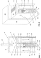
- a first exemplary embodiment of the sealing device or sealing arrangement according to the invention is shown.
- a sealing strip that can be lowered and raised relative to the housing rail 1 is arranged in a housing rail 1.
- the sealing strip has a support rail 2 and a sealing element 3 arranged thereon.
- the housing rail 1 and the carrier rail 2 are preferably made of aluminum, the sealing element 3 preferably consists of a flexible material, such as silicone or rubber.
- the sealing element 3 has two lateral legs 30, which are connected to one another by a lower arch 31. Depending on the embodiment, this arch 31 lies sealingly on a building floor (not shown here) when the sealing strip is lowered. In the embodiment shown here, an inclined lip 32 is formed on the arch 31 so that it rests on the floor when the sealing strip is lowered and can therefore compensate for larger unevenness.
- the fastening ribs 33, 34 are accommodated in corresponding grooves in the support rail 2. Depending on the embodiment, fastening ribs 33, 34 are at the same height.
- the sealing element 3 also called a sealing profile, can also have a different shape. It can be made in one piece or in several parts.
- the sealing strip is held in the housing rail 1 by means of a lowering mechanism, which is not shown in detail here.
- the lowering mechanism usually has a slide 5 ( Figures 4 and 5 ) as well as one or more leaf springs arranged one behind the other and connected to the slide 5, which are tensioned when the sealing strip is lowered by a trigger unit described below and, thanks to their restoring force, raise the sealing strip again.
- the slide 5 is moved in the longitudinal direction by means of an actuation button 50 when closing the door leaf, here the sliding door leaf.
- the housing rail 1 can be fastened in a door groove in different ways. It preferably has a first groove 15 for receiving a fastening bracket 6 ( Figure 3a ) and to accommodate the slider 5.
- a second groove 16 arranged above the first groove 15 forms a space for receiving elements of a trigger unit 7.
- the housing rail 1 is preferably arranged in an outer rail 4.
- the outer rail 4 is preferably also made of aluminum. It can be an independent component for attachment in a groove or on a lower end face of a door leaf T, in particular a sliding door. However, it can also be part of a metal door.
- the housing rail 1 and also the sealing strip of the outer rail 4 arranged therein preferably protrude on at least one end face, preferably on both end faces. This is for example in the Figures 2 and 3b recognizable.
- the mounting bracket is preferably arranged on one side.
- Fastening brackets 6 are preferably present on both end faces.
- An angle element 63 of the mounting bracket 6 preferably engages in the first groove 15 of the housing rail 1.
- the mounting bracket 6 can also be designed differently.
- a base plate 60 of the mounting bracket 6 covers the housing rail 1, so that when the device is mounted, only one cavity A is exposed on the front side thanks to a recess 62 of the mounting bracket 6.
- the base plate 60 is designed to be completely closed and has no recess 62.
- the outer rail 4 is shortened at least on one end face, preferably on both end faces, and the groove of the door leaf is offset accordingly.
- the sealing arrangement according to the invention can be mounted in the door groove in different ways.
- the L-shaped outer rail 4 is preferably inserted into the door groove first and fixed in the door groove base by means of one or more screws 43.
- the remaining lowering seal, ie the housing rail 1 with the sealing strip and the lowering mechanism as well as the trigger unit 7, is then inserted and also screwed on using the front mounting brackets 6.
- the corresponding through opening has the reference number 61.
- the associated screw 90 is in Figure 3b shown.
- the housing rail 1 and the outer rail 4 preferably both have a substantially U-shaped cross section.
- the cross section is preferably constant over the entire length of the rail, with the housing rail 1 preferably having additional recesses in one end region.
- the sealing strip also preferably has a cross-section that remains the same over its entire length.
- the housing rail has two side walls, more precisely an inner side wall 10 and a middle side wall 11, and an upper web 12 connecting these two side walls 10, 11.
- the upper web 12 of the housing rail goes integrally into an upper web 12 the outer rail, which is provided with ventilation openings 14 and which ends at an outer side wall 13, which runs parallel to the inner and middle side walls 10, 11.
- the ventilation openings 14 preferably extend over the entire length of the housing rail 1.
- the three side walls 10, 11, 13 mentioned are preferably of the same height.
- the outer side wall 13 forms part of the outer rail 4.
- the outer rail 4 also has a first side wall 40, a second side wall 41 that is shorter in comparison and an upper web 42 connecting these two side walls 40, 41 to one another.
- the end of the short second side wall 42 rests on the outer side wall 13 and forms a common wall with it.
- a cavity A is formed between the middle side wall 11 and the outer side wall 13, i.e. between the housing rail 1 or the sealing strip 2, 3 and the outer rail 4, which is partially closed at the top by the web 12.
- This cavity A forms the guide channel for triggering the lowering seal and has a connection to the air duct.
- the air duct has an upper part B, which is formed by the cavity between the upper webs 12, 42 of the housing rail 1 or the outer rail, and a side part C, which is formed by the cavity between the first side wall 40 of the outer rail 4 and the inner side wall 10 of the housing rail 1 is formed.
- the air circulation thus takes place from the first lower side of the sealing arrangement through the cavity A to the upper part B and to the side part C to the opposite second lower side of the sealing arrangement. This allows air to be exchanged from one long side of the sealing arrangement to the opposite long side, even when the sealing strip is lowered.
- This airway is in Figure 1 shown with three large arrows. The air flow can be in both directions.
- the trigger unit 7 of the lowering seal In the cavity A and in the area above the first groove 15 there is a part of the trigger unit 7 of the lowering seal can be seen.
- the trigger unit 7 acts on the lowering mechanism, usually on the trigger button connected to the slide or on the slide directly, which automatically lowers the sealing strip 2, 3 mechanically.
- the trigger unit 7 releases the lowering mechanism again, the return springs can relax again and the sealing strip is automatically raised mechanically again.
- the trigger unit acts directly on the sealing strip, which is thereby lowered and raised.
- the sealing strip 2, 3 is shown in the raised state.
- Other types of trigger mechanisms are possible.
- trigger units are used as described in WO 2017/190779 A1 , WO 2017/068173 A1 and WO 2017/191273 A1 are described.
- the trigger unit is most preferred according to WO 2017/191273 A1 with the two interlocking pivot elements 70, 71.
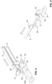
- the Figures 4 and 5 show the trigger unit according to WO'237, which can be used, for example, in the device according to the invention claimed here.
- a first of these pivoting elements 70 which forms a contact element, contacts a stationary contact surface when the door leaf is closed.
- the contact surface is an upwardly directed support surface of a stationary contact module 72 and the contact element rests on this, rotating accordingly during the closing movement of the sliding door.
- the support surface has an inclined surface 720 and an adjoining horizontal surface 721.
- the first pivoting element 70 first moves along the inclined surface 720 until it rests on the horizontal surface 721 when the sliding door is closed.
- the arrows in the Figures 4 and 5 denote the closing direction of the sliding door T.
- the rotational movement is transmitted to a second pivoting element 71, which forms a force transmission element. This presses an actuation button 50 attached to the slide 5.
- a stop 74 here in the form of a pin, is preferably present to limit the pivoting movement of the first pivoting element 70.
- a guide lug 73 is preferably arranged on the stationary contact module 72, which when closing the sliding door the cavity A is inserted.
- This guide nose forms the guide means for guiding the sliding door.
- it is arranged on the same component as the stationary part of the trigger unit. In other embodiments it is a separate component.
- a first part of the trigger unit 7 is preferably held in the sealing arrangement and thus moves in the movable door leaf.
- a second part of the trigger unit 7 is used for activation and is arranged in a stationary manner. In this example it is a preferably upwardly directed support surface 720, 721.
- openings in the front end area of the device so that the corresponding parts of the trigger unit 7 can engage in the area of the housing rail 1 and act on the lowering mechanism. More precisely, there is a lateral through opening 18 in the middle side wall 11 of the housing rail 1 and an upper through opening 17 in the upper web 12, ie in the extension of the web 12 of the housing rail 1. Preferably, at least one opening 19 is also present in the inner side wall 10 of the housing rail 1 in order to store any parts of the trigger unit 7, here for example the second pivoting element 71.
- FIG 6 A variant of the exemplary embodiment described above is shown.
- the lowering seal is designed slightly differently. The remaining parts are the same.
- the arrangement according to the invention can be installed as an independent device in the underside of a door.
- the stationary part of the trigger unit ie the contact module 72 with the inclined surface and the guide lug 73, which is not visible here and which forms the guide means for the sliding door, are screwed to the floor S or to the threshold using screws 75.
- the contact module 72 is also in Figure 7 good to see.
- FIG. 8 and 9 Further exemplary embodiments are shown.
- the basic structure is the same as in the first embodiment.
- a sound-damping element 8 is arranged in the upper part B of the air duct.
- the sound-damping elements 8, 80, 81 are preferably mats or strips made of a sound-absorbing or sound-absorbing material, which are glued to the inside of the outer rail 4 or otherwise connected to it.
- the sealing arrangement according to the invention enables a sliding door to be designed with an air exchange, whereby the sliding door can be made relatively narrow.
Description
Die vorliegende Erfindung betrifft eine Dichtungsanordnung zur Dichtung eines Spalts zwischen einem Türflügel und einem Boden.The present invention relates to a sealing arrangement for sealing a gap between a door leaf and a floor.
Türdichtungen werden in Bereichen eingesetzt, wo ein Schallschutz und ein Schutz vor Zugluft gewünscht sind. Ebenso sollen sie lichtdicht abschliessen. Diese Türdichtungen lassen sich als Bürsten- oder Schleifdichtungen ausbilden. Vorzugsweise sind sie als Absenkdichtungen ausgebildet mit einer Dichtleiste, welche beim Schliessen des Türflügels automatisch abgesenkt wird und welche einen Spalt zwischen Türflügel und Boden dichtet. Bei Flügeltüren erfolgt die Auslösung üblicherweise mechanisch, beispielsweise indem beim Schliessen des Türflügels ein ein- oder zweiseitig vorstehender Betätigungsknopf am Türrahmen eingedrückt wird und dadurch einen federbelasteten Absenkmechanismus aktiviert.Door seals are used in areas where soundproofing and draft protection are desired. They should also be light-tight. These door seals can be designed as brush or grinding seals. They are preferably designed as lowering seals with a sealing strip, which is automatically lowered when the door leaf is closed and which seals a gap between the door leaf and the floor. In the case of hinged doors, activation is usually done mechanically, for example by pressing in an actuation button on the door frame that protrudes on one or two sides when closing the door leaf, thereby activating a spring-loaded lowering mechanism.
In Gebäuden mit einer kontrollierten Lüftung, insbesondere in Niedrigenergiegebäuden und Passivhäusern, muss jedoch auch bei geschlossener Innentüre ein Luftaustausch zwischen den einzelnen Räumen möglich sein. Dies gilt auch für einzelne Räume mit einer Lüftung, wie beispielsweise WC's und Nasszellen wie Badezimmer.However, in buildings with controlled ventilation, especially in low-energy buildings and passive houses, it must be possible to exchange air between the individual rooms even when the interior doors are closed. This also applies to individual rooms with ventilation, such as toilets and wet rooms such as bathrooms.
So offenbart
In
Ferner sind aus dem Stand der Technik Dichtungssysteme für Schiebetüren bekannt, welche ein ungewolltes Öffnen der Schiebetüre durch die Rückstellkraft der abgesenkten Dichtleiste verhindern.
Im Stand der Technik sind zudem schmale Absenkdichtungen für Flügeltüren bekannt. So offenbart
Es ist deshalb eine Aufgabe der Erfindung, eine Dichtungsanordnung zu schaffen, die auch für Schiebetüren, insbesondere für Schiebetüren mit einer Nullkraft-Auslösung der Absenkdichtung, eine Luftzirkulation ermöglicht, die jedoch trotzdem relativ schmal ausgebildet werden kann.It is therefore an object of the invention to create a sealing arrangement which is also suitable for sliding doors, in particular for sliding doors with a zero-force release Lowering seal, which allows air circulation, but can still be made relatively narrow.
Diese Aufgabe löst eine Dichtungsanordnung mit den Merkmalen des Patentanspruchs 1.This task is solved by a sealing arrangement with the features of patent claim 1.
Die erfindungsgemässe Dichtungsanordnung zur Dichtung eines Spalts zwischen einem Türflügel einer Schiebetür und einem Boden weist eine Gehäuseschiene zur Befestigung in oder am Türflügel auf. Die Gehäuseschiene weist eine nach unten offene erste Nut mit einer ersten Seitenwand, einer zweiten Seitenwand und einen diese zwei Seitenwände verbindenden ersten Steg auf. In der ersten Nut ist eine Dichtleiste zur Dichtung des Spalts angeordnet. Die Dichtungsanordnung weist einen nach unten offenen Hohlraum auf, welcher parallel neben der Nut verläuft und welcher einen Führungskanal zur Aufnahme eines Führungsmittels der Schiebetür bildet. Der Hohlraum ist nach oben mindestens teilweise offen ausgebildet. Er ermöglicht dadurch bei gedichtetem Spalt eine Luftzirkulation von einer Seite der Schiebetür über eine Unterseite des Hohlraums zur Oberseite des Hohlraums auf die gegenüberliegende Seite der Schiebertür.The sealing arrangement according to the invention for sealing a gap between a door leaf of a sliding door and a floor has a housing rail for fastening in or on the door leaf. The housing rail has a downwardly open first groove with a first side wall, a second side wall and a first web connecting these two side walls. A sealing strip for sealing the gap is arranged in the first groove. The sealing arrangement has a downwardly open cavity which runs parallel to the groove and which forms a guide channel for receiving a guide means of the sliding door. The cavity is at least partially open at the top. When the gap is sealed, it allows air to circulate from one side of the sliding door via an underside of the cavity to the top of the cavity on the opposite side of the sliding door.
Diese Anordnung ermöglicht es auch für Schiebetüren, im geschlossenen Zustand eine Luftzirkulation zwischen den Räumen zu gewährleisten.This arrangement also makes it possible for sliding doors to ensure air circulation between rooms when closed.
Das Führungsmittel ist üblicherweise ortsfest und vorzugsweise am Boden bzw. auf der Schwelle oder an der Gebäudewand bzw. am seitlichen Türrahmen angeordnet.The guide means is usually stationary and preferably arranged on the floor or on the threshold or on the building wall or on the side door frame.
Da der Führungskanal der Schiebetürführung gleichzeitig für die Luftzirkulation genutzt wird, lassen sich die Dichtungsanordnung und somit auch der Schiebetürflügel sehr schmal ausbilden.Since the guide channel of the sliding door guide is also used for air circulation, the sealing arrangement and thus also the sliding door leaf can be made very narrow.
Diese Anordnung bzw. Vorrichtung eignet sich insbesondere für Schiebetüren, welche zwei Räume innerhalb eines Gebäudes miteinander verbinden, d.h. für Innentüren. Beispielsweise lässt sich eine Innentüre mit einer Türstärke von 38 mm mit einer erfindungsgemässen Dichtungsanordnung von 30.5 mm Breite ausstatten.This arrangement or device is particularly suitable for sliding doors that connect two rooms within a building, i.e. for interior doors. For example, an interior door with a door thickness of 38 mm can be equipped with a sealing arrangement according to the invention that is 30.5 mm wide.
Vorzugsweise weist die Gehäuseschiene eine zweite Nut auf, welche den Hohlraum bildet.The housing rail preferably has a second groove which forms the cavity.
Dies minimiert die Türstärke.This minimizes the door thickness.
Erfindingsgemäß ist auf einer Aussenseite der ersten Seitenwand und auf einer Aussenseite des ersten Stegs ein Luftkanal vorhanden, welcher gemeinsam mit dem Hohlraum die Luftzirkulation ermöglicht. Alternativ verläuft der Luftkanal geradlinig vom ersten Steg nach aussen.According to the invention, an air duct is present on an outside of the first side wall and on an outside of the first web, which enables air circulation together with the cavity. Alternatively, the air duct runs in a straight line from the first web to the outside.
Vorzugsweise ist eine Aussenschiene vorhanden, die beabstandet zur Gehäuseschiene angeordnet ist, wobei der Luftkanal zwischen der Gehäuseschiene und der Aussenschiene verläuft.Preferably, there is an outer rail which is arranged at a distance from the housing rail, with the air duct running between the housing rail and the outer rail.
Der Luftkanal ist dabei vorzugsweise zwischen der Dichtleiste und der Aussenschiene angeordnet und der Hohlraum erstreckt sich in Längsrichtung zwischen der Dichtleiste und der Aussenschiene.The air duct is preferably arranged between the sealing strip and the outer rail and the cavity extends in the longitudinal direction between the sealing strip and the outer rail.
Die seitliche Anordnung des Hohlraums bezieht sich auf den dichtenden Zustand der Dichtleiste, d.h. er befindet sich mindestens teilweise auf gleicher Höhe wie die Dichtleiste in ihrer dichtenden Position.The lateral arrangement of the cavity relates to the sealing state of the sealing strip, i.e. it is at least partially at the same height as the sealing strip in its sealing position.
In bevorzugten Ausführungsformen ist ein Absenkmechanismus zur Anhebung und Absenkung der Dichtleiste relativ zur Gehäuseschiene vorhanden, wobei der Absenkmechanismus mittels einer beim Schliessen des Türflügels aktivierbaren Auslöseeinheit betätigbar ist und wobei die Auslöseeinheit mindestens teilweise im Hohlraum angeordnet ist. Diese Anordnung ermöglicht eine Dreifachnutzung des Hohlraums: für die Führung der Schiebetür, zur Luftzirkulation und für die Betätigung der Absenkdichtung. Diese Dreifachnutzung minimiert den Platzbedarf und ermöglicht so die Bereitstellung einer sehr schmalen Schiebetür.In preferred embodiments, there is a lowering mechanism for raising and lowering the sealing strip relative to the housing rail, the lowering mechanism being actuable by means of a triggering unit that can be activated when the door leaf is closed and the triggering unit being at least partially arranged in the cavity. This arrangement allows the cavity to be used for three purposes: for guiding the sliding door, for air circulation and for operating the lowering seal. This triple use minimizes the space required and thus enables the provision of a very narrow sliding door.
Vorzugsweise sind ein Teil der Auslöseeinheit, vorzugsweise der ortsfeste Teil der Auslöseeinheit, und das Führungsmittel auf einem gemeinsamen Bauteil angeordnet. Vorzugsweise ist das Bauteil ortsfest und am Boden oder auf der Schwelle befestigt. Alternativ zu dieser Lösung ist in anderen bevorzugten Ausführungsformen die Auslöseeinheit an einem anderen Ort angeordnet. Sie kann beispielsweise der Dichtung stirnseitig vorstehen, beispielsweise in der Form eines im Stand der Technik bekannten Auslöseknopfes. In anderen Ausführungsformen ist die Auslöseeinheit mindestens teilweise im Luftkanal angeordnet, also ausserhalb des Hohlraums. Auch dies optimiert den Platzbedarf.Preferably, a part of the trigger unit, preferably the stationary part of the trigger unit, and the guide means are arranged on a common component. The component is preferably stationary and attached to the floor or on the threshold. An alternative to this solution is in other preferred embodiments Trigger unit arranged in a different location. For example, it can protrude from the front of the seal, for example in the form of a release button known in the prior art. In other embodiments, the trigger unit is at least partially arranged in the air duct, i.e. outside the cavity. This also optimizes the space required.
Damit sich die Schiebetür möglichst ohne erhöhten Kraftaufwand schliessen lässt und/oder damit sich die Schiebetür nicht selbsttätig wieder öffnet, ist vorzugsweise eine Nullkraft-Absenkdichtung vorhanden. In bevorzugten Ausführungsformen weist deshalb die Auslöseeinheit ein schwenkbares Kontaktelement und ein Kraftübertragungselement auf, wobei das Kontaktelement beim Schliessen des Türflügels eine Kontaktfläche kontaktiert und sich bei der Schliessbewegung des Türflügels entlang dieser Kontaktfläche bewegt und wobei die Schwenkbewegung des Kontaktelements eine Bewegung des Kraftübertragungselements bewirkt, wodurch ein Absenkmechanismus der Dichtungsanordnung aktiviert und die Dichtleiste abgesenkt wird. Vorzugsweise ist die Kontaktfläche nach oben gerichtet und das Kontaktelement liegt auf der Kontaktfläche auf. Vorzugsweise ist auch das Kraftübertragungselement schwenkbar ausgebildet. Vorzugsweise ist eine der Absenkdichtungen eingesetzt, wie sie in den eingangs erwähnten
Diese erfindungsgemässe Anordnung ist jedoch auch für andere Arten von Auslöseeinheiten, bei welcher die Auslöseeinheit seitlich zur Dichtleiste angeordnet ist, geeignet und vorteilhaft.However, this arrangement according to the invention is also suitable and advantageous for other types of triggering units, in which the triggering unit is arranged laterally to the sealing strip.
Die Aussenschiene und die Gehäuseschiene lassen sich als zwei einzelne Bauteile ausbilden, welche vorzugsweise einzeln am Türflügel befestigt werden. Alternativ ist die Aussenschiene als Teil des Türflügels ausgebildet. Alternativ oder zusätzlich lässt sich die Gehäuseschiene je nach Ausführungsform an der Aussenschiene befestigen. In anderen Ausführungsformen sind die Aussenschiene und die Gehäuseschiene gemeinsam einstückig ausgebildet. Vorzugsweise steht die Gehäuseschiene der Aussenschiene mindestens auf einer Stirnseite, vorzugsweise auf beiden Stirnseiten, vor.The outer rail and the housing rail can be designed as two individual components, which are preferably attached individually to the door leaf. Alternatively, the outer rail is designed as part of the door leaf. Alternatively or additionally, depending on the embodiment, the housing rail can be attached to the outer rail. In other embodiments, the outer rail and the housing rail are formed in one piece. Preferably, the housing rail protrudes from the outer rail at least on one end face, preferably on both end faces.
Erfindungsgemäß ist der Hohlraum von zwei gegenüberliegenden Seitenwänden und einem die zwei Seitenwände miteinander verbindenden oberen Steg begrenzt, wobei der obere Steg und/oder eine der zwei Seitenwände mindestens eine obere Durchgangsöffnung aufweist und wobei diese mindestens eine Durchgangsöffnung die Verbindung vom Hohlraum zum Luftkanal schafft. In dieser Anordnung ist die Gehäuseschiene vorzugsweise über diesen oberen Steg mit der Aussenschiene verbunden und an dieser fixiert. Bevorzugt ist eine erste der zwei Seitenwände eine Seitenwand der Gehäuseschiene und eine zweite der zwei Seitenwände eine Seitenwand der Aussenschiene. Dies vereinfacht die Herstellung und die Montage und minimiert zudem den Platzbedarf.According to the invention, the cavity is made up of two opposite ones Side walls and an upper web connecting the two side walls together, the upper web and / or one of the two side walls having at least one upper through opening and this at least one through opening creating the connection from the cavity to the air duct. In this arrangement, the housing rail is preferably connected to the outer rail via this upper web and fixed to it. Preferably, a first of the two side walls is a side wall of the housing rail and a second of the two side walls is a side wall of the outer rail. This simplifies manufacturing and assembly and also minimizes space requirements.
Vorzugsweise weist die Gehäuseschiene eine dritte Seitenwand auf, wobei die zweite Nut zwischen der zweiten und dritten Seitenwand angeordnet ist. Dies ist eine kostengünstige Ausführung mit einer minimalen Anzahl Bauteile.The housing rail preferably has a third side wall, with the second groove being arranged between the second and third side walls. This is a cost-effective design with a minimal number of components.
In bevorzugten Ausführungsformen ist ein zweiter Steg vorhanden, der die zweite und die dritte Seitenwand miteinander verbindet, wobei der zweite Steg mindestens eine Durchgangsöffnung für die Luftzirkulation aufweist.In preferred embodiments, a second web is present which connects the second and third side walls to one another, the second web having at least one through opening for air circulation.
Vorzugsweise weist der obere Steg des Hohlraums über die Länge der Dichtungsanordnung verteilt mehrere Durchgangsöffnungen auf.Preferably, the upper web of the cavity has a plurality of through openings distributed over the length of the sealing arrangement.
Vorzugsweise fluchten der erste Steg und der zweite Steg miteinander. Vorzugsweise sind der obere Steg der Gehäuseschiene und der obere Steg des Hohlraums gemeinsam einstückig ausgebildet.The first web and the second web are preferably aligned with one another. Preferably, the upper web of the housing rail and the upper web of the cavity are formed together in one piece.
Vorzugsweise weist der zweite Steg über die Länge der Dichtungsanordnung verteilt mehrere Durchgangsöffnungen auf. Dadurch lässt sich über die gesamte Längsrichtung der Dichtungsanordnung und somit des Türflügels ein Luftaustausch ermöglichen. Der Flächenanteil der Durchgangsöffnungen beträgt vorzugsweise annähernd 60% der Fläche des zweiten Stegs.The second web preferably has a plurality of through openings distributed over the length of the sealing arrangement. This makes it possible to exchange air over the entire longitudinal direction of the sealing arrangement and thus of the door leaf. The area share of the through openings is preferably approximately 60% of the area of the second web.
In bevorzugten Ausführungsformen weisen die Gehäuseschiene und die Aussenschiene je einen nach unten offenen, im Wesentlichen u-förmigen Querschnitt auf. Die Luftzirkulation erfolgt vorzugsweise entlang der Aussenseite der Gehäuseschiene von unten durch den u-förmigen Querschnitt der Aussenschiene nach oben und auf der gegenüberliegenden Seite der Gehäuseschiene wieder nach unten bis zum offenen Ende des u-förmigen Querschnitts der Aussenschiene.In preferred embodiments, the housing rail and the outer rail each have a substantially U-shaped cross section that is open at the bottom. The Air circulation preferably takes place along the outside of the housing rail from below through the U-shaped cross section of the outer rail upwards and down again on the opposite side of the housing rail to the open end of the U-shaped cross section of the outer rail.
In bevorzugten Ausführungsformen bestehen die Gehäuseschiene, die Aussenschiene und ein Verbindungselement zwischen Gehäuseschiene und Aussenschiene gemeinsam aus einem ersten und einem zweiten Bauteil, wobei das erste Bauteil einen im Wesentlichen u-förmigen Querschnitt mit einer inneren Mittelwand aufweist und das zweite Bauteil einen im wesentlichen u-förmigen Querschnitt mit einer verkürzten Seitenwand aufweist, wobei die Mittelwand eine Seitenwand der Gehäuseschiene bildet und die verkürzte Seitenwand auf dem ersten Bauteil aufliegt und gemeinsam mit einer Seitenwand des ersten Bauteils eine Seitenwand der Aussenschiene bildet. Das Verbindungselement ist dadurch durch den oberen Steg des Hohlraums gebildet. Je nach Ausführungsform ist das zweite Bauteil ein eigenständiges Bauteil oder es ist ein Teil des Türflügels, insbesondere wenn der Türflügel eine Metalltüre ist.In preferred embodiments, the housing rail, the outer rail and a connecting element between the housing rail and the outer rail consist together of a first and a second component, the first component having a substantially U-shaped cross section with an inner middle wall and the second component having a substantially U-shaped shaped cross section with a shortened side wall, the middle wall forming a side wall of the housing rail and the shortened side wall resting on the first component and, together with a side wall of the first component, forming a side wall of the outer rail. The connecting element is thereby formed by the upper web of the cavity. Depending on the embodiment, the second component is an independent component or it is part of the door leaf, especially if the door leaf is a metal door.
In bevorzugten Ausführungsformen weist eine Seitenwand der Gehäuseschiene und/oder ein oberer Steg der Gehäuseschiene eine Durchgangsöffnung auf, durch welche die Auslöseeinheit auf einen Absenkmechanismus der Dichtleiste wirkt. Dies ist eine platzsparende. Ausbildung.In preferred embodiments, a side wall of the housing rail and/or an upper web of the housing rail has a through opening through which the triggering unit acts on a lowering mechanism of the sealing strip. This is a space saver. Education.
Je nach Ausführungsform ist der Luftkanal leer oder es ist mindestens ein Schalldämpfungselement darin angeordnet.Depending on the embodiment, the air duct is empty or at least one sound-damping element is arranged in it.
Damit die Dichtungsanordnung möglichst schmal ausgebildet ist, empfiehlt sich die Verwendung einer möglichst schmalen Absenkdichtung. In einer bevorzugten Ausführungsform weist die Dichtleiste deshalb eine Trägerschiene und ein daran befestigtes Dichtelement auf, wobei das Dichtelement zwei seitliche Schenkel mit je einer Befestigungsrippe aufweist, wobei die Befestigungsrippen in der Höhe versetzt zueinander auf je einer Seite des Dichtelements angeordnet sind. Vorzugsweise ist eine der Absenkdichtungen eingesetzt, wie sie in den eingangs erwähnten
Weitere Ausführungsformen sind in den abhängigen Ansprüchen angegeben.Further embodiments are specified in the dependent claims.
Bevorzugte Ausführungsformen der Erfindung sind im Folgenden anhand der Zeichnungen beschrieben, die lediglich zur Erläuterung dienen und nicht einschränkend auszulegen sind. In den Zeichnungen zeigen:
- Figur 1
- einen Querschnitt durch eine erfindungsgemässe Dichtungsanordnung in einer ersten Ausführungsform;
Figur 2- eine perspektivische Darstellung der Dichtungsanordnung gemäss
Figur 1 von vorne; - Figur 3a
- eine perspektivische Darstellung der Dichtungsanordnung von einer Seite mit einem Befestigungswinkel;
- Figur 3b
- eine perspektivische Darstellung der Dichtungsanordnung gemäss
Figur 3a von unten und in gedrehter Darstellung, eingebaut in einen Türflügel; Figur 4- eine perspektivische Darstellung eines Teils der Dichtungsanordnung gemäss
Figur 3a mit einer Auslöseeinheit; Figur 5- eine weitere perspektivische Darstellung eines Teils der Dichtungsanordnung gemäss
Figur 4 ; Figur 6- einen Querschnitt durch eine erfindungsgemässe Dichtungsanordnung in einer zweiten Ausführungsform, eingebaut in eine Schiebetür;
Figur 7- eine perspektivische Darstellung der Schiebetür gemäss
Figur 6 ; Figur 8- einen Querschnitt durch eine erfindungsgemässe Dichtungsanordnung in einer zweiten Ausführungsform und
- Figur 9
- einen Querschnitt durch eine erfindungsgemässe Dichtungsanordnung in einer dritten Ausführungsform.
- Figure 1
- a cross section through a sealing arrangement according to the invention in a first embodiment;
- Figure 2
- a perspective view of the sealing arrangement according to
Figure 1 from the front; - Figure 3a
- a perspective view of the sealing arrangement from one side with a mounting bracket;
- Figure 3b
- a perspective view of the sealing arrangement according to
Figure 3a from below and in a rotated view, installed in a door leaf; - Figure 4
- a perspective view of part of the sealing arrangement according to
Figure 3a with a trigger unit; - Figure 5
- a further perspective view of part of the sealing arrangement according to
Figure 4 ; - Figure 6
- a cross section through a sealing arrangement according to the invention in a second embodiment, installed in a sliding door;
- Figure 7
- a perspective view of the sliding door according to
Figure 6 ; - Figure 8
- a cross section through a sealing arrangement according to the invention in a second embodiment and
- Figure 9
- a cross section through a sealing arrangement according to the invention in a third embodiment.
In den
Das Dichtelement 3 weist zwei seitliche Schenkel 30 auf, welche durch einen unteren Bogen 31 miteinander verbunden sind. Je nach Ausführungsform liegt dieser Bogen 31 bei abgesenkter Dichtleiste dichtend auf einem hier nicht dargestellten Gebäudeboden auf. In der hier dargestellten Ausführungsform ist am Bogen 31 eine Schräglippe 32 angeformt, so dass diese bei abgesenkter Dichtleiste auf dem Boden aufliegt und dadurch auch grössere Unebenheiten ausgleichen kann. Auf der Innenseite jedes Schenkels 30 ist je eine Befestigungsrippe 33, 34 angeordnet. Die Befestigungsrippen 33, 34 sind in entsprechende Nuten der Trägerschiene 2 aufgenommen. Je nach Ausführungsform befinden sich Befestigungsrippen 33, 34 auf gleicher Höhe. In dem hier dargestellten Beispiel sind sie jedoch in der Höhe versetzt zueinander angeordnet und greifen vorzugsweise über die Mittelachse M der Trägerschiene 2 in die Nuten ein. Die untere Befestigungsrippe 33 ist entsprechend in der Höhe beabstandet zur oberen Befestigungsrippe 34 angeordnet. Dadurch lässt sich die Dichtleiste und somit die Absenkdichtung sehr schmal ausbilden. Das Dichtelement 3, auch Dichtungsprofil genannt, kann auch eine andere Form aufweisen. Es kann einstückig oder mehrteilig ausgebildet sein.The sealing
Die Dichtleiste ist mittels eines hier nicht im Detail dargestellten Absenkmechanismus in der Gehäuseschiene 1 gehalten. Üblicherweise weist der Absenkmechanismus einen sich in Längsrichtung der Absenkdichtung erstreckenden Schieber 5 (
Die Gehäuseschiene 1 lässt sich auf unterschiedliche Weise in einer Türnut befestigen. Vorzugsweise weist sie eine erste Nut 15 zur Aufnahme eines Befestigungswinkels 6 (
Die Gehäuseschiene 1 ist vorzugsweise in einer Aussenschiene 4 angeordnet. Die Aussenschiene 4 ist vorzugsweise ebenfalls aus Aluminium gefertigt. Sie kann ein eigenständiges Bauteil zur Befestigung in einer Nut oder an einer unteren Stirnseite eines Türflügels T, insbesondere einer Schiebetür, sein. Sie kann jedoch auch Teil einer Metalltüre sein. Vorzugsweise steht die Gehäuseschiene 1 und auch die darin angeordnete Dichtleiste der Aussenschiene 4 auf mindestens einer Stirnseite, vorzugsweise auf beiden Stirnseiten, vor. Dies ist beispielsweise in den
In den
Die Aussenschiene 4 ist in diesem Beispiel mindestens auf einer Stirnseite, vorzugsweise auf beiden Stirnseiten, verkürzt und die Nut des Türflügels ist entsprechend abgesetzt.In this example, the
Die erfindungsgemässe Dichtungsanordnung lässt sich auf unterschiedliche Weise in der Türnut montieren. Im hier dargestellten Beispiel wird die L-förmige Aussenschiene 4 vorzugsweise als erstes in die Türnut eingebracht und mittels einer oder mehreren Schrauben 43 im Türnutgrund fixiert. Anschliessend wird die restliche Absenkdichtung, d.h. die Gehäuseschiene 1 mit der Dichtleiste und dem Absenkmechanismus sowie die Auslöseeinheit 7, eingebracht und mittels der stirnseitigen Befestigungswinkel 6 ebenfalls angeschraubt. Die entsprechende Durchgangsöffnung weist das Bezugszeichen 61 auf. Die zugehörige Schraube 90 ist in
Die Gehäuseschiene 1 und die Aussenschiene 4 weisen vorzugsweise beide einen im Wesentlichen u-förmigen Querschnitt auf. Der Querschnitt ist vorzugsweise über die gesamte Länge der Schiene gleichbleibend, wobei die Gehäuseschiene 1 in einem Endbereich vorzugsweise zusätzliche Ausnehmungen aufweist. Auch die Dichtleiste weist vorzugsweise einen über ihre gesamte Länge gleichbleibenden Querschnitt auf.The housing rail 1 and the
Die Gehäuseschiene weist zwei Seitenwände, genauer eine innere Seitenwand 10 und eine mittlere Seitenwand 11, und einen diese zwei Seitenwände 10, 11 verbindenden oberen Steg 12 auf. Der obere Steg 12 der Gehäuseschiene geht einstückig in einen oberen Steg 12 der Aussenschiene über, welcher mit Lüftungsöffnungen 14 versehen ist und welcher an einer äusseren Seitenwand 13 endet, die parallel zur inneren und zur mittleren Seitenwand 10, 11 verläuft. Die Lüftungsöffnungen 14 erstrecken sich vorzugsweise über die gesamte Länge der Gehäuseschiene 1.The housing rail has two side walls, more precisely an
Die genannten drei Seitenwände 10, 11, 13 sind vorzugsweise gleich hoch ausgebildet. Die äussere Seitenwand 13 bildet einen Teil der Aussenschiene 4. Die Aussenschiene 4 weist ferner eine erste Seitenwand 40, eine im Vergleich dazu kürzere zweite Seitenwand 41 und einen diese zwei Seitenwände 40, 41 miteinander verbindenden oberen Steg 42 auf. Die kurze zweite Seitenwand 42 liegt mit ihrem Ende auf der äusseren Seitenwand 13 auf und bildet mit dieser eine gemeinsame Wand. Wie in den
Die in den
Im Hohlraum A und im Bereich oberhalb der ersten Nut 15 ist ein Teil der Auslöseeinheit 7 der Absenkdichtung erkennbar. Die Auslöseeinheit 7 wirkt beim Schliessen des Türflügels auf den Absenkmechanismus, üblicherweise auf dem mit dem Schieber verbundenen Auslöseknopf oder auf den Schieber direkt, welcher die Dichtleiste 2, 3 somit automatisch mechanisch absenkt. Beim Öffnen des Türflügels gibt die Auslöseeinheit 7 den Absenkmechanismus wieder frei, die Rückstellfedern können sich wieder entspannen und die Dichtleiste wird wieder automatisch mechanisch angehoben. In anderen Ausführungsformen wirkt die Auslöseeinheit direkt auf die Dichtleiste, welche dadurch absenkt und angehoben wird. In allen hier wiedergegebenen Figuren ist die Dichtleiste 2, 3 im angehobenen Zustand dargestellt. Weitere Arten von Auslösemechanismen sind möglich.In the cavity A and in the area above the
In bevorzugten Ausführungsformen werden Auslöseeinheit verwendet, wie sie in
Im hier dargestellten Beispiel weist die Auflagefläche eine Schrägfläche 720 und eine daran anschliessende Horizontalfläche 721 auf. Beim Schliessen des Türflügels T bewegt sich das erste Schwenkelement 70 zuerst entlang der Schrägfläche 720 bis es bei geschlossener Schiebetür auf der Horizontalfläche 721 aufliegt. Die Pfeile in den
Ein erster Teil der Auslöseeinheit 7 ist vorzugsweise in der Dichtungsanordnung gehalten und bewegt sich somit im bewegbaren Türflügel mit. Ein zweiter Teil der Auslöseeinheit 7 dient der Aktivierung und ist ortsfest angeordnet. In diesem Beispiel ist es eine vorzugsweise nach oben gerichtete Auflagefläche 720, 721.A first part of the
Wie in
In
In den
Die erfindungsgemässe Dichtungsanordnung ermöglicht eine Ausbildung einer Schiebetüre mit einem Luftaustausch, wobei die Schiebetür relativ schmal ausgebildet werden kann.The sealing arrangement according to the invention enables a sliding door to be designed with an air exchange, whereby the sliding door can be made relatively narrow.
Claims (13)
- Seal arrangement for sealing a gap between a door leaf of a sliding door and a floor,wherein the seal arrangement has a housing rail (1) for fastening in or on the door leaf, wherein the housing rail (1) has a downwardly open first groove with a first side wall (10), a second side wall (11) and a first web (12) connecting these two side walls (10, 11), and wherein a sealing strip (2, 3) for sealing the gap is arranged in the first groove,wherein the seal arrangement has a downwardly open cavity (A) which runs parallel next to the groove and which forms a guide channel for receiving a guide means of the sliding door, wherein the cavity (A) is designed to be at least partially open upwards and thus, when the gap is sealed, allows air circulation from one side of the sliding door to the opposite side of the sliding door via a lower side of the cavity (A) to the upper side of the cavity (A), wherein an air channel is present which, together with the cavity (A), allows the air circulation, wherein the air channel (B, C) is present on an outer side of the first side wall (10) and on an outer side of the first web (12), or wherein it runs rectilinearly outwards from the first web (12),characterizedin that the cavity (A) is delimited by two opposite side walls (11, 13) and an upper web interconnecting the two side walls (11, 13), wherein the upper web and/or one of the two side walls (11, 13) have/has at least one upper through-opening (14, 17), wherein the at least one through-opening (14, 17) provides a connection from the cavity (A) to the air channel.
- Seal arrangement according to Claim 1, wherein it has an outer rail (4) which is arranged spaced apart from the housing rail (1), wherein the air channel (B, C) runs between the housing rail (1) and the outer rail (4).
- Seal arrangement according to either of Claims 1 and 2, wherein a lowering mechanism for raising and lowering the sealing strip (2, 3) relative to the housing rail (1) is present, wherein the lowering mechanism can be actuated by means of a triggering unit (7) which can be activated upon closing of the door leaf, and wherein the triggering unit (7) is at least partially arranged in the cavity (A).
- Seal arrangement according to either of Claims 1 and 2, wherein a lowering mechanism for raising and lowering the sealing strip (2, 3) relative to the housing rail (1) is present, wherein the lowering mechanism can be actuated by means of a triggering unit (7) which can be activated upon closing of the door leaf, and wherein the triggering unit (7) is at least partially arranged in the air channel (B, C).
- Seal arrangement according to either of Claims 3 and 4, wherein the triggering unit (7) has a pivotable contact element (70) and a force transmission element (71), wherein, upon closing the door leaf (T), the contact element (70) makes contact with a contact surface (720, 721) and moves along this contact surface (720, 721) during the closing movement of the door leaf (T), and wherein the pivoting movement of the contact element (70) brings about a movement of the force transmission element (71), as a result of which a lowering mechanism (5) of the seal arrangement is activated and the sealing strip (2, 3) is lowered.
- Seal arrangement according to one of Claims 3 to 5, wherein the second side wall (11) of the housing rail (1) and/or the first web (12) of the housing rail (1) have/has a through-opening (17, 18) through which the triggering unit (7) acts on a lowering mechanism (5) of the sealing strip (2, 3).
- Seal arrangement according to one of Claims 1 to 6, wherein the housing rail (1) has a second groove, which forms the cavity (A).
- Seal arrangement according to Claim 7, wherein the housing rail (1) has a third side wall (13), and wherein the second groove is arranged between the second and third side wall (11, 13).
- Seal arrangement according to Claim 8, wherein the upper web interconnects the second and the third side wall (11, 13).
- Seal arrangement according to Claim 8, wherein the upper web of the cavity (A) has a plurality of through-openings (14) distributed over the length of the seal arrangement.
- Seal arrangement according to either of Claims 9 and 10, wherein the first web (12) and the upper web are aligned with one another.
- Seal arrangement according to one of Claims 9 to 11, wherein the first web (12) of the housing rail (1) and the upper web of the cavity (A) are formed together in one piece.
- Seal arrangement according to one of Claims 2 to 12, wherein the housing rail (1) projects from the outer rail (4) at least on an end side.
Priority Applications (1)
| Application Number | Priority Date | Filing Date | Title |
|---|---|---|---|
| EP19187846.1A EP3770370B1 (en) | 2019-07-23 | 2019-07-23 | Door seal arrangement |
Applications Claiming Priority (1)
| Application Number | Priority Date | Filing Date | Title |
|---|---|---|---|
| EP19187846.1A EP3770370B1 (en) | 2019-07-23 | 2019-07-23 | Door seal arrangement |
Publications (2)
| Publication Number | Publication Date |
|---|---|
| EP3770370A1 EP3770370A1 (en) | 2021-01-27 |
| EP3770370B1 true EP3770370B1 (en) | 2024-01-17 |
Family
ID=67438557
Family Applications (1)
| Application Number | Title | Priority Date | Filing Date |
|---|---|---|---|
| EP19187846.1A Active EP3770370B1 (en) | 2019-07-23 | 2019-07-23 | Door seal arrangement |
Country Status (1)
| Country | Link |
|---|---|
| EP (1) | EP3770370B1 (en) |
Citations (3)
| Publication number | Priority date | Publication date | Assignee | Title |
|---|---|---|---|---|
| EP1936097A1 (en) * | 2006-12-19 | 2008-06-25 | Planet GDZ AG | Door sealant system |
| WO2010142053A1 (en) * | 2009-06-09 | 2010-12-16 | Planet Gdz Ag | Door sealing system |
| EP2824271A1 (en) * | 2013-07-08 | 2015-01-14 | Planet GDZ AG | Door sealant system |
Family Cites Families (5)
| Publication number | Priority date | Publication date | Assignee | Title |
|---|---|---|---|---|
| CH705344A1 (en) | 2011-08-02 | 2013-02-15 | Planet Gdz Ag | Seal for a barrier-free door. |
| EP2664741A1 (en) * | 2012-05-18 | 2013-11-20 | Planet GDZ AG | Door sealant system |
| DE102015118174A1 (en) | 2015-10-23 | 2017-04-27 | Huga Hubert Gaisendrees KG | Sealing device for a sliding door and sliding door provided therewith |
| SG11201809061PA (en) | 2016-05-04 | 2018-11-29 | Planet Gdz Ag | Sealing device for a sliding door |
| SG11201809062YA (en) | 2016-05-04 | 2018-11-29 | Planet Gdz Ag | Sealing device |
-
2019
- 2019-07-23 EP EP19187846.1A patent/EP3770370B1/en active Active
Patent Citations (3)
| Publication number | Priority date | Publication date | Assignee | Title |
|---|---|---|---|---|
| EP1936097A1 (en) * | 2006-12-19 | 2008-06-25 | Planet GDZ AG | Door sealant system |
| WO2010142053A1 (en) * | 2009-06-09 | 2010-12-16 | Planet Gdz Ag | Door sealing system |
| EP2824271A1 (en) * | 2013-07-08 | 2015-01-14 | Planet GDZ AG | Door sealant system |
Also Published As
| Publication number | Publication date |
|---|---|
| EP3770370A1 (en) | 2021-01-27 |
Similar Documents
| Publication | Publication Date | Title |
|---|---|---|
| EP3452680B1 (en) | Sealing device | |
| EP0085173B1 (en) | Ventilation device | |
| EP1936097B1 (en) | Door sealant system | |
| EP3225771B1 (en) | Threshold for a sliding door and sliding door | |
| DE202009014785U1 (en) | sliding door | |
| EP2400099B1 (en) | Thermally insulating leaf assembly | |
| EP3165701A1 (en) | Ventilation element for window with flap acting as chicane | |
| EP2876243B1 (en) | Sliding gate with integrated door leaf | |
| EP3768931B1 (en) | Sealing unit | |
| EP3770370B1 (en) | Door seal arrangement | |
| EP1498569B1 (en) | Door seal | |
| DE10157805A1 (en) | Sliding and swiveling door leaf element | |
| EP0784144A1 (en) | Magnetic door seal and associated profiles for its manufacture | |
| EP0011336B1 (en) | Sealing for a door without a sill and with a revolving wing | |
| EP2381056B1 (en) | Floor guide for a side sectional door | |
| EP3524765A1 (en) | Anti-burglary device that can be lowered | |
| AT512327A1 (en) | LIFTING / SLIDING | |
| EP3019684B1 (en) | Door sealing system | |
| EP2088277B1 (en) | Seal assembly for a door without a threshold | |
| EP1005621A1 (en) | Ventilator for window elements | |
| EP0047880A1 (en) | Sliding shutter ventilation device | |
| EP1279791A1 (en) | Drop door seal | |
| EP1762691B1 (en) | Seal for a door or window corner | |
| EP3085876A1 (en) | Drop-down seal device and trip unit | |
| EP3985219A1 (en) | Arrangement with a floor seal for a door, in which an intermediate space is provided between a door leaf and a frame accommodating the sole axis of rotation of the door leaf |
Legal Events
| Date | Code | Title | Description |
|---|---|---|---|
| PUAI | Public reference made under article 153(3) epc to a published international application that has entered the european phase |
Free format text: ORIGINAL CODE: 0009012 |
|
| STAA | Information on the status of an ep patent application or granted ep patent |
Free format text: STATUS: THE APPLICATION HAS BEEN PUBLISHED |
|
| AK | Designated contracting states |
Kind code of ref document: A1 Designated state(s): AL AT BE BG CH CY CZ DE DK EE ES FI FR GB GR HR HU IE IS IT LI LT LU LV MC MK MT NL NO PL PT RO RS SE SI SK SM TR |
|
| AX | Request for extension of the european patent |
Extension state: BA ME |
|
| STAA | Information on the status of an ep patent application or granted ep patent |
Free format text: STATUS: REQUEST FOR EXAMINATION WAS MADE |
|
| 17P | Request for examination filed |
Effective date: 20210629 |
|
| RBV | Designated contracting states (corrected) |
Designated state(s): AL AT BE BG CH CY CZ DE DK EE ES FI FR GB GR HR HU IE IS IT LI LT LU LV MC MK MT NL NO PL PT RO RS SE SI SK SM TR |
|
| STAA | Information on the status of an ep patent application or granted ep patent |
Free format text: STATUS: EXAMINATION IS IN PROGRESS |
|
| 17Q | First examination report despatched |
Effective date: 20221031 |
|
| GRAP | Despatch of communication of intention to grant a patent |
Free format text: ORIGINAL CODE: EPIDOSNIGR1 |
|
| STAA | Information on the status of an ep patent application or granted ep patent |
Free format text: STATUS: GRANT OF PATENT IS INTENDED |
|
| INTG | Intention to grant announced |
Effective date: 20230814 |
|
| GRAS | Grant fee paid |
Free format text: ORIGINAL CODE: EPIDOSNIGR3 |
|
| GRAA | (expected) grant |
Free format text: ORIGINAL CODE: 0009210 |
|
| STAA | Information on the status of an ep patent application or granted ep patent |
Free format text: STATUS: THE PATENT HAS BEEN GRANTED |
|
| AK | Designated contracting states |
Kind code of ref document: B1 Designated state(s): AL AT BE BG CH CY CZ DE DK EE ES FI FR GB GR HR HU IE IS IT LI LT LU LV MC MK MT NL NO PL PT RO RS SE SI SK SM TR |
|
| REG | Reference to a national code |
Ref country code: GB Ref legal event code: FG4D Free format text: NOT ENGLISH |
|
| REG | Reference to a national code |
Ref country code: DE Ref legal event code: R096 Ref document number: 502019010396 Country of ref document: DE |
|
| REG | Reference to a national code |
Ref country code: CH Ref legal event code: EP |
|
| REG | Reference to a national code |
Ref country code: IE Ref legal event code: FG4D Free format text: LANGUAGE OF EP DOCUMENT: GERMAN |
|
| REG | Reference to a national code |
Ref country code: NL Ref legal event code: FP |