EP1933154A2 - Analyseur - Google Patents
Analyseur Download PDFInfo
- Publication number
- EP1933154A2 EP1933154A2 EP08006055A EP08006055A EP1933154A2 EP 1933154 A2 EP1933154 A2 EP 1933154A2 EP 08006055 A EP08006055 A EP 08006055A EP 08006055 A EP08006055 A EP 08006055A EP 1933154 A2 EP1933154 A2 EP 1933154A2
- Authority
- EP
- European Patent Office
- Prior art keywords
- motor
- aspirating
- aspirating pipette
- pipette
- sample
- Prior art date
- Legal status (The legal status is an assumption and is not a legal conclusion. Google has not performed a legal analysis and makes no representation as to the accuracy of the status listed.)
- Granted
Links
- 239000007788 liquid Substances 0.000 claims abstract description 116
- 230000001360 synchronised effect Effects 0.000 claims description 3
- 239000008280 blood Substances 0.000 description 11
- 210000004369 blood Anatomy 0.000 description 11
- 238000000034 method Methods 0.000 description 6
- 230000001174 ascending effect Effects 0.000 description 4
- 239000003153 chemical reaction reagent Substances 0.000 description 4
- 230000003287 optical effect Effects 0.000 description 3
- 229910001220 stainless steel Inorganic materials 0.000 description 3
- 239000010935 stainless steel Substances 0.000 description 3
- 238000010586 diagram Methods 0.000 description 2
- 239000004973 liquid crystal related substance Substances 0.000 description 2
- 238000001514 detection method Methods 0.000 description 1
- 239000012530 fluid Substances 0.000 description 1
- 238000005259 measurement Methods 0.000 description 1
- 230000000149 penetrating effect Effects 0.000 description 1
- 238000007789 sealing Methods 0.000 description 1
Images


Classifications
-
- G—PHYSICS
- G01—MEASURING; TESTING
- G01N—INVESTIGATING OR ANALYSING MATERIALS BY DETERMINING THEIR CHEMICAL OR PHYSICAL PROPERTIES
- G01N35/00—Automatic analysis not limited to methods or materials provided for in any single one of groups G01N1/00 - G01N33/00; Handling materials therefor
- G01N35/10—Devices for transferring samples or any liquids to, in, or from, the analysis apparatus, e.g. suction devices, injection devices
- G01N35/1009—Characterised by arrangements for controlling the aspiration or dispense of liquids
- G01N35/1016—Control of the volume dispensed or introduced
-
- G—PHYSICS
- G01—MEASURING; TESTING
- G01N—INVESTIGATING OR ANALYSING MATERIALS BY DETERMINING THEIR CHEMICAL OR PHYSICAL PROPERTIES
- G01N35/00—Automatic analysis not limited to methods or materials provided for in any single one of groups G01N1/00 - G01N33/00; Handling materials therefor
- G01N35/10—Devices for transferring samples or any liquids to, in, or from, the analysis apparatus, e.g. suction devices, injection devices
- G01N35/1009—Characterised by arrangements for controlling the aspiration or dispense of liquids
- G01N35/1011—Control of the position or alignment of the transfer device
-
- G—PHYSICS
- G01—MEASURING; TESTING
- G01N—INVESTIGATING OR ANALYSING MATERIALS BY DETERMINING THEIR CHEMICAL OR PHYSICAL PROPERTIES
- G01N35/00—Automatic analysis not limited to methods or materials provided for in any single one of groups G01N1/00 - G01N33/00; Handling materials therefor
- G01N35/10—Devices for transferring samples or any liquids to, in, or from, the analysis apparatus, e.g. suction devices, injection devices
- G01N35/1079—Devices for transferring samples or any liquids to, in, or from, the analysis apparatus, e.g. suction devices, injection devices with means for piercing stoppers or septums
-
- B—PERFORMING OPERATIONS; TRANSPORTING
- B01—PHYSICAL OR CHEMICAL PROCESSES OR APPARATUS IN GENERAL
- B01L—CHEMICAL OR PHYSICAL LABORATORY APPARATUS FOR GENERAL USE
- B01L3/00—Containers or dishes for laboratory use, e.g. laboratory glassware; Droppers
- B01L3/02—Burettes; Pipettes
- B01L3/021—Pipettes, i.e. with only one conduit for withdrawing and redistributing liquids
-
- G—PHYSICS
- G01—MEASURING; TESTING
- G01N—INVESTIGATING OR ANALYSING MATERIALS BY DETERMINING THEIR CHEMICAL OR PHYSICAL PROPERTIES
- G01N35/00—Automatic analysis not limited to methods or materials provided for in any single one of groups G01N1/00 - G01N33/00; Handling materials therefor
- G01N35/02—Automatic analysis not limited to methods or materials provided for in any single one of groups G01N1/00 - G01N33/00; Handling materials therefor using a plurality of sample containers moved by a conveyor system past one or more treatment or analysis stations
- G01N35/04—Details of the conveyor system
- G01N2035/0474—Details of actuating means for conveyors or pipettes
- G01N2035/0475—Details of actuating means for conveyors or pipettes electric, e.g. stepper motor, solenoid
-
- G—PHYSICS
- G01—MEASURING; TESTING
- G01N—INVESTIGATING OR ANALYSING MATERIALS BY DETERMINING THEIR CHEMICAL OR PHYSICAL PROPERTIES
- G01N35/00—Automatic analysis not limited to methods or materials provided for in any single one of groups G01N1/00 - G01N33/00; Handling materials therefor
- G01N35/02—Automatic analysis not limited to methods or materials provided for in any single one of groups G01N1/00 - G01N33/00; Handling materials therefor using a plurality of sample containers moved by a conveyor system past one or more treatment or analysis stations
- G01N35/04—Details of the conveyor system
- G01N2035/0474—Details of actuating means for conveyors or pipettes
- G01N2035/0491—Position sensing, encoding; closed-loop control
-
- G—PHYSICS
- G01—MEASURING; TESTING
- G01N—INVESTIGATING OR ANALYSING MATERIALS BY DETERMINING THEIR CHEMICAL OR PHYSICAL PROPERTIES
- G01N35/00—Automatic analysis not limited to methods or materials provided for in any single one of groups G01N1/00 - G01N33/00; Handling materials therefor
- G01N35/10—Devices for transferring samples or any liquids to, in, or from, the analysis apparatus, e.g. suction devices, injection devices
- G01N2035/1027—General features of the devices
- G01N2035/1034—Transferring microquantities of liquid
- G01N2035/1039—Micropipettes, e.g. microcapillary tubes
-
- Y—GENERAL TAGGING OF NEW TECHNOLOGICAL DEVELOPMENTS; GENERAL TAGGING OF CROSS-SECTIONAL TECHNOLOGIES SPANNING OVER SEVERAL SECTIONS OF THE IPC; TECHNICAL SUBJECTS COVERED BY FORMER USPC CROSS-REFERENCE ART COLLECTIONS [XRACs] AND DIGESTS
- Y10—TECHNICAL SUBJECTS COVERED BY FORMER USPC
- Y10T—TECHNICAL SUBJECTS COVERED BY FORMER US CLASSIFICATION
- Y10T436/00—Chemistry: analytical and immunological testing
- Y10T436/25—Chemistry: analytical and immunological testing including sample preparation
- Y10T436/2575—Volumetric liquid transfer
Definitions
- the present invention relates to a liquid aspirator and an analyzer provided with the same and, more particularly, to a liquid aspirator, in which liquid can be aspirated from a container containing therein liquid in a fine quantity.
- First liquid aspirator embodying feature of the present invention can aspirate liquid in a fine quantity contained in a liquid container by securing the contact of the tip of an aspirating pipette with the bottom of the container with a remarkably simple configuration.
- Second liquid aspirator embodying feature of the present invention includes an aspirating pipette; a drive source for descending the aspirating pipette; and a controller for controlling the drive source; the aspirating pipette being stopped from being descended by loss of synchronism of the drive source caused by upward force to be exerted on the aspirating pipette.
- Third liquid aspirator embodying feature of the present invention includes an aspirating pipette; a motor for descending the aspirating pipette; a motor drive unit for supplying a motor drive current to the motor; and a controller for controlling the motor drive unit in such a manner that the motor drive current to be supplied to the motor by the motor drive unit becomes small until the aspirating pipette is brought into contact with the bottom of the liquid container disposed under the aspirating pipette after the start of the descendent movement of the aspirating pipette.
- Fourth liquid aspirator embodying feature of the present invention includes an aspirating pipette; a drive source for descending the aspirating pipette; and a controller for instructing the drive source to descend the aspirating pipette by a distance greater than a distance between the bottom of the liquid container disposed under the aspirating pipette and the tip of the aspirating pipette; the aspirating pipette descending according to the drive of the drive source while being stopped from being descended with the application of reactive force from the liquid container in contact with the bottom of the liquid container.
- Fifth liquid aspirator embodying feature of the present invention includes an aspirating pipette; a drive source for descending the aspirating pipette; and a controller for controlling the drive source in such a manner as to descend the aspirating pipette so as to bring the aspirating pipette into contact with the bottom of the liquid container disposed under the aspirating pipette; the synchronization of the drive source being lost by bringing the aspirating pipette into contact with the bottom of the liquid container.
- First Analyzer embodying feature of the present invention can be operated in a first mode in which liquid is aspirated from an open container through a first aspirating pipette for aspirating the liquid from the open container and in a second mode in which liquid is aspirated from a closed container through a second aspirating pipette for aspirating the liquid from the closed container.
- Second analyzer embodying feature of the present invention includes an aspirating pipette holding member capable of selectively holding the first aspirating pipette and the second aspirating pipette; a drive source for descending the aspirating pipette holding member; and a controller for varying a descending process of the aspirating pipette holding member between the first mode and the second mode.
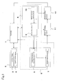
- FIG. 1 is a block diagram illustrating the configuration of a blood analyzer in a preferred embodiment according to the present invention.
- a controller 1 includes a CPU, a ROM, a RAM, an I/O port and the like.
- the controller 1 actuates a drive circuit unit 8 upon receipt of outputs from a touch panel 3 in an input/output unit 2 and an aspirating pipette ascender/descender 6 in a liquid aspirator 5.
- the liquid aspirator 5 includes the aspirating pipette ascender/descender 6, a sample aspirating pump 7 and the drive circuit unit 8.
- the drive circuit unit 8 is adapted to drive the aspirating pipette ascender/descender 6, the sample aspirating pump 7, an analyzing sample preparer 11 and an analyzing data detector 12.
- the controller 1 performs an analysis upon receipt of detection data from the analyzing data detector 12, and then, outputs the analysis result to a liquid crystal display 4 in the input/output unit 2.
- FIG. 2 is a front view showing the aspirating pipette ascender/descender 6.
- the aspirating pipette ascender/descender 6 includes a base table 13, a support plate 15 erected on the base table 13, an elongated horizontal arm 21 extending in a horizontal direction with respect to the support plate 15, a screw shaft 22 penetrating the horizontal arm 21 in a vertical direction and being rotatably supported by the support plate 15, a nut 23 engaging with the screw shaft 22 via a screw and being fixed to the horizontal arm 21, a slide rail 24a disposed in the support plate 15 in parallel to the screw shaft 22, a sliding member 24b disposed at the left end of the horizontal arm 21 so as to guide the horizontal arm 21 in a vertical direction in slidable engagement with the slide rail 24a, and a stepping motor 25 serving as a part of an aspirating pipette ascending/descending drive source secured to the support plate 15.
- Pulleys 26 and 27 are fixed to the upper end of the screw shaft 22 and an output shaft of the motor 25, respectively.
- a timing belt 28 is stretched across the pulleys 26 and 27. Therefore, the horizontal arm 21 can be vertically moved up and down according to the drive of the stepping motor 25.
- an aspirating pipette holding tool 16 which holds an aspirating pipette PT in a vertical direction in a replaceable (i.e., detachable) manner.
- the base end of the aspirating pipette PT is detachably connected to a flexible tube 17, and further, is connected to the sample aspirating pump 7 (see FIG. 1 ) via the flexible tube 17.
- a rack 14 is mounted on the base table 13.
- a sample container SP for containing a liquid sample (e.g., blood) therein.
- the rack 14 and the sample container SP are inelastically supported by the base table 13 and the rack 14, respectively.
- an aspirating pipette position detecting sensor 29 for detecting whether or not the horizontal arm 21 reaches an uppermost initial position.
- the stepping motor 25 for ascending/descending the aspirating pipette is driven upon receipt of a drive pulse (i.e., a pulse current) as a motor driving current applied from a stepping motor drive circuit 9 (see FIG. 1 ) at each phase. Furthermore, in the case where rotating torque (i.e., drive force) need to be varied, a motor driving current (i.e., the magnitude of the drive pulse) is varied (or adjusted) by a motor current varying circuit (i.e., a drive force varying unit) 10 in accordance with an instruction issued from the controller 1.
- a drive pulse i.e., a pulse current
- a motor driving current i.e., the magnitude of the drive pulse
- the motor drive circuit 9 As the motor drive circuit 9 is used a commercially available IC such as SLA7032M (manufactured by SANKEN ELECTRIC CO., LTD.); in the meantime, as the motor current varying circuit 10 is used a gate circuit for setting a drive current in the motor drive circuit 9.
- SLA7032M manufactured by SANKEN ELECTRIC CO., LTD.
- the motor current varying circuit 10 is used a gate circuit for setting a drive current in the motor drive circuit 9.
- the stepping motor 25 is driven by the drive pulse.
- the ascending/descending speed of the aspirating pipette PT depends upon the frequency of the drive pulse; in the meantime, an ascendent/descendent distance depends upon the total number of drive pulses to be supplied to the stepping motor 25.
- the output torque (i.e., the drive force) of the motor is determined by the motor driving current (i.e., the magnitude of the drive pulse).
- the motor loses its synchronization at a load of the output torque or higher of the motor. The loss of synchronization signifies a state in which the rotation of the stepping motor cannot be synchronized with the supplied drive pulse.
- the blood analyzer illustrated in FIG. 1 is designed to be operated in two modes: in an open mode (i.e., a first mode) and a closed mode (i.e., a second mode).
- the open mode is a mode in which a container having an open upper portion (i.e., an open container) is used as the sample container SP;
- the closed mode is a mode in which a container having an upper portion closed by a rubber cap or the like is used as the sample container SP.
- the aspirating pipettes PT having tip ends different in shape are used in the open mode and in the closed mode.
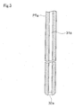
- FIG. 3 is a cross-sectional view showing an aspirating pipette PTa for use in the open mode
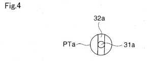
- FIG. 4 is a plan view showing the tip of the aspirating pipette PTa.
- the aspirating pipette PTa is preferably used for aspirating all of a sample from an open type sample container which contains a fine quantity of sample therein.
- the aspirating pipette PTa is formed of a pipe made of stainless steel having an outer diameter of 1.5 mm, and includes a coaxial aspirating channel 31a having an inner diameter of 0.6 mm.
- the tip of the aspirating pipette PTa is flat and is rounded in a radius of 0.4 mm with a groove 32a cut transversely in a diametric direction.
- the groove 32a has the same width as the diameter of the aspirating channel 31a and a depth of 0.3 mm.
- the pipette PTa Since the pipette PTa has the above-described shape of the tip, a sample staying in the vicinity of the bottom of the sample container SP is aspirated to the aspirating channel 31a through the groove 32a when an aspirating operation is performed with the tip brought into contact with the bottom of the sample container.
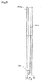
- FIG. 5 is a longitudinally cross-sectional view showing an aspirating pipette PTb for use in the closed mode.
- the aspirating pipette PTb is formed of a pipe made of stainless steel having an outer diameter of 1.5 mm, and includes a coaxial aspirating channel 31b having an inner diameter of 0.6 mm.
- the tip is sharply cut at an angle ⁇ of 30° in such a manner as to readily break through a rubber cap when the sample container SP is the closed container with the rubber cap.
- the tip of the aspirating channel 31b is sealed with a sealing member 33 made of stainless steel, and further, an aspirating port 32b having an axis perpendicular to the axis of the pipette PTb is bored at its side surface.
- a mode is set (step S1). That is to say, in the case where the sample container SP is the open container, the controller 1 executes the processing of setting "the open mode” when a user attaches the aspirating pipette PTa (see FIGS. 3 and 4 ) to the aspirating pipette holding tool 16 (see FIG. 2 ) and inputs "the open mode” in the touch panel 3 (see FIG. 1 ). In contrast, in the case where the sample container SP is the closed container, the controller 1 executes the processing of setting "the closed mode” when the user attaches the aspirating pipette PTb (see FIG. 5 ) to the aspirating pipette holding tool 16 and inputs "the closed mode” in the touch panel 3.
- the controller 1 executes the processing of judging as to whether or not the user instructs measurement start (step S2).
- step S3 the aspirating pipette ascender/descender 6 is driven by an open aspiration control, and then, the sample is aspirated from the sample container SP by the sample aspirating pump 7 (see FIG. 1 ) (step S4).
- a required reagent is added to the aspirated sample in the analyzing sample preparer 11, and thereby, the sample to be analyzed is prepared (step S5).
- the electric and/or optical characteristics, that is, the analyzing data of the prepared sample to be analyzed is detected by the analyzing data detector 12 (step S6).
- the controller 1 analyzes the sample based on the analyzing data, and then, the analysis result is displayed on the liquid crystal display 4 in the input/output unit 2 (steps S7 and S8).
- step S3 if it is determined in step S3 that "the closed mode" is set, the control routine proceeds to step S9.
- the aspirating pipette ascender/descender 6 is driven by a closed aspiration control, and then, the sample is aspirated from the sample container SP by the sample aspirating pump 7. Thereafter, the control routine proceeds to step S5.
- the processing from steps S1 to S9 is repeated in sequence.
- step S4 the processing procedures of "the open aspiration control" in step S4 will be explained below in reference to the flowchart illustrated in FIG. 7 .
- the controller 1 outputs a signal for setting the motor driving current (i.e., the magnitude of the drive pulse) to I 1 .
- the motor current varying circuit 10 sets the motor driving current in the motor drive circuit 9 to I 1 (step S11).
- the drive pulse is supplied to each of the phases of the stepping motor 25 from the motor drive circuit 9 at a predetermined frequency and the motor driving current I 1 , thereby driving the stepping motor 25 in such a manner that the aspirating pipette PT is moved to an initial position.
- step S12 When the sensor 29 (see FIG. 2 ) is actuated, that is, when the aspirating pipette PT reaches the initial position, the stepping motor 25 is stopped (step S12).
- the stepping motor 25 is started to be driven in a direction in which the aspirating pipette PT is descended by the drive pulse of the motor driving current I 1 (step S13), and then, the stepping motor 25 is driven by the drive pulse whose pulse number N 1 ( ⁇ N 0 ) has been programmed in advance (step S14).
- No designates the number of drive pulses of the stepping motor 25 corresponding to a distance from the tip of the aspirating pipette PT at the initial position to the bottom of the sample container SP. Consequently, at this time, the tip of the aspirating pipette PT has not reached the bottom of the sample container SP yet.
- the motor current varying circuit 10 sets a motor driving current I 2 , which has been programmed in advance, in the motor drive circuit 9 as a new motor driving current based on the output from the controller 1.
- the motor driving current I 2 is smaller than the motor driving current I 1 (step S15).
- the stepping motor 25 is started to be driven by the drive pulse of the motor driving current I 2 in a direction in which the aspirating pipette PT is descended (step S16).
- step S17 the energization to the stepping motor 25 is stopped (step S17).
- N 1 + N 2 > No the tip of the aspirating pipette PT reaches the bottom of the sample container SP, and thereafter, the drive pulse whose pulse number is (N 1 + N 2 - N 0 ) is supplied to the stepping motor 25, thereby causing the loss of synchronization of the stepping motor 25 by reactive force exerted from the sample container SP on the aspirating pipette PT.
- the motor driving current of the stepping motor 25 during the loss of synchronization is I 2 , which is set sufficiently smaller than I 1 , the output torque of the stepping motor 25 is small, and therefore, there occurs no damage on the aspirating pipette PT, the sample container SP or the stepping motor 25.
- the sample is aspirated from the sample container SP via the aspirating pipette PT by the sample aspirating pump 7 (step S18).
- the motor driving current of the stepping motor 25 is returned to I 1 (step S20).
- the stepping motor 25 is driven at the drive pulse of the motor driving current I 1 , so that the aspirating pipette PT is ascended up to the initial position, that is, until the sensor 29 is actuated (step S21).
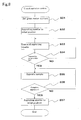
- step S9 the processing procedures of "the closed aspiration control" in step S9 will be explained below in reference to the flowchart illustrated in FIG. 8 .
- the controller 1 outputs the signal for setting the motor driving current to I 1 .
- the motor current varying circuit 10 sets the motor driving current in the motor drive circuit 9 to I 1 (step S31).
- the drive pulse is supplied to each of the phases of the stepping motor 25 from the motor drive circuit 9 at a predetermined frequency and the motor driving current I 1 , thereby driving the stepping motor 25 in a direction in which the aspirating pipette PT is ascended or descended.
- step S32 When the sensor 29 (see FIG. 2 ) is actuated, that is, when the aspirating pipette PT reaches the initial position, the stepping motor 25 is stopped (step S32).
- the distance from the tip of the aspirating pipette PT at the initial position to the bottom of the sample container SP corresponds to the number N 0 of drive pulses of the stepping motor 25.
- the stepping motor 25 is started to be driven in the direction in which the aspirating pipette PT is descended (step S33), and then, the stepping motor 25 is driven by the drive pulse whose pulse number N 3 ( ⁇ N 0 ) has been programmed in advance (step S34).
- the sample is aspirated from the sample container SP via the aspirating pipette PT by the sample aspirating pump 7 (step S35).
- the stepping motor 25 is driven at the drive pulse of the motor driving current I 1 , so that the aspirating pipette PT is ascended up to the initial position, that is, until the sensor 29 is actuated (step S37).
- the tip of the aspirating pipette PT is securely pressed against the bottom of the liquid container SP by utilizing the loss of synchronization of the stepping motor 25, thereby securing the contact between the tip of the aspirating pipette PT and the liquid container SP with the remarkably simple configuration, so as to effectively aspirate a fine quantity of sample.
- the motor driving current may be set to I 2 before the start of the descending of the aspirating pipette, and further, the aspirating pipette may be brought into contact with the bottom of the sample container SP at the motor driving current I 2 , thereby leading to the loss of the synchronization of the stepping motor.
- the present invention is not limited to this: for example, a current different from the current I 1 may be used as the motor driving current in the closed aspiration control.
- a current larger than the current I 1 should be used.
- a fluid drive source such as an air motor or an air cylinder may be used as the drive source.
- liquid aspirator 5 has been exemplified by the device for aspirating the blood from the sample container SP containing the blood therein in the above-described preferred embodiment, the liquid aspirator according to the present invention may be applied to a device for aspirating a liquid reagent from a reagent container containing the liquid reagent.
Landscapes
- Physics & Mathematics (AREA)
- Health & Medical Sciences (AREA)
- Life Sciences & Earth Sciences (AREA)
- Chemical & Material Sciences (AREA)
- Analytical Chemistry (AREA)
- Biochemistry (AREA)
- General Health & Medical Sciences (AREA)
- General Physics & Mathematics (AREA)
- Immunology (AREA)
- Pathology (AREA)
- Automatic Analysis And Handling Materials Therefor (AREA)
- Sampling And Sample Adjustment (AREA)
- Devices For Use In Laboratory Experiments (AREA)
- Investigating Or Analysing Materials By Optical Means (AREA)
Applications Claiming Priority (3)
| Application Number | Priority Date | Filing Date | Title |
|---|---|---|---|
| JP2003197379A JP4351875B2 (ja) | 2003-07-15 | 2003-07-15 | 液体吸引装置とそれを備えた分析装置 |
| EP04016451A EP1498735B1 (fr) | 2003-07-15 | 2004-07-13 | Pipette aspirateur de liquide, et analyseur avec une telle pipette |
| EP07015494A EP1855115B1 (fr) | 2003-07-15 | 2004-07-13 | Aspirateur de liquides et analyseur le comprenant |
Related Parent Applications (3)
| Application Number | Title | Priority Date | Filing Date |
|---|---|---|---|
| EP07015494A Division EP1855115B1 (fr) | 2003-07-15 | 2004-07-13 | Aspirateur de liquides et analyseur le comprenant |
| EP04016451.9 Division | 2004-07-13 | ||
| EP07015494.3 Division | 2007-08-07 |
Publications (3)
| Publication Number | Publication Date |
|---|---|
| EP1933154A2 true EP1933154A2 (fr) | 2008-06-18 |
| EP1933154A3 EP1933154A3 (fr) | 2009-09-30 |
| EP1933154B1 EP1933154B1 (fr) | 2013-02-27 |
Family
ID=33475499
Family Applications (3)
| Application Number | Title | Priority Date | Filing Date |
|---|---|---|---|
| EP04016451A Expired - Lifetime EP1498735B1 (fr) | 2003-07-15 | 2004-07-13 | Pipette aspirateur de liquide, et analyseur avec une telle pipette |
| EP07015494A Expired - Lifetime EP1855115B1 (fr) | 2003-07-15 | 2004-07-13 | Aspirateur de liquides et analyseur le comprenant |
| EP08006055A Expired - Lifetime EP1933154B1 (fr) | 2003-07-15 | 2004-07-13 | Aspirateur de liquides et analyseur le comprenant |
Family Applications Before (2)
| Application Number | Title | Priority Date | Filing Date |
|---|---|---|---|
| EP04016451A Expired - Lifetime EP1498735B1 (fr) | 2003-07-15 | 2004-07-13 | Pipette aspirateur de liquide, et analyseur avec une telle pipette |
| EP07015494A Expired - Lifetime EP1855115B1 (fr) | 2003-07-15 | 2004-07-13 | Aspirateur de liquides et analyseur le comprenant |
Country Status (5)
| Country | Link |
|---|---|
| US (1) | US7981384B2 (fr) |
| EP (3) | EP1498735B1 (fr) |
| JP (1) | JP4351875B2 (fr) |
| AT (2) | ATE376677T1 (fr) |
| DE (2) | DE602004015865D1 (fr) |
Cited By (3)
| Publication number | Priority date | Publication date | Assignee | Title |
|---|---|---|---|---|
| WO2010102061A1 (fr) * | 2009-03-06 | 2010-09-10 | Dionex Corporation | Système et procédé de distribution d'échantillon fluide |
| WO2011151014A1 (fr) * | 2010-06-02 | 2011-12-08 | Chemagen Biopolymer-Technologie Ag | Dispositif et procédé de collecte intégrale de liquides à partir de récipients |
| US20120294763A1 (en) * | 2008-10-31 | 2012-11-22 | Sysmex Corporation | Specimen analyzing apparatus and specimen analyzing method |
Families Citing this family (19)
| Publication number | Priority date | Publication date | Assignee | Title |
|---|---|---|---|---|
| EP1882951B1 (fr) * | 2005-05-19 | 2017-09-27 | Universal Bio Research Co., Ltd. | Procédé de détection de quantité injectée, et appareil d injection et de surveillance d aspiration de liquide |
| US7284453B2 (en) * | 2005-07-15 | 2007-10-23 | Beckman Coulter, Inc. | Method and apparatus for maximizing liquid aspiration from small vessels |
| US7275430B2 (en) * | 2005-10-07 | 2007-10-02 | Beckman Coulter, Inc. | Method and apparatus for detecting liquid levels in liquid-storage containers |
| JP4949788B2 (ja) * | 2006-09-22 | 2012-06-13 | 富士フイルム株式会社 | 液体吸引装置 |
| CN101168160B (zh) * | 2006-10-26 | 2012-02-01 | 深圳迈瑞生物医疗电子股份有限公司 | 反应杯清洗机构 |
| CN103913585B (zh) * | 2007-03-30 | 2016-08-31 | 希森美康株式会社 | 配液器、配液方法及吸液管 |
| KR100826812B1 (ko) * | 2007-07-23 | 2008-05-02 | 주식회사 만도 | 차량의 아이스 노면에서 선회시 조향각 센서의 신호 이상검출 방법 |
| EP2221339B1 (fr) * | 2007-11-28 | 2014-04-02 | Mitsui Chemicals, Inc. | Article moulé d'une composition de résine de polypropylène renforcée par des charges |
| JP2010133924A (ja) * | 2008-10-28 | 2010-06-17 | Sysmex Corp | 液体吸引機構および試料分析装置 |
| EP2410340B1 (fr) | 2009-03-18 | 2019-06-26 | Sysmex Corporation | Analyseur d'échantillon |
| EP2261676B8 (fr) * | 2009-06-12 | 2015-03-18 | CTC Analytics AG | Outil de manipulation d'un échantillon |
| JP5426498B2 (ja) * | 2010-08-18 | 2014-02-26 | シスメックス株式会社 | 検体吸引装置 |
| CH704388A2 (de) * | 2011-01-27 | 2012-07-31 | Tecan Trading Ag | Einstellverfahren für Mikroplatten-Waschgeräte. |
| JP5850625B2 (ja) * | 2011-03-02 | 2016-02-03 | シスメックス株式会社 | 分析装置及び位置確認方法 |
| EP2631281A3 (fr) * | 2012-02-27 | 2013-09-18 | Rolls-Royce plc | Appareil et procédé de conditionnement d'un fiul hydrocarbonné contenant de l'oxygène |
| US11372014B2 (en) * | 2016-05-12 | 2022-06-28 | Siemens Healthcare Diagnostics Inc. | Clinical analyzer probe crash detection mechanism and process |
| EP4046720A1 (fr) * | 2021-02-22 | 2022-08-24 | Bia Separations D.O.O. | Rotor de centrifugeuse, centrifugeuse ou ultracentrifugeuse comprenant un rotor de centrifugeuse, aiguille de retrait d'échantillon, procédé de retrait in situ d'un échantillon d'un tube de centrifugeuse |
| CN113267380B (zh) * | 2021-05-18 | 2023-03-21 | 永高股份有限公司 | 一种供水管网定点水质检测装置 |
| CN114813088B (zh) * | 2022-05-07 | 2024-05-28 | 成都开图医疗系统科技有限公司 | 一种移液器用tip头检测方法及移液器 |
Citations (2)
| Publication number | Priority date | Publication date | Assignee | Title |
|---|---|---|---|---|
| JPH11271322A (ja) | 1998-03-24 | 1999-10-08 | Olympus Optical Co Ltd | 液体吸引方法 |
| WO2000058736A1 (fr) | 1999-03-25 | 2000-10-05 | Coulter International Corp. | Dispositif d'aspiration de liquide dans un recipient |
Family Cites Families (20)
| Publication number | Priority date | Publication date | Assignee | Title |
|---|---|---|---|---|
| US4325909A (en) * | 1980-10-24 | 1982-04-20 | Coulter Electronics, Inc. | Fluid transfer apparatus |
| FR2474697B1 (fr) * | 1980-01-28 | 1985-07-26 | Coulter Electronics | Mecanisme de transfert de fluide a plusieurs positions |
| JPS6459158A (en) | 1987-08-31 | 1989-03-06 | Shimadzu Corp | Automatic sample introduction apparatus |
| EP0452892B1 (fr) * | 1990-04-18 | 1996-03-06 | E.I. Du Pont De Nemours And Company | Appareil pour échantillonnage de tubes ouverts et fermés |
| US5141871A (en) * | 1990-05-10 | 1992-08-25 | Pb Diagnostic Systems, Inc. | Fluid dispensing system with optical locator |
| WO1994008759A1 (fr) * | 1992-10-16 | 1994-04-28 | Thomas Jefferson University | Procede et appareil d'execution robotique de reactions de sequencage de didesoxynucleotides de sanger |
| SE9502183D0 (sv) * | 1995-06-15 | 1995-06-15 | Pharmacia Ab | Säkerhetsanordning vid en pipettarm |
| JPH11304819A (ja) | 1998-04-23 | 1999-11-05 | Aloka Co Ltd | ノズル装置 |
| DE19823283A1 (de) | 1998-05-25 | 1999-12-02 | Basf Ag | Pipettierautomat |
| JP3451014B2 (ja) | 1998-06-05 | 2003-09-29 | アロカ株式会社 | ノズル装置 |
| JP3771380B2 (ja) | 1998-08-31 | 2006-04-26 | シスメックス株式会社 | 液体吸引装置 |
| JP3836609B2 (ja) | 1998-09-14 | 2006-10-25 | シスメックス株式会社 | 液体吸引装置 |
| EP0984285B1 (fr) * | 1998-08-31 | 2004-01-07 | Sysmex Corporation | Aspirateur d'échantillons avec coopération de deux moteurs |
| JP2000074928A (ja) | 1998-08-31 | 2000-03-14 | Sysmex Corp | 液体吸引管 |
| US6270726B1 (en) * | 1999-09-30 | 2001-08-07 | Dpc Cirrus, Inc. | Tube bottom sensing for small fluid samples |
| DE19960834B4 (de) * | 1999-12-16 | 2006-10-26 | Agie S.A., Losone | Verfahren und Vorrichtung zur Störungserfassung, insbesondere zur Kollisionserfassung, im Antriebssystem einer numerisch gesteuerten Werkzeugmaschine |
| JP3674503B2 (ja) * | 2000-11-28 | 2005-07-20 | 株式会社日立製作所 | 自動分析装置及び自動分析装置の液面検出方法 |
| JP4613283B2 (ja) | 2001-02-02 | 2011-01-12 | アークレイ株式会社 | 微量液の供給装置および混合装置 |
| EP1291659A3 (fr) * | 2001-09-06 | 2008-05-21 | Sysmex Corporation | Appareil d'analyse automatique et ses composants |
| US7284453B2 (en) * | 2005-07-15 | 2007-10-23 | Beckman Coulter, Inc. | Method and apparatus for maximizing liquid aspiration from small vessels |
-
2003
- 2003-07-15 JP JP2003197379A patent/JP4351875B2/ja not_active Expired - Lifetime
-
2004
- 2004-07-13 AT AT04016451T patent/ATE376677T1/de not_active IP Right Cessation
- 2004-07-13 EP EP04016451A patent/EP1498735B1/fr not_active Expired - Lifetime
- 2004-07-13 DE DE602004015865T patent/DE602004015865D1/de not_active Expired - Lifetime
- 2004-07-13 EP EP07015494A patent/EP1855115B1/fr not_active Expired - Lifetime
- 2004-07-13 DE DE602004009640T patent/DE602004009640T2/de not_active Expired - Lifetime
- 2004-07-13 AT AT07015494T patent/ATE404870T1/de not_active IP Right Cessation
- 2004-07-13 EP EP08006055A patent/EP1933154B1/fr not_active Expired - Lifetime
- 2004-07-14 US US10/890,879 patent/US7981384B2/en active Active
Patent Citations (2)
| Publication number | Priority date | Publication date | Assignee | Title |
|---|---|---|---|---|
| JPH11271322A (ja) | 1998-03-24 | 1999-10-08 | Olympus Optical Co Ltd | 液体吸引方法 |
| WO2000058736A1 (fr) | 1999-03-25 | 2000-10-05 | Coulter International Corp. | Dispositif d'aspiration de liquide dans un recipient |
Cited By (7)
| Publication number | Priority date | Publication date | Assignee | Title |
|---|---|---|---|---|
| US20120294763A1 (en) * | 2008-10-31 | 2012-11-22 | Sysmex Corporation | Specimen analyzing apparatus and specimen analyzing method |
| US9068956B2 (en) * | 2008-10-31 | 2015-06-30 | Sysmex Corporation | Specimen analyzing apparatus and specimen analyzing method |
| WO2010102061A1 (fr) * | 2009-03-06 | 2010-09-10 | Dionex Corporation | Système et procédé de distribution d'échantillon fluide |
| US8776621B2 (en) | 2009-03-06 | 2014-07-15 | Dionex Corporation | Fluid sample delivery system and method |
| WO2011151014A1 (fr) * | 2010-06-02 | 2011-12-08 | Chemagen Biopolymer-Technologie Ag | Dispositif et procédé de collecte intégrale de liquides à partir de récipients |
| AU2011260626B2 (en) * | 2010-06-02 | 2013-10-10 | Perkinelmer Chemagen Technologie Gmbh | Apparatus and method for remainder-less uptake of liquids from vessels |
| US9108191B2 (en) | 2010-06-02 | 2015-08-18 | Perkinelmer Chemagen Technologie Gmbh | Device and method for the complete uptake of liquids from vessels |
Also Published As
| Publication number | Publication date |
|---|---|
| DE602004009640D1 (de) | 2007-12-06 |
| EP1855115A1 (fr) | 2007-11-14 |
| EP1498735A3 (fr) | 2006-04-12 |
| JP4351875B2 (ja) | 2009-10-28 |
| EP1498735A2 (fr) | 2005-01-19 |
| ATE404870T1 (de) | 2008-08-15 |
| US20050013744A1 (en) | 2005-01-20 |
| EP1933154A3 (fr) | 2009-09-30 |
| DE602004009640T2 (de) | 2008-08-28 |
| DE602004015865D1 (de) | 2008-09-25 |
| US7981384B2 (en) | 2011-07-19 |
| ATE376677T1 (de) | 2007-11-15 |
| EP1498735B1 (fr) | 2007-10-24 |
| EP1933154B1 (fr) | 2013-02-27 |
| JP2005037157A (ja) | 2005-02-10 |
| EP1855115B1 (fr) | 2008-08-13 |
Similar Documents
| Publication | Publication Date | Title |
|---|---|---|
| EP1498735B1 (fr) | Pipette aspirateur de liquide, et analyseur avec une telle pipette | |
| CN110398600B (zh) | 一种血样自动混匀装置及血细胞分析设备 | |
| US6363802B1 (en) | Apparatus for aspirating liquid from a vessel | |
| CN110398599B (zh) | 一种全自动进样血细胞分析测量方法及装置 | |
| EP2306206B1 (fr) | Appareil de traitement d'échantillons sanguins et procédé de traitement d'échantillons sanguins | |
| JPH087222B2 (ja) | 自動分注希釈装置 | |
| EP2045607B1 (fr) | Analyseur automatique | |
| CN108982886B (zh) | 样本分析仪进样结构、样本分析仪及采样方法 | |
| EP0169071B1 (fr) | Procédé et dispositif de détection de la pénétration dans un liquide d'une sonde utilisée pour aspirer et distribuer ce liquide | |
| JP4781054B2 (ja) | 血液試料吸引装置を備える血液分析装置 | |
| JP3700402B2 (ja) | 吸引流路の詰まりまたは吸引量不足の検出方法、試料液吸引装置、及び分注装置 | |
| JP4755927B2 (ja) | 血液試料中の血球測定方法及び装置 | |
| US7931789B2 (en) | Device for charging separation buffer liquid to microchip, and microchip processing device equipped with the charging device, electrophoresis method in capillary channel and its microchip processing device | |
| JP3687019B2 (ja) | サンプリング装置 | |
| EP2136210A1 (fr) | Analyseur d'échantillon de fluide corporel | |
| EP2244093A1 (fr) | Dispositif a buse et analyseur d'echantillons liquides | |
| EP4212856B1 (fr) | Dispositif de chimioluminescence entièrement automatique de test de point d'intervention (poct) basé sur une technologie de prétraitement parallèle multicanal | |
| JPH0810214B2 (ja) | 液体クロマトグラフィー用希釈試料調製装置 | |
| JPH0755815A (ja) | 試料容器回転装置 | |
| CN116381261A (zh) | 一种全自动血栓弹力图仪 | |
| CN213456549U (zh) | 一种血栓弹力图仪 | |
| JPH0915114A (ja) | 試料導入装置 | |
| JPH051817Y2 (fr) | ||
| JPH01202664A (ja) | 容器洗浄装置 | |
| JPH08313540A (ja) | 臨床用生化学自動分析装置 |
Legal Events
| Date | Code | Title | Description |
|---|---|---|---|
| PUAI | Public reference made under article 153(3) epc to a published international application that has entered the european phase |
Free format text: ORIGINAL CODE: 0009012 |
|
| 17P | Request for examination filed |
Effective date: 20080328 |
|
| AC | Divisional application: reference to earlier application |
Ref document number: 1498735 Country of ref document: EP Kind code of ref document: P Ref document number: 1855115 Country of ref document: EP Kind code of ref document: P |
|
| AK | Designated contracting states |
Kind code of ref document: A2 Designated state(s): AT BE BG CH CY CZ DE DK EE ES FI FR GB GR HU IE IT LI LU MC NL PL PT RO SE SI SK TR |
|
| AX | Request for extension of the european patent |
Extension state: AL HR LT LV MK |
|
| RIN1 | Information on inventor provided before grant (corrected) |
Inventor name: NAGAI, TAKAAKI C/O SYSMEX CORPORATION Inventor name: YOSHIDA NORIYOSHI C/O SYSMEX CORPORATION |
|
| PUAL | Search report despatched |
Free format text: ORIGINAL CODE: 0009013 |
|
| AK | Designated contracting states |
Kind code of ref document: A3 Designated state(s): AT BE BG CH CY CZ DE DK EE ES FI FR GB GR HU IE IT LI LU MC NL PL PT RO SE SI SK TR |
|
| AX | Request for extension of the european patent |
Extension state: AL HR LT LV MK |
|
| AKX | Designation fees paid |
Designated state(s): AT BE BG CH CY CZ DE DK EE ES FI FR GB GR HU IE IT LI LU MC NL PL PT RO SE SI SK TR |
|
| 17Q | First examination report despatched |
Effective date: 20101122 |
|
| GRAP | Despatch of communication of intention to grant a patent |
Free format text: ORIGINAL CODE: EPIDOSNIGR1 |
|
| GRAS | Grant fee paid |
Free format text: ORIGINAL CODE: EPIDOSNIGR3 |
|
| GRAA | (expected) grant |
Free format text: ORIGINAL CODE: 0009210 |
|
| AC | Divisional application: reference to earlier application |
Ref document number: 1855115 Country of ref document: EP Kind code of ref document: P Ref document number: 1498735 Country of ref document: EP Kind code of ref document: P |
|
| AK | Designated contracting states |
Kind code of ref document: B1 Designated state(s): AT BE BG CH CY CZ DE DK EE ES FI FR GB GR HU IE IT LI LU MC NL PL PT RO SE SI SK TR |
|
| REG | Reference to a national code |
Ref country code: GB Ref legal event code: FG4D |
|
| REG | Reference to a national code |
Ref country code: CH Ref legal event code: EP |
|
| REG | Reference to a national code |
Ref country code: AT Ref legal event code: REF Ref document number: 598761 Country of ref document: AT Kind code of ref document: T Effective date: 20130315 |
|
| REG | Reference to a national code |
Ref country code: IE Ref legal event code: FG4D |
|
| REG | Reference to a national code |
Ref country code: DE Ref legal event code: R096 Ref document number: 602004041206 Country of ref document: DE Effective date: 20130425 |
|
| REG | Reference to a national code |
Ref country code: AT Ref legal event code: MK05 Ref document number: 598761 Country of ref document: AT Kind code of ref document: T Effective date: 20130227 |
|
| PG25 | Lapsed in a contracting state [announced via postgrant information from national office to epo] |
Ref country code: AT Free format text: LAPSE BECAUSE OF FAILURE TO SUBMIT A TRANSLATION OF THE DESCRIPTION OR TO PAY THE FEE WITHIN THE PRESCRIBED TIME-LIMIT Effective date: 20130227 Ref country code: BG Free format text: LAPSE BECAUSE OF FAILURE TO SUBMIT A TRANSLATION OF THE DESCRIPTION OR TO PAY THE FEE WITHIN THE PRESCRIBED TIME-LIMIT Effective date: 20130527 Ref country code: SE Free format text: LAPSE BECAUSE OF FAILURE TO SUBMIT A TRANSLATION OF THE DESCRIPTION OR TO PAY THE FEE WITHIN THE PRESCRIBED TIME-LIMIT Effective date: 20130227 Ref country code: ES Free format text: LAPSE BECAUSE OF FAILURE TO SUBMIT A TRANSLATION OF THE DESCRIPTION OR TO PAY THE FEE WITHIN THE PRESCRIBED TIME-LIMIT Effective date: 20130607 |
|
| REG | Reference to a national code |
Ref country code: NL Ref legal event code: VDEP Effective date: 20130227 |
|
| PG25 | Lapsed in a contracting state [announced via postgrant information from national office to epo] |
Ref country code: PT Free format text: LAPSE BECAUSE OF FAILURE TO SUBMIT A TRANSLATION OF THE DESCRIPTION OR TO PAY THE FEE WITHIN THE PRESCRIBED TIME-LIMIT Effective date: 20130627 Ref country code: GR Free format text: LAPSE BECAUSE OF FAILURE TO SUBMIT A TRANSLATION OF THE DESCRIPTION OR TO PAY THE FEE WITHIN THE PRESCRIBED TIME-LIMIT Effective date: 20130528 Ref country code: SI Free format text: LAPSE BECAUSE OF FAILURE TO SUBMIT A TRANSLATION OF THE DESCRIPTION OR TO PAY THE FEE WITHIN THE PRESCRIBED TIME-LIMIT Effective date: 20130227 Ref country code: PL Free format text: LAPSE BECAUSE OF FAILURE TO SUBMIT A TRANSLATION OF THE DESCRIPTION OR TO PAY THE FEE WITHIN THE PRESCRIBED TIME-LIMIT Effective date: 20130227 Ref country code: BE Free format text: LAPSE BECAUSE OF FAILURE TO SUBMIT A TRANSLATION OF THE DESCRIPTION OR TO PAY THE FEE WITHIN THE PRESCRIBED TIME-LIMIT Effective date: 20130227 Ref country code: FI Free format text: LAPSE BECAUSE OF FAILURE TO SUBMIT A TRANSLATION OF THE DESCRIPTION OR TO PAY THE FEE WITHIN THE PRESCRIBED TIME-LIMIT Effective date: 20130227 |
|
| PG25 | Lapsed in a contracting state [announced via postgrant information from national office to epo] |
Ref country code: EE Free format text: LAPSE BECAUSE OF FAILURE TO SUBMIT A TRANSLATION OF THE DESCRIPTION OR TO PAY THE FEE WITHIN THE PRESCRIBED TIME-LIMIT Effective date: 20130227 Ref country code: SK Free format text: LAPSE BECAUSE OF FAILURE TO SUBMIT A TRANSLATION OF THE DESCRIPTION OR TO PAY THE FEE WITHIN THE PRESCRIBED TIME-LIMIT Effective date: 20130227 Ref country code: RO Free format text: LAPSE BECAUSE OF FAILURE TO SUBMIT A TRANSLATION OF THE DESCRIPTION OR TO PAY THE FEE WITHIN THE PRESCRIBED TIME-LIMIT Effective date: 20130227 Ref country code: DK Free format text: LAPSE BECAUSE OF FAILURE TO SUBMIT A TRANSLATION OF THE DESCRIPTION OR TO PAY THE FEE WITHIN THE PRESCRIBED TIME-LIMIT Effective date: 20130227 Ref country code: CZ Free format text: LAPSE BECAUSE OF FAILURE TO SUBMIT A TRANSLATION OF THE DESCRIPTION OR TO PAY THE FEE WITHIN THE PRESCRIBED TIME-LIMIT Effective date: 20130227 Ref country code: NL Free format text: LAPSE BECAUSE OF FAILURE TO SUBMIT A TRANSLATION OF THE DESCRIPTION OR TO PAY THE FEE WITHIN THE PRESCRIBED TIME-LIMIT Effective date: 20130227 |
|
| PG25 | Lapsed in a contracting state [announced via postgrant information from national office to epo] |
Ref country code: CY Free format text: LAPSE BECAUSE OF FAILURE TO SUBMIT A TRANSLATION OF THE DESCRIPTION OR TO PAY THE FEE WITHIN THE PRESCRIBED TIME-LIMIT Effective date: 20130227 |
|
| PG25 | Lapsed in a contracting state [announced via postgrant information from national office to epo] |
Ref country code: IT Free format text: LAPSE BECAUSE OF FAILURE TO SUBMIT A TRANSLATION OF THE DESCRIPTION OR TO PAY THE FEE WITHIN THE PRESCRIBED TIME-LIMIT Effective date: 20130227 |
|
| PLBE | No opposition filed within time limit |
Free format text: ORIGINAL CODE: 0009261 |
|
| STAA | Information on the status of an ep patent application or granted ep patent |
Free format text: STATUS: NO OPPOSITION FILED WITHIN TIME LIMIT |
|
| 26N | No opposition filed |
Effective date: 20131128 |
|
| PG25 | Lapsed in a contracting state [announced via postgrant information from national office to epo] |
Ref country code: MC Free format text: LAPSE BECAUSE OF FAILURE TO SUBMIT A TRANSLATION OF THE DESCRIPTION OR TO PAY THE FEE WITHIN THE PRESCRIBED TIME-LIMIT Effective date: 20130227 |
|
| REG | Reference to a national code |
Ref country code: CH Ref legal event code: PL |
|
| REG | Reference to a national code |
Ref country code: DE Ref legal event code: R097 Ref document number: 602004041206 Country of ref document: DE Effective date: 20131128 |
|
| REG | Reference to a national code |
Ref country code: IE Ref legal event code: MM4A |
|
| PG25 | Lapsed in a contracting state [announced via postgrant information from national office to epo] |
Ref country code: LI Free format text: LAPSE BECAUSE OF NON-PAYMENT OF DUE FEES Effective date: 20130731 Ref country code: CH Free format text: LAPSE BECAUSE OF NON-PAYMENT OF DUE FEES Effective date: 20130731 |
|
| PG25 | Lapsed in a contracting state [announced via postgrant information from national office to epo] |
Ref country code: IE Free format text: LAPSE BECAUSE OF NON-PAYMENT OF DUE FEES Effective date: 20130713 |
|
| PG25 | Lapsed in a contracting state [announced via postgrant information from national office to epo] |
Ref country code: TR Free format text: LAPSE BECAUSE OF FAILURE TO SUBMIT A TRANSLATION OF THE DESCRIPTION OR TO PAY THE FEE WITHIN THE PRESCRIBED TIME-LIMIT Effective date: 20130227 |
|
| PG25 | Lapsed in a contracting state [announced via postgrant information from national office to epo] |
Ref country code: HU Free format text: LAPSE BECAUSE OF FAILURE TO SUBMIT A TRANSLATION OF THE DESCRIPTION OR TO PAY THE FEE WITHIN THE PRESCRIBED TIME-LIMIT; INVALID AB INITIO Effective date: 20040713 Ref country code: LU Free format text: LAPSE BECAUSE OF NON-PAYMENT OF DUE FEES Effective date: 20130713 |
|
| REG | Reference to a national code |
Ref country code: FR Ref legal event code: PLFP Year of fee payment: 13 |
|
| REG | Reference to a national code |
Ref country code: FR Ref legal event code: PLFP Year of fee payment: 14 |
|
| REG | Reference to a national code |
Ref country code: FR Ref legal event code: PLFP Year of fee payment: 15 |
|
| PGFP | Annual fee paid to national office [announced via postgrant information from national office to epo] |
Ref country code: FR Payment date: 20230620 Year of fee payment: 20 |
|
| PGFP | Annual fee paid to national office [announced via postgrant information from national office to epo] |
Ref country code: GB Payment date: 20230601 Year of fee payment: 20 |
|
| PGFP | Annual fee paid to national office [announced via postgrant information from national office to epo] |
Ref country code: DE Payment date: 20230531 Year of fee payment: 20 |
|
| REG | Reference to a national code |
Ref country code: DE Ref legal event code: R071 Ref document number: 602004041206 Country of ref document: DE |
|
| REG | Reference to a national code |
Ref country code: GB Ref legal event code: PE20 Expiry date: 20240712 |