EP1933109A2 - Verschiebungsmessinstrument - Google Patents
Verschiebungsmessinstrument Download PDFInfo
- Publication number
- EP1933109A2 EP1933109A2 EP07024018A EP07024018A EP1933109A2 EP 1933109 A2 EP1933109 A2 EP 1933109A2 EP 07024018 A EP07024018 A EP 07024018A EP 07024018 A EP07024018 A EP 07024018A EP 1933109 A2 EP1933109 A2 EP 1933109A2
- Authority
- EP
- European Patent Office
- Prior art keywords
- displacement
- reference value
- value
- stationary
- judgment
- Prior art date
- Legal status (The legal status is an assumption and is not a legal conclusion. Google has not performed a legal analysis and makes no representation as to the accuracy of the status listed.)
- Granted
Links
Images


Classifications
-
- G—PHYSICS
- G01—MEASURING; TESTING
- G01B—MEASURING LENGTH, THICKNESS OR SIMILAR LINEAR DIMENSIONS; MEASURING ANGLES; MEASURING AREAS; MEASURING IRREGULARITIES OF SURFACES OR CONTOURS
- G01B21/00—Measuring arrangements or details thereof, where the measuring technique is not covered by the other groups of this subclass, unspecified or not relevant
- G01B21/02—Measuring arrangements or details thereof, where the measuring technique is not covered by the other groups of this subclass, unspecified or not relevant for measuring length, width, or thickness
- G01B21/04—Measuring arrangements or details thereof, where the measuring technique is not covered by the other groups of this subclass, unspecified or not relevant for measuring length, width, or thickness by measuring coordinates of points
- G01B21/045—Correction of measurements
-
- G—PHYSICS
- G01—MEASURING; TESTING
- G01B—MEASURING LENGTH, THICKNESS OR SIMILAR LINEAR DIMENSIONS; MEASURING ANGLES; MEASURING AREAS; MEASURING IRREGULARITIES OF SURFACES OR CONTOURS
- G01B5/00—Measuring arrangements characterised by the use of mechanical techniques
- G01B5/02—Measuring arrangements characterised by the use of mechanical techniques for measuring length, width or thickness
- G01B5/06—Measuring arrangements characterised by the use of mechanical techniques for measuring length, width or thickness for measuring thickness
- G01B5/061—Measuring arrangements characterised by the use of mechanical techniques for measuring length, width or thickness for measuring thickness height gauges
Definitions
- the present invention relates to a measuring tool for measuring a displacement of a movable member relative to a stationary member.
- Calipers, micrometers, indicators, test indicators, height gauges, and scales are known as digital measuring tools for measuring dimensions and the like of an object.
- Such measuring tools are provided with a stationary member, a movable member arranged movable relative to the stationary member, a detector for detecting a displacement of the movable member relative to the stationary member, and a display for displaying the displacement of the movable member relative to the stationary member detected by the detector.
- a test indicator 1 includes: a body 10; a stylus 11 penetrating the body 10 and supported swingable around a supported portion 111; an encoder 12 having an electrode 121 provided to a closer end to the body 10 of the stylus 11 and a detector head 122 which is provided to the body 10 and electrostatically coupled with the electrode 121 to detect a displacement of the stylus 11 relative to the body 10; a display 13 for digitally displaying the displacement of the stylus 11 relative to the body 10 detected by the encoder 12; and an operating section 15 for a so-called preset operation.
- the test indicator 1 arranged such is a measuring tool for measuring a height and the like of an object 2 from a displacement of the stylus 11 obtained when a contact portion 112 provided to an end of the stylus 11 is contacted to the object 2.
- the test indicator 1 can also work out a comparison and the like of a plurality of objects by carrying out the preset operation.
- the contact portion 112 of the stylus 11 is brought into contact with an upper surface of one object, and the operating section 15 is operated. The displacement then of the stylus 11 is stored as a measurement reference value. Next, the contact portion 112 of the stylus 11 is contacted to the upper surface of the other object. Consequently, the difference between the displacement of the stylus 11 at this time and the measurement reference value previously stored is displayed on the display 14, thereby enabling comparison between the heights of the two objects.
- test indicator which has a detector that electrically senses a moire fringe generated by a displacement of a stylus enabling a precise measurement
- a conventional test indicator such as one in Patent Document can not precisely determine a measurement reference value since an operating section for handling a preset operation is provided to the body.
- the horizontal axis represents time
- the vertical axis represents a displacement of the stylus.
- the curve shows the displacement of the stylus that occurs during the preset operation. An operation state and a stored measurement reference value are illustrated in a timing chart under the curve.
- Fig. 5 shows a displacement of the stylus 11 during the preset operation with a conventional test indicator 1.
- a preset operation starts with bringing the stylus 11 into a stationary state by, for example, contacting the contact portion 112 of the stylus 11 to the object.
- the stationary state marks time point to.
- an operating section 15 of the body 10 is operated.
- the operation marks time point t 1 .
- the measurement reference value is stored in response to the operation of the operating section 15, the storing takes place at time point t 2 , slightly later than time point t 1 at which the operating section 15 has been operated. Since t 2 is immediately after the operation of the operating section 15, the body 10 is vibrating considerably The displacement of the stylus 11 stored as the measurement reference value is y 1 , which is different from the displacement y 0 at an actually stationary position. Therefore, the stored measurement reference value includes an error equal to y 1 -y 0 .
- a well-known way to prevent such an error in the measurement reference value is to provide a time lag between the operation of the operating section 15 and the storing of the measurement reference value.
- Fig. 6 illustrates the displacement of the stylus 11, the operation state of the operating section 15, and the timing of storing the measurement reference value in case of the preset operation with time lags.
- Fig. 6 differs from Fig. 5 only in that a considerable time lag T is provided between t 1 and t 2 . Since the vibration of the body 10 has settled at time point t 2 after a considerable time lag T, the displacement y 0 at the actually stationary position can be stored as a measurement reference value.
- the time lag needs to be determined longer than the time it takes for the vibration of the body 10 to settle. Since the vibration of the body 10 varies in accordance with, for example, an environmental condition, there are times when the time lag T is too long with respect to a vibration continuation time To, as shown in Fig. 6 . In this case, time equivalent to T-T 0 is wasted, which is not preferable in terms of work efficiency.
- An object of the present invention is to provide a measuring tool that effectively excludes occurrence of an error in a measurement reference value during a preset operation.
- a measuring tool includes: a stationary member; a movable member arranged movable with respect to the stationary member; a detector that detects a displacement of the movable member with respect to the stationary member; a computing section that computes a measurement value from the displacement detected by the detector; a display that displays the measurement value computed by the computing section; and an operating section that gives an instruction to the computing section; in which the computing section, comprising a storage that stores the displacement detected by the detector, carries out: a preset operation in which in response to the instruction given by the operating section the displacement detected by the detector is stored in the storage as a measurement reference value and a measurement value computing operation in which a measurement reference value is computed based on a difference between the present displacement and the measurement reference value stored in the storage, and in the preset operation, judgment operation in which the movable member is judged to be stationary with respect to the stationary member when a variation of the displacement detected by the detector at an interval of a predetermined time has continuously been within a permiss
- a judgment operation is carried out, in which the movable member is judged to be stationary with respect to the stationary member when the variation of the displacement detected by the detector at an interval of the predetermined has continuously been within a permissible range for the predetermined time; and when the movable member is judged to be stationary with respect to the stationary member in the judgment operation, the measurement reference value is stored in the storage. Therefore, no time is wasted after the movable member settles stationary with respect to the stationary member before the measurement reference value is stored, and no measurement reference value is stored before the movable member becomes stationary with respect to the stationary member. Occurrence of an error in the measurement reference value during the preset operation is efficiently excluded, accordingly.
- the judgment operation comprises: a provisional reference value setting operation in which in response to the instruction given by the operating section the displacement detected by the detector is stored in the storage as a provisional measurement reference value; a continuous detection operation in which the displacement is detected by the detector at an interval of the predetermined time after the provisional reference value setting operation; a discrimination operation in which whether or not a temporal variation value that is an absolute value of the difference between the displacement detected in the continuous detection operation and the provisional reference value is within the predetermined permissible range is discriminated; and a variable changing operation in which a judgment time variable is changed based on the discrimination in the discrimination operation, and in the variable changing operation: when the temporal variation value is discriminated to be within the permissible range in the discrimination operation, the judgment time variable is changed by one unit; when the temporal variation value is discriminated not to be within the permissible range the displacement at the time is stored in the storage as a new provisional reference value and the judgment time
- the movable member in the judgment operation, is judged to be stationary with respect to the stationary member when the temporal variation value has continuously been within the permissible range while the judgment time variable is approaching the predetermined value. Therefore, the settlement of the vibration of the stationary member caused by the operation of the operating section can be judged appropriately. Occurrence of an error in the measurement reference value during the preset operation is efficiently excluded, accordingly.
- the measuring tool is a test indicator or an indicator.
- occurrence of an error in the measurement reference value in the test indicator can be efficiently excluded, the test indicator and indicator being especially vulnerable to the error in the measurement reference value as an operation of the operating section has a tendency to generate a displacement of the movable body relative to the stationary member.
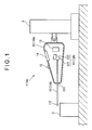
- Fig. 1 shows a sectional view of a test indicator 1 which is a measuring tool 1A according to the embodiment.
- the test indicator 1 includes: a body 10 which is a stationary member 10A; a stylus 11 which is a movable member 11 A swingably supported to the body 10; an encoder 12 which is a detector 12A for detecting a displacement of the stylus 11 relative to the body 10; a computing section 13 for computing a measurement value from the displacement of the stylus 11 relative to the body 10 detected by the encoder 12; a display 14 for displaying the measurement value computed by the computing section 13; and an operating section 15 for giving an instruction to the computing section 13.
- the body 10 is a substantially oblong casing of which one end is fixed to a stand 3 and the other end supports the stylus 11.
- the body 10 has the display 14 and the operating section 15 on an upper side and the encoder 12 and the computing section 13 inside.
- the stylus 11 penetrates through the body 10 and is swingably supported around the supported portion 111.
- a substantially spherical contact portion 112 to be in contact with a target portion of the object 2 is provided to an end of the stylus 11 opposite with respect to the body 10.
- the encoder 12 includes: an electrode 121 provided to an end of the stylus 11 adjacent to the body 10; and a detector head 122 provided to the body 10 electrostatically coupled with the electrode 121 to detect the displacement of the stylus 11.
- the display 14 is a liquid crystal display device that digitally displays a measurement value calculated by the computing section 13.
- the operating section 15 is a pressing button that gives an instruction to the computing section 13.
- Fig. 2 shows an internal arrangement of the test indicator 1.
- the computing section 13 is connected to the encoder 12, the display 14, and the operating section 15.
- the computing section 13 also includes a storage 131 for storing the displacement detected by the encoder 12.
- a preset operation in which a displacement is detected by the encoder 12 in response to an instruction from the operating section 15 and the detected displacement is stored as a measurement reference value in the storage 131, and a measurement computation operation in which a measurement value is calculated based on a difference between the present displacement and the measurement reference value stored in the storage 131 are carried out.
- a judgment operation is carried out, in which the stylus 11 is judged to be stationary with respect to the body 10 when a variation of the displacement detected by the encoder 12 at a predetermined interval has continuously been within a permissible range for a predetermined time. Also in the preset operation, when the stylus 11 is judged to be stationary with respect to the body 10, the displacement is stored as a measurement reference value in the storage 131.
- the operating section 15 is operated to give an instruction to the computing section 13 to start the preset operation. Consequently, the judgment operation (operations ST 2 to ST6), in which whether the stylus 11 is stationary relative to the body 10 or not is judged, is initiated.
- the computing section 13 given an instruction by the operating section 15, prompts the encoder 12 to detect the displacement and the storage 131 to store the detected displacement X b as a provisional reference value X a (provisional reference value setting operation).
- the displacement X b+1 is stored as a new provisional reference value X a , and the judgment time variable n is reset to a predetermined initial value ⁇ . Subsequently, when the predetermined time T 1 passes after the execution of ST3, ST3 and the following operations are repeated.
- the judgment operation includes a series of the operations ST 2 to ST6.
- a provisional reference value X a is stored as a measurement reference value X c , and the judgment time variable n is reset to the predetermined initial value ⁇ .
- the preset operation ends here.
- the computing section 13 calculates X-X c , that is, the difference between the present displacement X and the measurement reference value X c stored in the storage 131 (measurement computation operation), which is displayed as a measurement value X d by the display 14.
- Fig. 4 shows a displacement of the stylus 11 in the preset operation for the test indicator 1.
- the horizontal axis represents time
- the vertical axis represents the displacement of the stylus 11
- the curve represents the displacement of the stylus 11 that occurs during the preset operation. Shown under the curve illustrating the displacement of the stylus 11 are an operation status of the operating section 15, an operating status of the continuous detection operation and a timing at which the measurement reference value X c is stored.
- the stylus 11 is made stationary by, for example, contacting the contact portion 112 of the stylus 11 to the object 2.
- the operation marks time point to.
- an operating section 15 of the body 10 is operated.
- the operation marks time point t 1 .
- the continuous detection operation is executed after the provisional reference value setting operation, as described with reference to Fig. 3 .
- the continuous detection operation is carried out at an interval of a predetermined time T1. After the continuous detection operation, the judgment operation is executed.
- the displacement of the stylus 11 detected by the encoder 12 has approached the initial value X.
- the judgment time variable n starts to be decremented.
- the provisional reference value X a determined when the first counting took place, is stored as the measurement reference value X c .
- time required from the operation of the operating section 15 to the storage of the measurement reference value X c is approximately T 0 + ⁇ T 1 .
Landscapes
- Physics & Mathematics (AREA)
- General Physics & Mathematics (AREA)
- Length Measuring Devices With Unspecified Measuring Means (AREA)
- Length-Measuring Instruments Using Mechanical Means (AREA)
- Length Measuring Devices By Optical Means (AREA)
Applications Claiming Priority (1)
| Application Number | Priority Date | Filing Date | Title |
|---|---|---|---|
| JP2006334400A JP5192144B2 (ja) | 2006-12-12 | 2006-12-12 | 測定器 |
Publications (3)
| Publication Number | Publication Date |
|---|---|
| EP1933109A2 true EP1933109A2 (de) | 2008-06-18 |
| EP1933109A3 EP1933109A3 (de) | 2014-06-04 |
| EP1933109B1 EP1933109B1 (de) | 2017-09-20 |
Family
ID=39154039
Family Applications (1)
| Application Number | Title | Priority Date | Filing Date |
|---|---|---|---|
| EP07024018.9A Active EP1933109B1 (de) | 2006-12-12 | 2007-12-11 | Verschiebungsmessinstrument |
Country Status (4)
| Country | Link |
|---|---|
| US (1) | US7412779B2 (de) |
| EP (1) | EP1933109B1 (de) |
| JP (1) | JP5192144B2 (de) |
| CN (1) | CN101201247B (de) |
Families Citing this family (5)
| Publication number | Priority date | Publication date | Assignee | Title |
|---|---|---|---|---|
| JP5687820B2 (ja) | 2008-10-21 | 2015-03-25 | 株式会社ミツトヨ | 測定器 |
| JP5912666B2 (ja) * | 2012-02-29 | 2016-04-27 | 中央電子株式会社 | 計測装置及びその処理方法 |
| JP6189153B2 (ja) * | 2013-09-18 | 2017-08-30 | 株式会社ミツトヨ | 梃子式測定器 |
| JP2024060544A (ja) | 2022-10-19 | 2024-05-02 | 株式会社ミツトヨ | 小型測定器およびその使用方法 |
| JP2024060543A (ja) | 2022-10-19 | 2024-05-02 | 株式会社ミツトヨ | 小型測定器およびその使用方法 |
Citations (1)
| Publication number | Priority date | Publication date | Assignee | Title |
|---|---|---|---|---|
| JPH0245762U (de) | 1988-09-24 | 1990-03-29 |
Family Cites Families (19)
| Publication number | Priority date | Publication date | Assignee | Title |
|---|---|---|---|---|
| US3984006A (en) * | 1974-02-01 | 1976-10-05 | Hitachi, Ltd. | Automatic assembly control system |
| JPH022A (ja) | 1984-06-20 | 1990-01-05 | Tomio Konno | 真空フアイバー電子通信の方法とその装置 |
| US4882848A (en) * | 1987-07-30 | 1989-11-28 | Carl-Zeiss-Stiftung, Heidenheim/Brenz | Probe head for a coordinate-measuring instrument |
| DE4213588A1 (de) * | 1991-04-26 | 1992-10-29 | Mitutoyo Corp | Dimensionsmessgeraet |
| JP3422873B2 (ja) * | 1995-05-11 | 2003-06-30 | 株式会社東芝 | 振動監視装置 |
| US6369794B1 (en) * | 1998-09-09 | 2002-04-09 | Matsushita Electric Industrial Co., Ltd. | Operation indication outputting device for giving operation indication according to type of user's action |
| JP2000205852A (ja) * | 1999-01-19 | 2000-07-28 | Mitsutoyo Corp | デジタルアナログ併用表示型測定器のアナログ量測定・表示方法 |
| JP3504904B2 (ja) * | 2000-03-13 | 2004-03-08 | 株式会社ミツトヨ | 誘導型トランスデューサ及び電子ノギス |
| JP3442025B2 (ja) * | 2000-03-13 | 2003-09-02 | 株式会社ミツトヨ | 位置計測装置 |
| JP3855254B2 (ja) * | 2000-11-17 | 2006-12-06 | オムロン株式会社 | 変位センサ |
| JP2003097940A (ja) * | 2001-09-21 | 2003-04-03 | Ricoh Co Ltd | 形状測定方法、形状測定装置、形状測定用のコンピュータプログラムを格納する記憶媒体及び形状測定用のコンピュータプログラム |
| JP3961258B2 (ja) * | 2001-10-10 | 2007-08-22 | 株式会社ミツトヨ | タッチセンサ、および微細形状測定装置用プローブ |
| JP4009152B2 (ja) * | 2002-07-09 | 2007-11-14 | 株式会社ミツトヨ | 表面形状測定装置および表面形状測定方法 |
| JP4438351B2 (ja) * | 2003-08-22 | 2010-03-24 | 富士ゼロックス株式会社 | 指示入力装置、指示入力システム、指示入力方法、及びプログラム |
| US7376261B2 (en) * | 2003-11-25 | 2008-05-20 | Mitutoyo Corporation | Surface scan measuring device and method of forming compensation table for scanning probe |
| US20060293617A1 (en) * | 2004-02-05 | 2006-12-28 | Reability Inc. | Methods and apparatuses for rehabilitation and training |
| JP4382003B2 (ja) * | 2005-03-23 | 2009-12-09 | 川崎重工業株式会社 | ロボット制御装置およびロボット制御方法 |
| JP4783575B2 (ja) * | 2005-03-24 | 2011-09-28 | シチズンホールディングス株式会社 | 接触式変位測長器 |
| US7207119B1 (en) * | 2005-12-08 | 2007-04-24 | International Business Machines Corporation | Controller |
-
2006
- 2006-12-12 JP JP2006334400A patent/JP5192144B2/ja active Active
-
2007
- 2007-12-10 US US12/000,170 patent/US7412779B2/en active Active
- 2007-12-11 EP EP07024018.9A patent/EP1933109B1/de active Active
- 2007-12-11 CN CN2007101996363A patent/CN101201247B/zh active Active
Patent Citations (1)
| Publication number | Priority date | Publication date | Assignee | Title |
|---|---|---|---|---|
| JPH0245762U (de) | 1988-09-24 | 1990-03-29 |
Also Published As
| Publication number | Publication date |
|---|---|
| US7412779B2 (en) | 2008-08-19 |
| CN101201247A (zh) | 2008-06-18 |
| EP1933109A3 (de) | 2014-06-04 |
| EP1933109B1 (de) | 2017-09-20 |
| CN101201247B (zh) | 2011-11-09 |
| US20080134534A1 (en) | 2008-06-12 |
| JP2008145329A (ja) | 2008-06-26 |
| JP5192144B2 (ja) | 2013-05-08 |
Similar Documents
| Publication | Publication Date | Title |
|---|---|---|
| JP4320018B2 (ja) | 微小硬度測定法及び微小硬度計 | |
| EP1933109B1 (de) | Verschiebungsmessinstrument | |
| EP1866602B1 (de) | Messsonde | |
| EP1776716B1 (de) | Testvorrichtung | |
| JP5995488B2 (ja) | 折り曲げ加工機における板厚測定装置 | |
| KR102520191B1 (ko) | 구조물 안전진단을 위한 교량 받침장치의 변위량 측정장치 | |
| JPS6147509A (ja) | プレス機にかけられた材料の厚さを測定する方法並びに装置 | |
| CN102072701A (zh) | 一种检测零件尺寸的方法及装置 | |
| EP1927820A1 (de) | Digitale Messuhr und Verfahren zur deren Verwendung | |
| CN102944190A (zh) | 一种测量大尺寸机械零件圆度的高精度检测仪及方法 | |
| JP2013130532A (ja) | 落下衝撃検知装置 | |
| EP0641427B1 (de) | Signalverarbeitungsschaltung fur triggersonde | |
| EP1893937B1 (de) | Berührungssonde mit mitteln zum detektieren einer orientierungsänderung | |
| US8478562B2 (en) | Measuring instrument | |
| CN216405083U (zh) | 一种点焊智能盆式支座 | |
| CN105891000A (zh) | 一种用于土体分层变形监测的智能测试装置、测量标定方法和评价方法 | |
| JP2009226440A (ja) | プレス機検査装置 | |
| CN110319989A (zh) | 在役弹簧支吊架中弹簧刚度的无损检测方法 | |
| US20250321095A1 (en) | Measuring device | |
| JPH07113603A (ja) | 内側測定装置 | |
| JP4693394B2 (ja) | ワークとダイとの間の摩擦係数算出方法及び折曲げ角度検出方法並びに折曲げ加工機 | |
| JP3243524B2 (ja) | 変位量計測装置及び落下式衝撃試験装置の変位量計測装置 | |
| JP3524532B2 (ja) | 路盤の剛性測定装置 | |
| KR200223563Y1 (ko) | 간극측정장치 | |
| JP2019168356A (ja) | 表面形状測定装置 |
Legal Events
| Date | Code | Title | Description |
|---|---|---|---|
| PUAI | Public reference made under article 153(3) epc to a published international application that has entered the european phase |
Free format text: ORIGINAL CODE: 0009012 |
|
| AK | Designated contracting states |
Kind code of ref document: A2 Designated state(s): AT BE BG CH CY CZ DE DK EE ES FI FR GB GR HU IE IS IT LI LT LU LV MC MT NL PL PT RO SE SI SK TR |
|
| AX | Request for extension of the european patent |
Extension state: AL BA HR MK RS |
|
| PUAL | Search report despatched |
Free format text: ORIGINAL CODE: 0009013 |
|
| AK | Designated contracting states |
Kind code of ref document: A3 Designated state(s): AT BE BG CH CY CZ DE DK EE ES FI FR GB GR HU IE IS IT LI LT LU LV MC MT NL PL PT RO SE SI SK TR |
|
| AX | Request for extension of the european patent |
Extension state: AL BA HR MK RS |
|
| RIC1 | Information provided on ipc code assigned before grant |
Ipc: G01B 5/02 20060101AFI20140429BHEP Ipc: G01B 21/04 20060101ALN20140429BHEP |
|
| 17P | Request for examination filed |
Effective date: 20141128 |
|
| RBV | Designated contracting states (corrected) |
Designated state(s): AT BE BG CH CY CZ DE DK EE ES FI FR GB GR HU IE IS IT LI LT LU LV MC MT NL PL PT RO SE SI SK TR |
|
| AKX | Designation fees paid |
Designated state(s): DE FR GB |
|
| AXX | Extension fees paid |
Extension state: BA Extension state: RS Extension state: AL Extension state: HR Extension state: MK |
|
| REG | Reference to a national code |
Ref country code: DE Ref legal event code: R079 Ref document number: 602007052405 Country of ref document: DE Free format text: PREVIOUS MAIN CLASS: G01B0005020000 Ipc: G01B0005060000 |
|
| GRAP | Despatch of communication of intention to grant a patent |
Free format text: ORIGINAL CODE: EPIDOSNIGR1 |
|
| RIC1 | Information provided on ipc code assigned before grant |
Ipc: G01B 5/06 20060101AFI20170323BHEP Ipc: G01B 21/04 20060101ALI20170323BHEP |
|
| INTG | Intention to grant announced |
Effective date: 20170420 |
|
| GRAS | Grant fee paid |
Free format text: ORIGINAL CODE: EPIDOSNIGR3 |
|
| GRAA | (expected) grant |
Free format text: ORIGINAL CODE: 0009210 |
|
| AK | Designated contracting states |
Kind code of ref document: B1 Designated state(s): DE FR GB |
|
| REG | Reference to a national code |
Ref country code: GB Ref legal event code: FG4D |
|
| REG | Reference to a national code |
Ref country code: DE Ref legal event code: R096 Ref document number: 602007052405 Country of ref document: DE |
|
| REG | Reference to a national code |
Ref country code: FR Ref legal event code: PLFP Year of fee payment: 11 |
|
| REG | Reference to a national code |
Ref country code: DE Ref legal event code: R097 Ref document number: 602007052405 Country of ref document: DE |
|
| PLBE | No opposition filed within time limit |
Free format text: ORIGINAL CODE: 0009261 |
|
| STAA | Information on the status of an ep patent application or granted ep patent |
Free format text: STATUS: NO OPPOSITION FILED WITHIN TIME LIMIT |
|
| 26N | No opposition filed |
Effective date: 20180621 |
|
| PGFP | Annual fee paid to national office [announced via postgrant information from national office to epo] |
Ref country code: DE Payment date: 20251211 Year of fee payment: 19 |
|
| PGFP | Annual fee paid to national office [announced via postgrant information from national office to epo] |
Ref country code: GB Payment date: 20251219 Year of fee payment: 19 |
|
| PGFP | Annual fee paid to national office [announced via postgrant information from national office to epo] |
Ref country code: FR Payment date: 20251222 Year of fee payment: 19 |