EP1930272A1 - Fadenchangiervorrichtung für eine Spuleinrichtung einer Kreuzspulen herstellenden Textilmaschine - Google Patents
Fadenchangiervorrichtung für eine Spuleinrichtung einer Kreuzspulen herstellenden Textilmaschine Download PDFInfo
- Publication number
- EP1930272A1 EP1930272A1 EP07021448A EP07021448A EP1930272A1 EP 1930272 A1 EP1930272 A1 EP 1930272A1 EP 07021448 A EP07021448 A EP 07021448A EP 07021448 A EP07021448 A EP 07021448A EP 1930272 A1 EP1930272 A1 EP 1930272A1
- Authority
- EP
- European Patent Office
- Prior art keywords
- thread
- support rail
- fadenchangiervorrichtung
- laying arm
- guide
- Prior art date
- Legal status (The legal status is an assumption and is not a legal conclusion. Google has not performed a legal analysis and makes no representation as to the accuracy of the status listed.)
- Withdrawn
Links
Images


Classifications
-
- B—PERFORMING OPERATIONS; TRANSPORTING
- B65—CONVEYING; PACKING; STORING; HANDLING THIN OR FILAMENTARY MATERIAL
- B65H—HANDLING THIN OR FILAMENTARY MATERIAL, e.g. SHEETS, WEBS, CABLES
- B65H54/00—Winding, coiling, or depositing filamentary material
- B65H54/02—Winding and traversing material on to reels, bobbins, tubes, or like package cores or formers
- B65H54/28—Traversing devices; Package-shaping arrangements
- B65H54/2827—Traversing devices with a pivotally mounted guide arm
-
- B—PERFORMING OPERATIONS; TRANSPORTING
- B65—CONVEYING; PACKING; STORING; HANDLING THIN OR FILAMENTARY MATERIAL
- B65H—HANDLING THIN OR FILAMENTARY MATERIAL, e.g. SHEETS, WEBS, CABLES
- B65H2403/00—Power transmission; Driving means
- B65H2403/60—Damping means, shock absorbers
-
- B—PERFORMING OPERATIONS; TRANSPORTING
- B65—CONVEYING; PACKING; STORING; HANDLING THIN OR FILAMENTARY MATERIAL
- B65H—HANDLING THIN OR FILAMENTARY MATERIAL, e.g. SHEETS, WEBS, CABLES
- B65H2701/00—Handled material; Storage means
- B65H2701/30—Handled filamentary material
- B65H2701/31—Textiles threads or artificial strands of filaments
Definitions
- the invention relates to a Fadenchangiervoriques for a winding device of a cheese producing textile machine according to the preamble of claim 1.
- the DE 43 10 905 A1 shows and describes, for example, a so-called Riemchenfaden borrowing.
- Such Riemchenfadenimposing have two opposing, each equipped with multiple Fadenmit instructionaln, drivable belt strands, which runs up to the casserole Thread alternately at high speed from one side to the other side of the package.
- a constant or at least temporarily constant ratio between the reel speed and the speed of the thread switching must be maintained during the reel travel.
- Winding devices in which the drive of the package is separated from the drive of the Fadenchangier est are, for example in the DE 198 58 548 A1 or in the DE 199 60 024 A1 described. These known winding devices each have a single motor driven coil drive roller and a separately drivable Fadenchangier noticed on. The Fadenchangier respondeden this winding devices are designed as a finger thread guide and have a pivotally mounted Fadenverlegearm. Such Fingerfaden researching are for example in the DE 198 20 464 A1 , in the DE 103 32 399 A1 or in the EP 0 838 422 B1 described in relative detail.
- Such oscillations can be caused for example by the laying frequency of the thread-laying arm itself and / or by thread tension fluctuations, which arise through the thread balloon when draining the thread from the spinning cop and by sliding friction between the running thread and a thread guide arranged on the thread guide occurs, are transferred to the thread-laying arm.
- the drive roller of the winding device or other adjacent Spulstellenaggregate may be cause of frequencies that put the Fadenverlegearm the Fingerfaden lies into vibration, which can ultimately lead to a significant disturbance of the thread laying and thus to a reduction in the quality of the cheese to be produced.
- the present invention seeks to further develop a equipped with a finger thread guide Fadenchangiervoriques for a winding device of a cheese producing textile machine, that on the one hand, a high traversing speed of the running thread can be realized and that on the other hand it is ensured that during The thread laying can not come to disturbing vibrations of Fadenverlegarms the Fingerfaden liess.
- the support rail is arranged so that the thread transfer arm immediately applies to the support rail when it during the threading, for example, a deflection of the thread-laying arm is perpendicular to its plane of movement.
- the application of the thread-laying arm to the support rail immediately leads to a considerable reduction in the free length of the thread-laying arm, which has a positive effect both on the flexural rigidity and on the torsional rigidity of the thread-laying arm and thus on its vibration behavior.
- the support rail When applying the thread-laying arm to the support rail, there is also a change in the natural frequency of the thread-laying arm, without at the same time the mass moment of inertia of the finger thread guide is raised. That is, the support rail according to the invention prevents frequencies that arise, for example, by winding units arranged in the area of the workstation or the winding process itself, that can excite the thread laying arm to oscillate, which would adversely affect the winding process.
- the support rail is arranged in the thread running direction behind the thread laying arm of the finger thread guide, wherein during the "normal" Fadenchangierreaes a small distance between the traversing Fadenverlegearm and the stationary support rail is given. That is, the Fadenverlegearm is only on the support rail when it is deflected, for example, as a result of acting on the thread-laying arm bending forces perpendicular to its direction of movement or twisted by torsional forces in itself.
- a support rail is provided both in front of and behind the thread-laying arm.
- the support rail is fixed to the front side of the motor housing of the electric motor drive of the finger thread guide, for example on a console. That is, the support rail is easily accessible and can be easily maintained, for example, to be cleaned. In addition, in an arrangement of the support rail to a console without great effort favorable leverage ratios can be realized in the support of the thread laying arm.
- the support rail is arranged in an advantageous embodiment so that the free length of the thread laying arm is reduced when it rests against the support rail to about 1/3 of the total length of the thread laying arm.
- Such an advantageous arrangement of the thread-laying arm when bending forces lead to an application of the thread-laying arm to the support rail, automatically stabilized by shortening the free lever arm. Shortening the free length of the thread-laying arm to about 1/3 of its original length has a very positive effect on the flexural rigidity of this component, with the result that the occurrence of harmful vibrations is immediately effectively suppressed. In this way, in particular periodically occurring voltage fluctuations of the current thread, which are transmitted by thread friction on the thread laying arm and which can lead to vibrations, can be easily compensated.
- the support rail is at least partially made of an energy-absorbing, abrasion-resistant material, in particular made of a plastic.
- the support rail can either be integrally formed, that is, be made entirely of such an energy absorbing, abrasion resistant material or, as described in claim 8, be constructed multi-layer, preferably a lower, vibration-damping layer is covered by an upper protective layer, the good sliding and wear properties.
- polytetrafluoroethylene can be used as the material for the sliding and wearing layer, since such a plastic is a resistant, readily lubricious material. Since the mechanical stress of the support rail by the thread laying arm is limited in time and relatively low, such a device has a virtually unlimited life.
- support rails having a sliding and wearing layer of polytetrafluoroethylene are relatively inexpensive to produce and operate extremely reliably under all operating conditions.
- the support rail is formed in an advantageous embodiment, as described in claim 10, as a circular ring segment. Such an annular formation of the support rail favors the attachment of the support rail on the round motor housing of the thread guide drive.
- the support rail for example, by means of bolts or the like interchangeable on the motor housing of the yarn guide drive or a bracket attached to the motor housing are fixed or by means of a suitable adhesive be connected directly to the motor housing or to a corresponding console.
- the center of the annulus segment may also be staggered with respect to the pivot axis of the thread-laying arm.
- different support conditions are given at each point of the annulus segment for the thread-laying arm. That is, with such an arrangement, the length of the free lever arm changes constantly during the threading, which can prove to be quite advantageous in terms of avoiding vibrations.
- the thread-laying arm of the finger-thread guide is provided with a sliding element which, if necessary, that is, when the thread-laying arm is deflected perpendicular to its plane of movement, corresponds to the supporting rail.
- a sliding element which preferably also has a coating of polytetrafluoroethylene, the frictional resistance between Fadenverlegearm and the support rail can be further minimized.
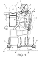
- FIG. 1 is a side view schematically a job 2 a cross-wound producing textile machine, in the present case of a so-called cross-winding machine 1, shown.
- the spinning rings 3 produced on ring spinning machines are rewound to large-volume cheeses 5 on the workstations 2 of such automatic winder 1.
- the cheeses 5 are after their completion by means of a (not shown) automatically operating service unit, preferably a cheese changer, handed over to a machine-length cheese package transport means 7 and transported to a machine end side Spulenverladestation or the like.
- such automatic packages 1 also have a logistics device in the form of a package and tube transport system 6.
- a logistics device in the form of a package and tube transport system 6.
- this bobbin and tube transport system 6 run on transport plates 11, the spinning cops 3 or empty tubes to.
- From the sleeve transport system 6 are in the FIG. 1 only the Kopszu slaughterhouse 24, the reversibly driven storage section 25, one of the leading to the winding units 2 transverse transport sections 26 and the sleeve return path 27 shown.
- Each workstation 2 of the automatic winder 1 also has a workstations computer 28, which is connected via a bus connection to a central control unit, as well as various other devices which are necessary for the proper operation of the workstations 2.
- a workstations computer 28 which is connected via a bus connection to a central control unit, as well as various other devices which are necessary for the proper operation of the workstations 2.
- One of these devices known per se is, for example, the winding device 4.
- Such a winding device 4 has inter alia a coil frame 8 which is movably mounted about a pivot axis 12. As in Fig. 1 Further indicated in the coil frame 8 freely rotatably supported cross-wound bobbin 5 during the winding operation with its surface on a support and drive roller 9, which can be acted upon by an electric motor 33.
- the electric motor 33 is connected via a control line 35 to the workstation computer 28.
- Fadenchangier listening 10 For traversing the thread 16 during the winding process a Fadenchangier listening 10 is provided.
- Fadenchangier listening 10 As in the FIG. 1 only schematically indicated Fadenchangier disturbed 10, as in particular from the Figures 2 and 3 can be seen from a finger thread guide 13, which, acted upon by the electric motor drive 14, traversing the thread 16 running on the cheese 5 between the end faces of the cheese 5.
- the thread guide drive 14 Via a control line 15, the thread guide drive 14 is connected to the workstation computer 28 in connection.
- the thread-laying arm 18 of the finger-thread guide 13 has an overall length L, this total length L being defined by the distance between the bottom of its thread-laying slot 29 and the pivot axis 30 of the thread-laying arm 18.
- the thread-changing device 10 also has at least one support rail 20, on which the thread-laying arm 18 can be supported if necessary.
- the support rail 20 is either, viewed in the direction of yarn travel F, at a distance a behind the in a Movement level E traversing thread-laying arm 18 arranged ( 3A ), or the support rail 20, as shown in FIG 3B is shown, arranged both in front of and behind the thread-laying arm 18.
- the support rails 20 are either formed in one piece and made for example of polytetrafluoroethylene or the support rails 20 are constructed in multiple layers.
- Multi-layer support rails 20 preferably have a lower damping layer 36 and a sliding and protective layer 37, wherein the sliding and protective layer 37 may be coated with polytetrafluoroethylene.
- This material known for example under the trade name "Teflon”, has very good sliding properties.
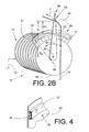
- the support rail 20 can either be attached to the motor housing 21 of the yarn guide drive 13, or, as in the 2a and 2 B indicated, releasably or permanently attached to a bracket 22 of the motor housing 21 of the thread guide drive 13.
- the support rail 20 is arranged in the direction F of the thread 16 behind the thread-laying arm 18. That is, the accumulating on the cheese 5 thread 16 passes through a Fadenleitkontur 31 in the thread-laying slot 29 of the thread-laying arm 18 and is constantly traversed by the traversing Fadenverlegearm 18 between two reversal areas.
- the design according to the invention ensures that the thread-changing device operates largely friction-free in "normal" operation, and ensures, if necessary, that the generation of vibrations is immediately and effectively counteracted. That is, if, in particular on the yarn friction bending stresses are transmitted to the thread-laying arm 18, which would build up without harmful action to harmful vibrations, the Fadenverlegearm 18 applies to the support rail 20, which immediately to a significant increase in the bending stiffness of Fadenverlegarms 18th and thus leads to a suppression of the vibrations. In this way, it is already prevented in the approach that harmful vibrations can occur in the area of the finger thread guide, which not only could damage the thread-changing device but could also adversely affect the winding result.
- the support rail 20 is preferably formed annularly, wherein the center of the annulus segment 17 is arranged either congruent with the pivot axis 30 of the finger thread guide 13, as shown in Fig. 2a is shown, or the center 38 of the annulus segment 17 is offset relative to the pivot axis 30 ( 2B ). Both variants each have advantages and disadvantages. If the center of the annulus segment 17, for example, congruent with the pivot axis 30 of the finger thread guide 13th is ensured that over the entire traverse width always the same support conditions are given.
Landscapes
- Winding Filamentary Materials (AREA)
Applications Claiming Priority (1)
| Application Number | Priority Date | Filing Date | Title |
|---|---|---|---|
| DE200610057407 DE102006057407A1 (de) | 2006-12-04 | 2006-12-04 | Fadenchangiervorrichtung für eine Spuleinrichtung einer Kreuzspulen herstellenden Textilmaschine |
Publications (1)
| Publication Number | Publication Date |
|---|---|
| EP1930272A1 true EP1930272A1 (de) | 2008-06-11 |
Family
ID=39198307
Family Applications (1)
| Application Number | Title | Priority Date | Filing Date |
|---|---|---|---|
| EP07021448A Withdrawn EP1930272A1 (de) | 2006-12-04 | 2007-11-05 | Fadenchangiervorrichtung für eine Spuleinrichtung einer Kreuzspulen herstellenden Textilmaschine |
Country Status (4)
| Country | Link |
|---|---|
| EP (1) | EP1930272A1 (ja) |
| JP (1) | JP2008137816A (ja) |
| CN (1) | CN101195451A (ja) |
| DE (1) | DE102006057407A1 (ja) |
Cited By (1)
| Publication number | Priority date | Publication date | Assignee | Title |
|---|---|---|---|---|
| EP2537787A1 (de) * | 2011-06-25 | 2012-12-26 | Oerlikon Textile GmbH & Co. KG | Fingerfadenführer |
Families Citing this family (2)
| Publication number | Priority date | Publication date | Assignee | Title |
|---|---|---|---|---|
| DE102009017857A1 (de) | 2009-04-17 | 2010-10-21 | Oerlikon Textile Gmbh & Co. Kg | Fadenchangiereinrichtung |
| CN105366434A (zh) * | 2015-11-09 | 2016-03-02 | 浙江日发纺织机械股份有限公司 | 一种摇臂导纱装置 |
Citations (6)
| Publication number | Priority date | Publication date | Assignee | Title |
|---|---|---|---|---|
| WO1992008664A1 (en) * | 1990-11-09 | 1992-05-29 | James Edward Freeman | Thread package building |
| EP0838422A1 (de) * | 1996-10-28 | 1998-04-29 | Ssm Schärer Schweiter Mettler Ag | Vorrichtung zum Aufwickeln eines Fadens auf eine Spule |
| DE19960024A1 (de) * | 1998-12-18 | 2000-06-21 | Schlafhorst & Co W | Fadenführer zum traversierenden Zuführen eines Fadens zu einer rotierend angetriebenen Auflaufspule |
| DE10031646A1 (de) * | 1999-07-23 | 2001-01-25 | Rieter Ag Maschf | Fadenchangierdisposition |
| EP1728748A1 (de) * | 2005-06-04 | 2006-12-06 | Saurer GmbH & Co. KG | Fadenchangiervorrichtung für eine Spuleinrichtung einer Kreuzspulen herstellenden Textilmaschine |
| WO2007007004A2 (fr) * | 2005-07-11 | 2007-01-18 | Ritm | Dispositif de va-et-vient a bras oscillant |
Family Cites Families (5)
| Publication number | Priority date | Publication date | Assignee | Title |
|---|---|---|---|---|
| DE4237860A1 (de) * | 1992-11-10 | 1994-05-11 | Schlafhorst & Co W | Fadenführungstrommel |
| DE4310905A1 (de) * | 1993-04-02 | 1994-10-06 | Schlafhorst & Co W | Verfahren und Vorrichtung zur Fadenverlegung auf einer Kreuzspule |
| CH692624A5 (de) * | 1998-03-19 | 2002-08-30 | Textilma Ag | Elektrischer Schwenkmotor insbesondere für eine Textilmaschine. |
| DE19858548A1 (de) * | 1998-12-18 | 2000-06-21 | Schlafhorst & Co W | Fadenführer zum traversierenden Zuführen eines Fadens zu einer rotierend angetriebenen Auflaufspule |
| DE10332399A1 (de) * | 2003-07-17 | 2005-02-03 | Saurer Gmbh & Co. Kg | Energiespeicher für einen Fingerfadenführer einer Kreuzspulen herstellenden Textilmaschine |
-
2006
- 2006-12-04 DE DE200610057407 patent/DE102006057407A1/de not_active Withdrawn
-
2007
- 2007-11-05 EP EP07021448A patent/EP1930272A1/de not_active Withdrawn
- 2007-11-27 CN CNA2007101946307A patent/CN101195451A/zh active Pending
- 2007-12-04 JP JP2007313102A patent/JP2008137816A/ja active Pending
Patent Citations (6)
| Publication number | Priority date | Publication date | Assignee | Title |
|---|---|---|---|---|
| WO1992008664A1 (en) * | 1990-11-09 | 1992-05-29 | James Edward Freeman | Thread package building |
| EP0838422A1 (de) * | 1996-10-28 | 1998-04-29 | Ssm Schärer Schweiter Mettler Ag | Vorrichtung zum Aufwickeln eines Fadens auf eine Spule |
| DE19960024A1 (de) * | 1998-12-18 | 2000-06-21 | Schlafhorst & Co W | Fadenführer zum traversierenden Zuführen eines Fadens zu einer rotierend angetriebenen Auflaufspule |
| DE10031646A1 (de) * | 1999-07-23 | 2001-01-25 | Rieter Ag Maschf | Fadenchangierdisposition |
| EP1728748A1 (de) * | 2005-06-04 | 2006-12-06 | Saurer GmbH & Co. KG | Fadenchangiervorrichtung für eine Spuleinrichtung einer Kreuzspulen herstellenden Textilmaschine |
| WO2007007004A2 (fr) * | 2005-07-11 | 2007-01-18 | Ritm | Dispositif de va-et-vient a bras oscillant |
Cited By (1)
| Publication number | Priority date | Publication date | Assignee | Title |
|---|---|---|---|---|
| EP2537787A1 (de) * | 2011-06-25 | 2012-12-26 | Oerlikon Textile GmbH & Co. KG | Fingerfadenführer |
Also Published As
| Publication number | Publication date |
|---|---|
| DE102006057407A1 (de) | 2008-06-05 |
| CN101195451A (zh) | 2008-06-11 |
| JP2008137816A (ja) | 2008-06-19 |
Similar Documents
| Publication | Publication Date | Title |
|---|---|---|
| EP1728748A1 (de) | Fadenchangiervorrichtung für eine Spuleinrichtung einer Kreuzspulen herstellenden Textilmaschine | |
| DE102009009971B4 (de) | Verfahren und Vorrichtung zum Betreiben einer Arbeitsstelle einer Kreuzspulen herstellenden Textilmaschine sowie Arbeitsstelle zur Durchführung des Verfahrens | |
| EP2740699B1 (de) | Spulvorrichtung für eine Arbeitsstelle einer Kreuzspulen herstellenden Textilmaschine | |
| DE102006004894B4 (de) | Hilfsfadenführer zum Changieren eines laufenden Fadens im Bereich einer Fadenabzugseinrichtung einer Kreuzspulen herstellenden Textilmaschine | |
| DE102004052564A1 (de) | Verfahren und Vorrichtung zum Betreiben einer Arbeitsstelle einer Kreuzspulen herstellenden Textilmaschine | |
| EP2251291B1 (de) | Fadenspeicher für eine Arbeitsstelle einer Offenend-Spinnmaschine | |
| WO2007057109A1 (de) | Verfahren zur vermeidung von bildwicklungen | |
| EP2279976B1 (de) | Verfahren zum Betreiben von Arbeitsstellen einer Kreuzspulen herstellenden Textilmaschine | |
| EP1930272A1 (de) | Fadenchangiervorrichtung für eine Spuleinrichtung einer Kreuzspulen herstellenden Textilmaschine | |
| WO2005095246A1 (de) | Verfahren zum aufwickeln eines fadens sowie eine aufspulmaschine | |
| DE10342266B4 (de) | Verfahren zum Herstellen einer Kreuzspule | |
| EP1498378B1 (de) | Energiespeicher für einen Fingerfadenführer einer Kreuzspulen herstellenden Textilmaschine | |
| EP1702876B1 (de) | Fadenchangiervorrichtung für eine Spuleinrichtung einer Kreuzspulen herstellenden Textilmaschine | |
| EP2036847A2 (de) | Verfahren und Vorrichtung zum Positionieren eines Fingerfadenführers einer Kreuzspulen herstellenden Textilmaschine | |
| DE3236942A1 (de) | Aufspulvorrichtung fuer synthetische faeden | |
| DE19524946B4 (de) | Kreuzspulen herstellende Textilmaschine | |
| EP3321222A1 (de) | Fadenumlenkrolle für einen im bereich des fadenchangierdreieckes einer arbeitsstelle einer kreuzspulen herstellenden textilmaschine angeordneten mechanischen fadenspeicher | |
| EP1708946B1 (de) | Fadenchangiereinrichtung für eine spulvorrichtung einer kreuzspulen herstellenden textilmaschine | |
| DE102006042906A1 (de) | Spulenrahmen- Be- und Entlastungsvorrichtung für eine Spuleinrichtung einer Kreuzspulen herstellenden Textilmaschine | |
| EP1445227B1 (de) | Spulstelle für eine Kreuzspulen herstellende Textilmaschine | |
| EP2468669B1 (de) | Verfahren zur Herstellung einer Färbespule | |
| DE10234243A1 (de) | Spulstelle einer Kreuzspulen herstellenden Textilmaschine | |
| DE102009017857A1 (de) | Fadenchangiereinrichtung | |
| EP1982943B1 (de) | Spulvorrichtung für eine Arbeitsstelle einer Kreuzspulen herstellenden Textilmaschine | |
| DE102018108147A1 (de) | Fadenspleißvorrichtung für eine Arbeitsstelle einer Kreuzspulen herstellenden Textilmaschine |
Legal Events
| Date | Code | Title | Description |
|---|---|---|---|
| PUAI | Public reference made under article 153(3) epc to a published international application that has entered the european phase |
Free format text: ORIGINAL CODE: 0009012 |
|
| AK | Designated contracting states |
Kind code of ref document: A1 Designated state(s): AT BE BG CH CY CZ DE DK EE ES FI FR GB GR HU IE IS IT LI LT LU LV MC MT NL PL PT RO SE SI SK TR |
|
| AX | Request for extension of the european patent |
Extension state: AL BA HR MK RS |
|
| RAP1 | Party data changed (applicant data changed or rights of an application transferred) |
Owner name: OERLIKON TEXTILE GMBH & CO. KG |
|
| AKX | Designation fees paid | ||
| STAA | Information on the status of an ep patent application or granted ep patent |
Free format text: STATUS: THE APPLICATION IS DEEMED TO BE WITHDRAWN |
|
| 18D | Application deemed to be withdrawn |
Effective date: 20081212 |
|
| REG | Reference to a national code |
Ref country code: DE Ref legal event code: 8566 |