EP1923616A2 - Base pour écran de visualisation - Google Patents
Base pour écran de visualisation Download PDFInfo
- Publication number
- EP1923616A2 EP1923616A2 EP07254400A EP07254400A EP1923616A2 EP 1923616 A2 EP1923616 A2 EP 1923616A2 EP 07254400 A EP07254400 A EP 07254400A EP 07254400 A EP07254400 A EP 07254400A EP 1923616 A2 EP1923616 A2 EP 1923616A2
- Authority
- EP
- European Patent Office
- Prior art keywords
- display screen
- base member
- base
- load
- support member
- Prior art date
- Legal status (The legal status is an assumption and is not a legal conclusion. Google has not performed a legal analysis and makes no representation as to the accuracy of the status listed.)
- Granted
Links
- 238000005096 rolling process Methods 0.000 claims description 26
- 239000002184 metal Substances 0.000 claims description 12
- 230000002093 peripheral effect Effects 0.000 claims description 8
- 229910000831 Steel Inorganic materials 0.000 description 15
- 239000004973 liquid crystal related substance Substances 0.000 description 15
- 239000010959 steel Substances 0.000 description 15
- 239000011347 resin Substances 0.000 description 14
- 229920005989 resin Polymers 0.000 description 14
- 230000002265 prevention Effects 0.000 description 9
- 238000006243 chemical reaction Methods 0.000 description 6
- 230000003014 reinforcing effect Effects 0.000 description 5
- 238000005452 bending Methods 0.000 description 4
- 230000005540 biological transmission Effects 0.000 description 4
- 238000007650 screen-printing Methods 0.000 description 4
- 238000010586 diagram Methods 0.000 description 2
- 238000007639 printing Methods 0.000 description 2
- 239000000853 adhesive Substances 0.000 description 1
- 230000001070 adhesive effect Effects 0.000 description 1
- 230000008878 coupling Effects 0.000 description 1
- 238000010168 coupling process Methods 0.000 description 1
- 238000005859 coupling reaction Methods 0.000 description 1
- 230000006870 function Effects 0.000 description 1
- 230000008450 motivation Effects 0.000 description 1
Images


Classifications
-
- F—MECHANICAL ENGINEERING; LIGHTING; HEATING; WEAPONS; BLASTING
- F16—ENGINEERING ELEMENTS AND UNITS; GENERAL MEASURES FOR PRODUCING AND MAINTAINING EFFECTIVE FUNCTIONING OF MACHINES OR INSTALLATIONS; THERMAL INSULATION IN GENERAL
- F16M—FRAMES, CASINGS OR BEDS OF ENGINES, MACHINES OR APPARATUS, NOT SPECIFIC TO ENGINES, MACHINES OR APPARATUS PROVIDED FOR ELSEWHERE; STANDS; SUPPORTS
- F16M11/00—Stands or trestles as supports for apparatus or articles placed thereon ; Stands for scientific apparatus such as gravitational force meters
- F16M11/02—Heads
- F16M11/18—Heads with mechanism for moving the apparatus relatively to the stand
-
- F—MECHANICAL ENGINEERING; LIGHTING; HEATING; WEAPONS; BLASTING
- F16—ENGINEERING ELEMENTS AND UNITS; GENERAL MEASURES FOR PRODUCING AND MAINTAINING EFFECTIVE FUNCTIONING OF MACHINES OR INSTALLATIONS; THERMAL INSULATION IN GENERAL
- F16M—FRAMES, CASINGS OR BEDS OF ENGINES, MACHINES OR APPARATUS, NOT SPECIFIC TO ENGINES, MACHINES OR APPARATUS PROVIDED FOR ELSEWHERE; STANDS; SUPPORTS
- F16M11/00—Stands or trestles as supports for apparatus or articles placed thereon ; Stands for scientific apparatus such as gravitational force meters
- F16M11/02—Heads
- F16M11/04—Means for attachment of apparatus; Means allowing adjustment of the apparatus relatively to the stand
- F16M11/06—Means for attachment of apparatus; Means allowing adjustment of the apparatus relatively to the stand allowing pivoting
- F16M11/08—Means for attachment of apparatus; Means allowing adjustment of the apparatus relatively to the stand allowing pivoting around a vertical axis, e.g. panoramic heads
-
- F—MECHANICAL ENGINEERING; LIGHTING; HEATING; WEAPONS; BLASTING
- F16—ENGINEERING ELEMENTS AND UNITS; GENERAL MEASURES FOR PRODUCING AND MAINTAINING EFFECTIVE FUNCTIONING OF MACHINES OR INSTALLATIONS; THERMAL INSULATION IN GENERAL
- F16M—FRAMES, CASINGS OR BEDS OF ENGINES, MACHINES OR APPARATUS, NOT SPECIFIC TO ENGINES, MACHINES OR APPARATUS PROVIDED FOR ELSEWHERE; STANDS; SUPPORTS
- F16M11/00—Stands or trestles as supports for apparatus or articles placed thereon ; Stands for scientific apparatus such as gravitational force meters
- F16M11/02—Heads
- F16M11/04—Means for attachment of apparatus; Means allowing adjustment of the apparatus relatively to the stand
- F16M11/06—Means for attachment of apparatus; Means allowing adjustment of the apparatus relatively to the stand allowing pivoting
- F16M11/12—Means for attachment of apparatus; Means allowing adjustment of the apparatus relatively to the stand allowing pivoting in more than one direction
-
- F—MECHANICAL ENGINEERING; LIGHTING; HEATING; WEAPONS; BLASTING
- F16—ENGINEERING ELEMENTS AND UNITS; GENERAL MEASURES FOR PRODUCING AND MAINTAINING EFFECTIVE FUNCTIONING OF MACHINES OR INSTALLATIONS; THERMAL INSULATION IN GENERAL
- F16M—FRAMES, CASINGS OR BEDS OF ENGINES, MACHINES OR APPARATUS, NOT SPECIFIC TO ENGINES, MACHINES OR APPARATUS PROVIDED FOR ELSEWHERE; STANDS; SUPPORTS
- F16M11/00—Stands or trestles as supports for apparatus or articles placed thereon ; Stands for scientific apparatus such as gravitational force meters
- F16M11/20—Undercarriages with or without wheels
- F16M11/22—Undercarriages with or without wheels with approximately constant height, e.g. with constant length of column or of legs
-
- F—MECHANICAL ENGINEERING; LIGHTING; HEATING; WEAPONS; BLASTING
- F16—ENGINEERING ELEMENTS AND UNITS; GENERAL MEASURES FOR PRODUCING AND MAINTAINING EFFECTIVE FUNCTIONING OF MACHINES OR INSTALLATIONS; THERMAL INSULATION IN GENERAL
- F16M—FRAMES, CASINGS OR BEDS OF ENGINES, MACHINES OR APPARATUS, NOT SPECIFIC TO ENGINES, MACHINES OR APPARATUS PROVIDED FOR ELSEWHERE; STANDS; SUPPORTS
- F16M2200/00—Details of stands or supports
- F16M2200/08—Foot or support base
Definitions
- the present invention relates to a base for a display screen, and more particularly, it relates to a base for a display screen comprising a platelike base member.
- a base for a display screen comprising a support member for supporting the display screen and a platelike base member is known in general.
- This base for a display screen is so formed that the platelike base member receives the load of the display screen applied to the support member on a partial region in the vicinity of the center thereof.
- Japanese Patent Laying-Open No. 61-185946 (1986 ) discloses a structure of a metal mold formed by convexing die faces of a drag and a cope thereby flattening the die faces of the drag and the cope when pressing the drag against the cope.
- Japanese Patent Laying-Open No. 2004-314466 discloses a structure of a screen printing plate having a pattern bent in a direction opposite to a printing direction by a distance corresponding to bending of a screen printing plate in consideration of that the screen printing plate is bent in the printing direction in which a load is applied by a squeegee (brush) in screen printing.
- Japanese Patent Laying-Open No. 2006-126544 discloses a structure for improving adhesiveness between two lens sheets superposed with each other by protruding the center of at least one of the lens sheets toward the other lens sheet.
- the region of the platelike base member receiving the load is deflected downward by receiving the load of the display screen applied to the support member, whereby it is disadvantageously difficult for the platelike base member to support the support member in a flat state. Therefore, it is disadvantageously difficult to stably support the display screen.
- Japanese Patent Laying-Open Nos. 61-185946 , 2004-314466 and 2006-126544 discloses or suggests such a structure that a platelike base member of a base for a display screen receives the load of the display screen on a partial region thereof. Therefore, the aforementioned Japanese Patent Laying-Open Nos. 61-185946 , 2004-314466 and 2006-126544 are different in premised structure from the present invention. Therefore, each of aforementioned Japanese Patent Laying-Open Nos. 61-185946 , 2004-314466 and 2006-126544 neither points out the problem, to be solved by the present invention, that it is difficult to stably support the display screen nor describes a motivation to means for solving this problem.
- the present invention has been proposed in light of the aforementioned problems, and may provide a base for a display. screen having a platelike base member capable of supporting a support member in a flat state.
- a base for a display screen comprises a support member supporting a display screen and a platelike base member so formed as to receive the load of the display screen applied to the support member on a partial region thereof and to warp in a direction opposite to the direction of deflection resulting from the load of the display screen with a prescribed amount of warpage when not receiving the load of the display screen, while the prescribed amount of warpage is so set that the surface of the base member is substantially flattened when the base member receives the load of the display screen applied to the support member.
- the platelike base member is so formed as to warp in the direction opposite to the direction of deflection resulting from the load of the display screen with the prescribed amount of warpage when not receiving the load of the display screen so that the amount of warpage of the platelike base member formed with the prescribed amount of warpage in the direction opposite to the direction of deflection resulting from the load of the display screen is canceled when the platelike base member warps in the direction of deflection (downward direction) resulting from the load of the display screen by receiving the load of the display screen applied to the support member, whereby the platelike base member can be substantially flattened.
- the platelike base member can support the support member in the substantially flat state, thereby stably supporting the display screen. When rotated, further, the support member can be prevented from difficulty in rotation resulting from deflection of the base member, to be smoothly rotatable.
- the prescribed amount of warpage is so set that the surface of the base member is substantially flattened when the base member receives the load of the display screen applied to the support member.
- the platelike base member can be easily substantially flattened when warping in the direction of deflection (downward direction) resulting from the load of the display screen by receiving the load of the display screen applied to the support member.
- the base member is preferably so formed that the maximum length in the anteroposterior direction of the display screen is smaller than the maximum length in the cross direction of the display screen, and the base member is preferably so formed as to warp along a direction corresponding to the anteroposterior direction of the display screen.
- the base member warps along the short-side direction (corresponding to the anteroposterior direction of the display screen) thereof, whereby the magnitude of bending moment applied to the platelike base member due to the load of the display screen can be reduced as compared with a case where the base member warps along the longitudinal direction (corresponding to the cross direction of the display screen) thereof.
- the deflection resulting from the load of the display screen can be canceled with a small amount of warpage.
- the base member may have a substantially trapezoidal shape in plan view, and may be so formed as to warp along a direction perpendicular to the upper side or the lower side of the trapezoidal shape in plan view.
- the aforementioned base for a display screen preferably further comprises a first rubber leg provided under the region of the base member receiving the load of the display screen.
- the first rubber leg can support the region of the base member receiving the load while the aforementioned warping of the platelike base member is canceled and the platelike base member is substantially flattened when deflected in the direction of deflection (downward direction) resulting from the load of the display screen, whereby the base member can be inhibited from downward deflection not only by reaction force resulting from the aforementioned warping of the platelike base member but also by the first rubber leg after the platelike base member is substantially flattened.
- the platelike base member can be easily maintained in the flat state.
- the base for a display screen preferably further comprises a plurality of rolling elements annularly arranged between the support member and the base member for receiving the load of the display screen through the support member and a holding member holding the plurality of rolling elements and having a cylindrical shape, while the first rubber leg is preferably provided under a region of the base member corresponding to the rolling elements.
- the first rubber leg can be easily arranged under the region of the base member receiving the load of the display screen, whereby the first rubber leg can easily support the region of the base member receiving the load while the aforementioned warping of the platelike base member is canceled and the platelike base member is substantially flattened when deflected in the direction of deflection (downward direction) resulting from the load of the display screen.
- the base member can be inhibited from downward deflection not only by reaction force resulting from the aforementioned warping of the platelike base member but also by the first rubber leg, whereby the platelike base member can be maintained in the flat state. Therefore, the base member is so maintained in the flat state that the rolling members can be prevented from difficulty in rolling resulting from deflection of the base member, whereby the rolling members held by the holding member can smoothly roll on the base member.
- the first rubber legs are preferably provided on the region of the base member corresponding to the rolling elements at an equiangular interval. According to this structure, the first rubber legs provided on the base member at the equiangular interval can uniformly receive the load of the base member. Thus, the base member can be more stably supported.
- the aforementioned base for a display screen according to the first aspect preferably further comprises second rubber legs provided under portions in the vicinity of four corners located outside the region of the base member receiving the load of the display screen.
- the second rubber legs provided in the vicinity of the four corners of the base member can support the overall base member, whereby the base member can be more stably supported.
- the aforementioned base for a display screen according to the first aspect preferably further comprises a rotating shaft portion provided at the center of the base member to protrude toward the support member, for serving as the rotation center of the support member. According to this structure, the support member can easily rotate about the rotating shaft portion.
- the support member is preferably horizontally rotatable about the rotating shaft portion serving as the rotation center
- the base for a display screen preferably further comprises a stop member for preventing the support member from slipping off the rotating shaft portion
- a groove portion for mounting the stop member is preferably provided on the outer peripheral surface of the rotating shaft portion in the vicinity of the upper end. According to this structure, the support member can be inhibited from slipping off the rotating shaft portion.
- the base member is preferably made of sheet metal. According to this structure, the base member can be easily warped when the same is manufactured.
- a base for a display screen comprising a support member supporting a display screen and a platelike base member receiving the load of the display screen applied to the support member on a partial region thereof, further comprises a plurality of rolling elements annularly arranged between the support member and the base member for receiving the load of the display screen through the support member, a holding member holding the plurality of rolling elements and having a cylindrical shape, and a first rubber leg provided under a region of the base member corresponding to the rolling elements, while the base member is so formed that the maximum length in the anteroposterior direction of the display screen is smaller than the maximum length in the cross direction of the display screen, and so formed as to warp in a direction opposite to the direction of deflection resulting from the load of the display screen with a prescribed amount of warpage when not receiving the load of the display screen, and the prescribed amount of warpage is so set that the surface of the base member is substantially flattened when the base member receives the load of the display screen applied to the support member.
- the platelike base member is so formed as to warp in the direction opposite to the direction of deflection resulting from the load of the display screen with the prescribed amount of warpage when not receiving the load of the display screen so that the amount of warpage of the platelike base member formed with the prescribed amount of warpage in the direction opposite to the direction of deflection resulting from the load of the display screen is canceled when the platelike base member warps in the direction of deflection (downward direction) resulting from the load of the display screen by receiving the load of the display screen applied to the support member, whereby the platelike base member can be substantially flattened.
- the platelike base member can support the support member in the substantially flat state, thereby stably supporting the display screen.
- the support member can be prevented from difficulty in rotation resulting from deflection of the base member, to be smoothly rotatable.
- the prescribed amount of warpage is so set that the surface of the base member is substantially flattened when the base member receives the load of the display screen applied to the support member, whereby the platelike base member can be easily substantially flattened when warping in the direction of deflection (downward direction) resulting from the load of the display screen by receiving the load of the display screen applied to the support member.
- the base member is so formed that the maximum length in the anteroposterior direction of the display screen is smaller than the maximum length in the cross direction of the display screen, and so formed as to warp along a direction corresponding to the anteroposterior direction of the display screen so that the base member warps along the short-side direction (corresponding to the anteroposterior direction of the display screen) thereof, whereby the magnitude of bending moment applied to the platelike base member due to the load of the display screen can be reduced as compared with a case where the base member warps along the longitudinal direction (corresponding to the cross direction of the display screen) thereof.
- the deflection resulting from the load of the display screen can be canceled with a small amount of warpage.
- the first rubber leg is provided under the region of the base member receiving the load of the display screen so that the first rubber leg can support the region of the base member receiving the load while the aforementioned warping of the platelike base member is canceled and the platelike base member is substantially flattened when deflected in the direction of deflection (downward direction) resulting from the load of the display screen, whereby the base member can be inhibited from downward deflection not only by reaction force resulting from the aforementioned warping of the platelike base member but also by the first rubber leg after the platelike base member is substantially flattened.
- the platelike base member can be maintained in the flat state.
- the base for a display screen further comprises the plurality of rolling elements annularly arranged between the support member and the base member for receiving the load of the display screen through the support member and the holding member holding the plurality of rolling elements and having the cylindrical shape while the first rubber leg is provided under the region of the base member corresponding to the rolling elements so that the first rubber leg can be easily arranged under the region of the base member receiving the load of the display screen, whereby the first rubber leg can easily support the region of the base member receiving the load while the aforementioned warping of the platelike base member is canceled and the platelike base member is substantially flattened when deflected in the direction of deflection (downward direction) resulting from the load of the display screen.
- the base member can be inhibited from downward deflection not only by reaction force resulting from the aforementioned warping of the platelike base member but also by the first rubber leg, whereby the platelike base member can be easily maintained in the flat state. Therefore, the base member is so maintained in the flat state that the rolling members can be prevented from difficulty in rolling resulting from deflection of the base member, whereby the rolling members held by the holding member can smoothly roll on the base member.
- the base member may have a substantially trapezoidal shape in plan view, and the base member may be so formed as to warp along a direction perpendicular to the upper side or the lower side of the trapezoidal shape in plan view.
- the first rubber legs are preferably provided on the region of the base member corresponding to the rolling elements at an equiangular interval. According to this structure, the first rubber legs provided on the base member at the equiangular interval can uniformly receive the load of the base member. Thus, the base member can be more stably supported.
- the aforementioned base for a display screen according to the second aspect preferably further comprises second rubber legs provided under portions in the vicinity of four corners located outside the region of the base member receiving the load of the display screen.
- the second rubber legs provided in the vicinity of the four corners of the base member can support the overall base member, whereby the base member can be more stably supported.
- the aforementioned base for a display screen according to the second aspect preferably further comprises a rotating shaft portion provided at the center of the base member to protrude toward the support member, for serving as the rotation center of the support member. According to this structure, the support member can easily rotate about the rotating shaft portion.
- the support member is preferably horizontally rotatable about the rotating shaft portion serving as the rotation center
- the base for a display screen preferably further comprises a stop member for preventing the support member from slipping off the rotating shaft portion
- a groove portion for mounting the stop member is preferably provided on the outer peripheral surface of the rotating shaft portion in the vicinity of the upper end. According to this structure, the support member can be inhibited from slipping off the rotating shaft portion.
- the base member is preferably made of sheet metal. According to this structure, the base member can be easily warped when the same is manufactured.
- a display screen turning apparatus 20 according to an embodiment of the present invention and a liquid crystal television 100 provided with the display screen turning apparatus 20 are described with reference to Figs. 1 to 12.
- This embodiment of the present invention is applied to the display screen turning apparatus 20 for the liquid crystal television 100 employed as an exemplary display.
- This liquid crystal television 100 comprises a display body 10 and the display screen turning apparatus 20 for turning the display body 10.
- the display screen turning apparatus 20 is provided for turning the display body 10 in a direction A or B (by ⁇ 30° in the present invention).
- the display body 10 is an example of the "display screen” in the present invention.
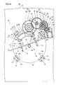
- the display screen turning apparatus 20 is constituted of a turning portion 30 for turning the display body 10 (see Fig. 2) in the direction A or B, a horizontal turn driving portion 40, formed by a plurality of gears etc. described later, provided for horizontally turning (rotating) a discoidal turntable 31 described later and a display screen support mechanism 50 provided on the turntable 31 for supporting the display body 10, as shown in Fig. 3.
- the display screen support mechanism 50 is an example of the "support member" in the present invention.
- the turning portion 30 is constituted of the discoidal turntable 31 of sheet metal mounted with the display screen support mechanism 50 (see Fig. 2), 24 steel balls 32 arranged in through-holes 33a (see Fig. 5) of a holding member 33 described later, the holding member 33 of resin rotatably holding the steel balls 32, a base member 34 of sheet metal and floating prevention members 35 (four in this embodiment) of metal, as shown in Figs. 4 and 5.
- the turntable 31 and the steel balls 32 are examples of the "support member” and the "rolling elements” in the present invention respectively.
- a hole 31b receiving a rotating shaft portion 341 described later is formed at the center of the discoidal turntable 31 of sheet metal, as shown in Fig. 5.
- the holding member 33 of resin is annularly formed in plan view, as shown in Fig. 5.
- This holding member 33 is provided with the 24 through-holes 33a substantially rectangular (substantially square in this embodiment) in plan view at a prescribed interval.
- the holding member 33 has a height (vertical thickness) smaller than the diameter of the steel balls 32 and a diameter substantially equal to that of the outer peripheral surface 31a of the turntable 31. Therefore, the plurality of steel balls 32 charged into the through-holes 33a (see Fig. 5) of the holding member 33 are held between the turntable 31 and the base 34 from above and from below respectively as shown in Fig. 4, so that the turntable 31 is rotatable in the direction A or B on the base 34.
- the platelike base member 34 has a substantially trapezoidal shape in plan view, and is so formed as to receive the load of the display body 10 (see Fig. 1) applied to the display screen support mechanism 50 and the turntable 31 through the 24 steel balls 32 stored in the holding member 33, as shown in Figs. 4 and 5.
- the base member 34 has a side 34a extending substantially in the cross direction of the display body 10 on the front side of the display body 10, sides 34b extending from both ends of the side 34a in directions intersecting with the side 34a and a side 34c coupling the sides 34b with each other at the back of the display body 10.
- the side 34a and the sides 34c are examples of the "upper side” and the "lower side” in the present invention respectively.
- the base member 34 is so formed that the maximum length L2 in the anteroposterior direction (direction X in Fig. 7) of the display body 10 is smaller than the maximum length L1 in the cross direction (direction Y in Fig. 7) of the display body 10, as shown in Fig. 7.
- the base member 34 is longer in the cross direction (direction Y in Fig. 7) of the display body 10, and shorter in the anteroposterior direction of the display body 10 and the direction (direction X in Fig. 7) perpendicular to the side 34a or the sides 34c.
- the base member 34 is so formed as to warp along arrow Z1 (in a direction opposite to the direction of deflection (downward direction) resulting from the load of the display body 10) with a prescribed amount of warpage (about 0.5 mm in this embodiment) in the direction X (short-side direction) when not receiving the load of the display body 10 before the liquid crystal television 100 is placed on a stand 200.
- the prescribed amount of warpage of the base member 34 is so set that the base member 34 is substantially flattened when receiving the load of the display body 10 after the liquid crystal television 100 is placed on the stand 200, as shown in Fig. 12.
- the base member 34 is provided with four projecting portions 34d for mounting the floating prevention members 35, six projecting portions 34e for mounting a cover member 21 (see Fig. 1) described later on the base member 34 and an opening 34f (see Fig. 8) in which the rotating shaft portion 341 described later is arranged, as shown in Figs. 4 and 5.
- the projecting portions 34d and 34e are formed by press working to have drawn shapes protruding upward (toward the turntable 31).
- the projecting portions 34d are elliptic in plan view, and formed at an equiangular interval (interval of 90° according to this embodiment), to enclose the outer peripheral surface 31a of the turntable 31 and the holding member 33.
- the projecting portions 34d are provided with pairs of screw mounting holes 34g for mounting the floating prevention members 35.
- the projecting portions 34e also elliptic in plan view, are provided by threes in the vicinity of the side 34a and the side 34c respectively. Screw receiving holes 34h for mounting the cover member 21 are formed on the projecting portions 34e.
- the opening 34f of the base member 34 is provided at the center of the base member 34.
- the rotating shaft portion 341 of metal is mounted on the center of the base member 34 by caulking, to protrude upward (toward the turntable 31) from the bottom surface of the base member 34 through the opening 34f, as shown in Fig. 8.
- a groove portion 341a for mounting an E-ring 36 is formed on the outer peripheral surface of the rotating shaft portion 341 in the vicinity of the upper end along the circumferential direction, as shown in Fig. 5.
- the E-ring 36 is an example of the "stop member" in the present invention. As shown in Fig. 4, the E-ring 36 is fitted with the groove portion 341a (see Fig.
- six rubber legs 342a and 342b having a thickness of about 2.5 mm are mounted on the bottom surface of the base member 34 with an adhesive, as shown in Fig. 7.
- Four (rubber legs 342b) of these six rubber legs 342a and 342b are provided under the projecting portions 34e provided in the vicinity of four corners located outside the region receiving the load of the display body 10.
- the remaining two (rubber legs 342a) of the six rubber legs 342a and 342b are provided under the region where the steel balls 32 are arranged on the upper surface of the base member 34 respectively.
- the two rubber legs 342a are arranged on a centerline 530 extending in the direction X (short-side direction) of the base member 34 in the region where the steel balls 32 are arranged, on positions separated from each other at a prescribed interval. More specifically, the rubber legs 342a are provided at an equiangular interval of 180°.
- the rubber legs 342a and 342b are examples of the "first rubber leg” and the "second rubber legs” in the present invention respectively.
- the floating prevention members 35 are mounted on the projecting portions 34d by screws 70 fastened to the screw receiving holes 34g provided on the projecting portions 34d through screw receiving holes 35a provided on the floating prevention members 35, as shown in Figs. 5 and 6. As shown in Fig. 6, each floating prevention member 35 is so formed that a floating prevention portion 35b thereof inhibits the turntable 31 from vertical movement while a leg portion 35c thereof positions the turntable 31 and the holding member 33 in a horizontal plane when the turntable 31 rotates in the direction A or B (see Fig. 4).
- the horizontal turn driving portion 40 is constituted of a transmission gear portion 41 for rotating the turntable 31 provided on the base member 34 along the direction A or B in the horizontal plane and a stepping motor 42 serving as a driving source for the transmission gear portion 41, as shown in Fig. 3.
- the horizontal turn driving portion 40 is arranged on the base member 34.
- the transmission gear portion 41 is constituted of a gear 43 of resin, a torque limiter 60 and another gear 44 of resin all arranged in a gear box 46 of resin and still another gear 45 of resin.
- a worm gear 47 of resin is press-fitted into the rotating shaft of the stepping motor 42, as shown in Fig. 9.
- the gear 43 integrally includes a large-diametral gear portion 43a and a small-diametral gear portion 43b, as shown in Figs. 9 and 10.
- the gear 44 also integrally includes a large-diametral gear portion 44a and a small-diametral gear portion 44b.
- the gear 45 integrally includes a large-diametral gear portion 45a and a small-diametral gear portion 45b (see Fig. 10).
- a turning gear member 48 of resin is fixed to the upper surface of the turntable 31 of the turning portion 30 with four screws 70, as shown in Figs. 3, 4 and 9.
- This turning gear member 48 is so formed as to turn in a prescribed angular range ( ⁇ 30° according to this embodiment) through a stopper member (not shown) coming into contact therewith when the turning angle of the turntable 31 reaches a prescribed level.
- Fig. 9 omits the stepping motor 42 and the gear box 46 storing the gear 43, the torque limiter 60 and the gear 44, in order to illustrate the structure of the transmission gear portion 41.
- the worm gear 47 meshes with the large-diametral gear portion 43a of the gear 43 so that the rotating shafts thereof are perpendicular to each other, while the small-diametral gear portion 43b of the gear 43 meshes with a gear portion 62a of a driving gear 62 of the torque limiter 60 so that the rotating shafts thereof are parallel to each other.
- a gear portion 61a of a driven gear 61 of the torque limiter 60 meshes with the large-diametral gear portion 44a of the gear 44 so that the rotating shafts thereof are parallel to each other, while the small-diametral gear portion 44b of the gear 44 meshes with the large-diametral gear portion 45a of the gear 45 so that the rotating shafts thereof are parallel to each other. Therefore, the driving force of the stepping motor 42 is transmitted to the turntable 31 through the worm gear 47, the gear 43, the torque limiter 60, the gears 44, 45 and the turning gear member 48, due to the aforementioned arrangement of these gears shown in Figs. 9 and 10.
- the torque limiter 60 is constituted of the driven gear 61 of resin, the driving gear 62 of resin and a spring member (coil spring) 63 of metal, as shown in Figs. 9 and 10.
- This torque limiter 60 has a function of preventing the rotating stepping motor 42 from application of a load by cutting off the driving force transmitted from the stepping motor 42 to the turntable 31 between the driven gear 61 and the driving gear 62 when the turntable 31 turning by the driving force of the stepping motor 42 comes into contact with the stopper member (not shown) to stop turning.
- the display screen support mechanism 50 is provided on the upper surface of the turntable 31, as shown in Fig. 3.
- the display screen support mechanism 50 is constituted of a display screen support member 51 and a reinforcing member 52 for reinforcing the display screen support member 51.
- the display screen support member 51 and the reinforcing member 52 are fixed to the turntable 31 with two screws 70, to extend perpendicularly to the surface of the turntable 31.
- the display screen support member 51 is provided adjacently to the reinforcing member 52, and coupled to the reinforcing member 52 with three screws 70.
- the display body 10 is constituted of a front cabinet 11 of resin and a rear cabinet 12 of resin, as shown in Figs. 1 and 2.
- a liquid crystal module (not shown) mounted with a liquid crystal panel (not shown) is enclosed with the front cabinet 11 and the rear cabinet 12.
- the display body 10 is mounted on the display screen support member 51 by screws 70 fastened to screw mounting holes (not shown) through screw receiving holes 51a and 51b (see Fig. 2) of the display screen support member 51.
- the rear cabinet 12 is integrally provided with a notch 12a for arranging the display screen support member 51 in a concealed manner.
- a plurality of screw receiving holes 12b (seven in this embodiment) are provided on the outer periphery of the rear cabinet 12, so that the rear cabinet 12 is mounted on the front cabinet 11 with screws 80.
- the cover member 21 and another cover member 22 of resin are mounted on the display screen turning apparatus 20, as shown in Figs. 1 and 2. More specifically, the cover member 21 is mounted on the base member 34 by screws 70 (see Fig. 12) mounted from below the bottom surface of the base member 34 through the screw receiving holes 34h (see Fig. 4).
- the cover member 22 is so provided as to cover the upper portion of the turntable 31 (see Fig. 3) and to be turnable in the direction A or B along with the turntable 31.
- the cover member 22 of resin is provided with a receiving hole 22a for receiving the display screen support mechanism 50.
- the user presses an automatic turning button (not shown) of an attached remote controller (not shown), so that a signal for turning the display body 10 (see Fig. 1) in the direction A is transmitted to a control circuit portion (not shown) of the display body 10.
- the stepping motor 42 of the display screen turning apparatus 20 is driven on the basis of this signal. More specifically, the stepping motor 42 is so driven that the worm gear 47 mounted thereon rotates in a direction E1 (see Fig. 9), as shown in Fig. 3.
- the gear 43 rotates in a direction E2
- the driving gear 62 and the driven gear 61 of the torque limiter 60 rotate in a direction E3
- the gear 44 rotates in a direction E4
- the gear 45 rotates in a direction E5
- the turning gear member 48 rotates in the direction A. Therefore, the turntable 31 mounted with the display screen support member 51 starts turning in the direction A, whereby the display body 10 (see Fig. 1) also starts turning in the direction A.
- the turntable 31 receiving the display body 10 (see Fig. 1) thereon continuously turns in the direction A at a prescribed rotational speed.
- the floating prevention portions 35b and the leg portions 35c of the four floating prevention members 35 prevent backlash in the axial direction of the rotating shaft portion 341 of the turntable 31 and in the direction perpendicular thereto, so that the turntable 31 is turnable.
- the user releases the automatic turning button (not shown) of the attached remote controller (not shown), so that the signal for turning the display body 10 (see Fig. 1) in the direction A is not transmitted to the control circuit portion (not shown) of the display body 10. Therefore, the stepping motor 42 is stopped.
- the turntable 31 stops turning in the direction A on the position shown in Fig. 13, and comes to a standstill.
- the turning angle of the turntable 31 reaches the maximum (30° in this embodiment) while the user continuously turns the display body 10 (see Fig. 1) in the direction A (see Fig. 1), the turntable 31 comes into contact with the stopper member (not shown) provided in the turning portion 30, to be prevented from further turning in the direction A (see Fig. 1). Therefore, the turntable 31 stops turning in the direction A on the position shown in Fig. 14, and comes to a standstill. At this time, the stepping motor 42 is still continuously driven as shown in Fig. 14. Therefore, the torque limiter 60 cuts off the driving force from the stepping motor 42 between the driving gear 62 and the driven gear 61, thereby preventing the rotating stepping motor 42 from application of a load.
- the stepping motor 42 is oppositely driven in order to turn the turntable 31 in the direction B opposite to the direction A, thereby turning the turntable 31 in the direction B.
- the platelike base member 34 is so formed as to warp along arrow Z1 (in the direction opposite to the direction of deflection resulting from the load of the display body 10) with the prescribed amount of warpage (about 0.5 mm in this embodiment) when not receiving the load of the display body 10, whereby the base member 34 warps along arrow Z2 (see Fig. 12) by receiving the load of the display body 10 when the liquid crystal television 100 is placed on the stand 200.
- the warping of the base member 34 along arrow Z1 is canceled, whereby the base member 34 can be substantially flattened. Therefore, the base member 34 can support the turntable 31 in the substantially flat state, thereby stably supporting the display body 10.
- the turntable 31 can be prevented from difficulty in rotation resulting from deflection of the base member 34 along arrow Z2 (see Fig. 12), to be smoothly rotatable.
- the prescribed amount of warpage is so set that the base member 34 is substantially flattened when receiving the load of the display body 10, whereby the base member 34 can be easily substantially flattened when deflected along arrow Z2 (see Fig. 12) due to the load of the display body 10 of the liquid crystal television 100 placed on the stand 200.
- the base member 34 may have a substantially trapezoidal shape in plan view, and may be so formed as to warp along the direction perpendicular to the side 34a or 34c of the trapezoidal shape in plan view.
- the base member 34 is so formed that the maximum length L2 in the anteroposterior direction (direction X in Fig. 7) of the display body 10 is smaller than the maximum length L1 in the cross direction (direction Y in Fig. 7) of the display body 10 and so formed as to warp along the anteroposterior direction (direction X in Fig. 7) of the display body 10 so that the base member 34 warps along the short-side direction (direction X in Fig. 7) thereof, whereby the magnitude of bending moment applied to the base member 34 due to the load of the display body 10 can be reduced as compared with a case where the base member 34 warps along the longitudinal direction (direction Y in Fig. 7) thereof.
- the deflection along arrow Z2 (see Fig. 12) resulting from the load of the display body 10 can be canceled with a small amount of warpage.
- the rubber legs 342a are provided under the region of the base member 34 receiving the load of the display body 10 so that the rubber legs 342a can support the region of the base member 34 receiving the load of the display body 10 while the aforementioned warping of the base member 34 is canceled and the platelike base member 34 is substantially flattened when deflected along arrow Z2 (see Fig. 12) due to the load of the display body 10, whereby the base member 34 can be inhibited from downward deflection (along arrow Z2 in Fig. 12) not only by reaction force resulting from the aforementioned warping of the platelike base member 34 but also by the rubber legs 342a after the platelike base member 34 is substantially flattened.
- the platelike base member 34 can be maintained in the flat state.
- the display screen turning apparatus 20 is provided with the 24 steel balls 32 annularly arranged between the turntable 31 and the base member 34 for receiving the load of the display body 10 through the display screen support mechanism 50 and the turntable 31 and the annular holding member 31 holding the 24 steel balls 32 and having the annular shape while the rubber legs 342a are arranged under the region of the base member 34 corresponding to the steel balls 32 so that the rubber legs 342a can be easily arranged under the region of the base member 34 receiving the load of the display body 10, whereby the rubber legs 342a can easily support the region of the base member 34 receiving the load of the display body 10 while the aforementioned warping of the base member 34 is canceled and the platelike base member 34 is substantially flattened when deflected along arrow Z2 (see Fig.
- the base member 34 can be inhibited from downward deflection (along arrow Z2 in Fig. 12) not only by reaction force resulting from the aforementioned warping of the platelike base member 34 but also by the rubber legs 342a, whereby the platelike base member 34 can be easily maintained in the flat state. Therefore, the steel balls 32 can be prevented from difficulty in rotation resulting from deflection of the base member 34, whereby the steel balls 32 held by the holding member 33 can smoothly rotate on the base member 34.
- the rubber legs 342a are provided on the region of the base member 34 corresponding to the steel balls 32 at the equiangular interval, whereby the rubber legs 342a provided on the base member 34 at the equiangular interval can uniformly receive the load of the base member 34.
- the base member 34 can be more stably supported.
- the display screen turning apparatus 20 further comprises the rubber legs 342b provided under the portions in the vicinity of the four corners located outside the region of the base member 34 receiving the load of the display body 10 so that the rubber legs 342b provided in the vicinity of the four corners of the base member 34 can support the overall base member 34, whereby the base member 34 can be more stably supported.
- the display screen turning apparatus 20 further comprises the rotating shaft portion 341 provided at the center of the base member 34 to protrude toward the turntable 31 for serving as the rotation center of the turntable 31, whereby the turntable 31 can easily rotate about the rotating shaft portion 341.
- the turntable 31 is horizontally rotatable about the rotating shaft portion 341 serving as the rotation center
- the display screen turning apparatus 20 further comprises the E-ring 36 for preventing the turntable 31 from slipping off the rotating shaft portion 341
- the groove portion 341a for mounting the E-ring 36 is provided on the outer peripheral surface of the rotating shaft portion 341 in the vicinity of the upper end, whereby the turntable 31 can be inhibited from slipping off the rotating shaft portion 341.
- the base member 34 is made of sheet metal, whereby the base member 34 can be easily warped when the same is manufactured.
- the display screen turning apparatus 20 is provided on the liquid crystal television 10 employed as an exemplary display in the aforementioned embodiment, the present invention is not restricted to this but the display screen turning apparatus 20 may alternatively be provided on a display such as an EL panel having a display screen (display panel) other than the liquid crystal panel.
- rotatable turntable 31 and the rotatable display screen support mechanism 50 are employed in the aforementioned embodiment as examples of the support member, the present invention is not restricted to this but an unrotative support member may alternatively be employed.
- base member 34 having a substantially trapezoidal shape in plan view is employed in the aforementioned embodiment, the present invention is not restricted to this but a base member having a substantially rectangular or circular shape in plan view may alternatively be employed.
- the base member 34 is so formed as to warp along arrow Z1 in the anteroposterior direction (direction X) of the display body 10 with the prescribed amount of warpage in the aforementioned embodiment, the present invention is not restricted to this the base member 34 may alternatively warp to upwardly protrude in the form of a semicircle having the top at the center.
Landscapes
- Engineering & Computer Science (AREA)
- General Engineering & Computer Science (AREA)
- Mechanical Engineering (AREA)
- Devices For Indicating Variable Information By Combining Individual Elements (AREA)
Applications Claiming Priority (1)
| Application Number | Priority Date | Filing Date | Title |
|---|---|---|---|
| JP2006009272U JP3128969U (ja) | 2006-11-14 | 2006-11-14 | 表示画面用台座 |
Publications (3)
| Publication Number | Publication Date |
|---|---|
| EP1923616A2 true EP1923616A2 (fr) | 2008-05-21 |
| EP1923616A3 EP1923616A3 (fr) | 2010-11-03 |
| EP1923616B1 EP1923616B1 (fr) | 2012-04-04 |
Family
ID=39033677
Family Applications (1)
| Application Number | Title | Priority Date | Filing Date |
|---|---|---|---|
| EP07254400A Not-in-force EP1923616B1 (fr) | 2006-11-14 | 2007-11-07 | Base pour écran de visualisation |
Country Status (3)
| Country | Link |
|---|---|
| US (1) | US8368821B2 (fr) |
| EP (1) | EP1923616B1 (fr) |
| JP (1) | JP3128969U (fr) |
Cited By (1)
| Publication number | Priority date | Publication date | Assignee | Title |
|---|---|---|---|---|
| CN101635812B (zh) * | 2008-07-23 | 2011-09-21 | 厦门华侨电子股份有限公司 | 一种平板电视机底座支架与整机之间的连接结构 |
Families Citing this family (6)
| Publication number | Priority date | Publication date | Assignee | Title |
|---|---|---|---|---|
| JP5200435B2 (ja) * | 2007-07-06 | 2013-06-05 | 船井電機株式会社 | 表示画面旋回装置 |
| CN101888800A (zh) * | 2007-10-12 | 2010-11-17 | 爱格升公司 | 可变换的显示器台座系统和方法 |
| JP5508673B2 (ja) * | 2007-12-27 | 2014-06-04 | 株式会社東芝 | 表示装置 |
| CN108071913A (zh) * | 2016-11-10 | 2018-05-25 | 深圳市炫硕智造技术有限公司 | 显示屏支架结构及编带机 |
| US11086369B2 (en) * | 2019-04-16 | 2021-08-10 | Microsoft Technology Licensing, Llc | Display rotation locking mechanism |
| TW202124871A (zh) * | 2019-12-17 | 2021-07-01 | 香港商冠捷投資有限公司 | 顯示裝置 |
Citations (3)
| Publication number | Priority date | Publication date | Assignee | Title |
|---|---|---|---|---|
| JPS61185946A (ja) | 1985-02-13 | 1986-08-19 | Mitsubishi Electric Corp | 半導体素子用樹脂封止装置 |
| JP2004314466A (ja) | 2003-04-17 | 2004-11-11 | Dainippon Toryo Co Ltd | 化粧板の製造方法 |
| JP2006126544A (ja) | 2004-10-29 | 2006-05-18 | Toppan Printing Co Ltd | 背面投影型ディスプレイ用光学部材及びその製造方法及び背面投影型ディスプレイ |
Family Cites Families (14)
| Publication number | Priority date | Publication date | Assignee | Title |
|---|---|---|---|---|
| US2895770A (en) * | 1956-01-09 | 1959-07-21 | Wil Mat Corp | Swivel bearing |
| US5164203A (en) | 1985-02-13 | 1992-11-17 | Mitsubishi Denki Kabushiki Kaisha | Plastic molding device for a semiconductor element |
| US4755124A (en) | 1985-02-13 | 1988-07-05 | Mitsubishi Denki Kabushiki Kaisha | Plastic molding device for a semiconductor element |
| US5243434A (en) * | 1990-06-29 | 1993-09-07 | Mitsubishi Denki Kabushiki Kaisha | Swivel device for a television receiver |
| KR100224302B1 (ko) * | 1997-01-10 | 1999-10-15 | 윤종용 | 화면디스플레이 각도 조절이 원활한 디스플레이모니터의 스탠드 |
| US5934640A (en) * | 1997-02-06 | 1999-08-10 | Hall; Tracy R. | Device for mounting and adjusting a video-phone and methods thereof |
| US5964437A (en) * | 1997-10-27 | 1999-10-12 | Belokin; Paul | Mounting support |
| JP2002311845A (ja) * | 2001-04-16 | 2002-10-25 | Fujitsu Ltd | 表示装置 |
| JP3106184U (ja) * | 2004-06-25 | 2004-12-16 | 船井電機株式会社 | 液晶テレビジョンおよび液晶表示装置 |
| JP2006243568A (ja) * | 2005-03-07 | 2006-09-14 | Sharp Corp | スタンド装置 |
| JP4169044B2 (ja) * | 2006-04-27 | 2008-10-22 | 船井電機株式会社 | 回動装置及び回動装置を備えた映像表示装置 |
| JP4179371B2 (ja) * | 2006-10-27 | 2008-11-12 | 船井電機株式会社 | 表示画面旋回装置 |
| JP4222410B2 (ja) * | 2006-11-07 | 2009-02-12 | 船井電機株式会社 | 表示画面旋回装置 |
| JP2009284131A (ja) * | 2008-05-21 | 2009-12-03 | Funai Electric Co Ltd | 表示装置およびテレビジョン装置 |
-
2006
- 2006-11-14 JP JP2006009272U patent/JP3128969U/ja not_active Expired - Fee Related
-
2007
- 2007-11-07 EP EP07254400A patent/EP1923616B1/fr not_active Not-in-force
- 2007-11-13 US US11/939,285 patent/US8368821B2/en not_active Expired - Fee Related
Patent Citations (3)
| Publication number | Priority date | Publication date | Assignee | Title |
|---|---|---|---|---|
| JPS61185946A (ja) | 1985-02-13 | 1986-08-19 | Mitsubishi Electric Corp | 半導体素子用樹脂封止装置 |
| JP2004314466A (ja) | 2003-04-17 | 2004-11-11 | Dainippon Toryo Co Ltd | 化粧板の製造方法 |
| JP2006126544A (ja) | 2004-10-29 | 2006-05-18 | Toppan Printing Co Ltd | 背面投影型ディスプレイ用光学部材及びその製造方法及び背面投影型ディスプレイ |
Cited By (1)
| Publication number | Priority date | Publication date | Assignee | Title |
|---|---|---|---|---|
| CN101635812B (zh) * | 2008-07-23 | 2011-09-21 | 厦门华侨电子股份有限公司 | 一种平板电视机底座支架与整机之间的连接结构 |
Also Published As
| Publication number | Publication date |
|---|---|
| EP1923616A3 (fr) | 2010-11-03 |
| US20080111928A1 (en) | 2008-05-15 |
| US8368821B2 (en) | 2013-02-05 |
| EP1923616B1 (fr) | 2012-04-04 |
| JP3128969U (ja) | 2007-02-01 |
Similar Documents
| Publication | Publication Date | Title |
|---|---|---|
| EP1923616B1 (fr) | Base pour écran de visualisation | |
| EP1923617B1 (fr) | Appareil de rotation d'écran de visualisation | |
| EP2116754B1 (fr) | Dispositif de rotation d'écran d'affichage | |
| EP1921367B1 (fr) | Appareil de rotation d'écran de visualisation | |
| EP2112419B1 (fr) | Appareil de rotation d'écran d'affichage | |
| JP3128969U7 (fr) | ||
| JP4254870B2 (ja) | 表示画面旋回装置 | |
| US8157237B2 (en) | Display screen turning apparatus | |
| EP1916466B1 (fr) | Appareil de rotation d'écran de visualisation | |
| EP2123966A2 (fr) | Dispositif d'affichage | |
| US8120715B2 (en) | Torque limiter, display screen turning apparatus comprising torque limiter and television set including torque limiter | |
| EP2608237A1 (fr) | Ensemble de touches, panneau de commande et appareil de formation d'image | |
| JP5200435B2 (ja) | 表示画面旋回装置 | |
| JP3128966U (ja) | 表示画面旋回装置 | |
| JP3128971U (ja) | 表示画面旋回装置 | |
| JP3128971U7 (fr) | ||
| CN211260150U (zh) | 显示装置 | |
| JP6985835B2 (ja) | スタンド、およびテレビジョン装置 | |
| KR20040021740A (ko) | 영상표시기기의 회전받침 구조 | |
| JP2012018251A (ja) | ヒンジ装置 |
Legal Events
| Date | Code | Title | Description |
|---|---|---|---|
| PUAI | Public reference made under article 153(3) epc to a published international application that has entered the european phase |
Free format text: ORIGINAL CODE: 0009012 |
|
| AK | Designated contracting states |
Kind code of ref document: A2 Designated state(s): AT BE BG CH CY CZ DE DK EE ES FI FR GB GR HU IE IS IT LI LT LU LV MC MT NL PL PT RO SE SI SK TR |
|
| AX | Request for extension of the european patent |
Extension state: AL BA HR MK RS |
|
| PUAL | Search report despatched |
Free format text: ORIGINAL CODE: 0009013 |
|
| AK | Designated contracting states |
Kind code of ref document: A3 Designated state(s): AT BE BG CH CY CZ DE DK EE ES FI FR GB GR HU IE IS IT LI LT LU LV MC MT NL PL PT RO SE SI SK TR |
|
| AX | Request for extension of the european patent |
Extension state: AL BA HR MK RS |
|
| 17P | Request for examination filed |
Effective date: 20110427 |
|
| AKX | Designation fees paid |
Designated state(s): DE FR GB PL |
|
| GRAP | Despatch of communication of intention to grant a patent |
Free format text: ORIGINAL CODE: EPIDOSNIGR1 |
|
| RBV | Designated contracting states (corrected) |
Designated state(s): DE FR GB |
|
| GRAS | Grant fee paid |
Free format text: ORIGINAL CODE: EPIDOSNIGR3 |
|
| GRAA | (expected) grant |
Free format text: ORIGINAL CODE: 0009210 |
|
| AK | Designated contracting states |
Kind code of ref document: B1 Designated state(s): DE FR GB |
|
| REG | Reference to a national code |
Ref country code: GB Ref legal event code: FG4D |
|
| REG | Reference to a national code |
Ref country code: DE Ref legal event code: R096 Ref document number: 602007021729 Country of ref document: DE Effective date: 20120531 |
|
| PLBE | No opposition filed within time limit |
Free format text: ORIGINAL CODE: 0009261 |
|
| STAA | Information on the status of an ep patent application or granted ep patent |
Free format text: STATUS: NO OPPOSITION FILED WITHIN TIME LIMIT |
|
| 26N | No opposition filed |
Effective date: 20130107 |
|
| REG | Reference to a national code |
Ref country code: DE Ref legal event code: R097 Ref document number: 602007021729 Country of ref document: DE Effective date: 20130107 |
|
| REG | Reference to a national code |
Ref country code: FR Ref legal event code: PLFP Year of fee payment: 9 |
|
| PGFP | Annual fee paid to national office [announced via postgrant information from national office to epo] |
Ref country code: GB Payment date: 20151104 Year of fee payment: 9 Ref country code: DE Payment date: 20151103 Year of fee payment: 9 |
|
| PGFP | Annual fee paid to national office [announced via postgrant information from national office to epo] |
Ref country code: FR Payment date: 20151008 Year of fee payment: 9 |
|
| REG | Reference to a national code |
Ref country code: DE Ref legal event code: R119 Ref document number: 602007021729 Country of ref document: DE |
|
| GBPC | Gb: european patent ceased through non-payment of renewal fee |
Effective date: 20161107 |
|
| REG | Reference to a national code |
Ref country code: FR Ref legal event code: ST Effective date: 20170731 |
|
| PG25 | Lapsed in a contracting state [announced via postgrant information from national office to epo] |
Ref country code: FR Free format text: LAPSE BECAUSE OF NON-PAYMENT OF DUE FEES Effective date: 20161130 |
|
| PG25 | Lapsed in a contracting state [announced via postgrant information from national office to epo] |
Ref country code: DE Free format text: LAPSE BECAUSE OF NON-PAYMENT OF DUE FEES Effective date: 20170601 Ref country code: GB Free format text: LAPSE BECAUSE OF NON-PAYMENT OF DUE FEES Effective date: 20161107 |