EP1920853A2 - Vorrichtung zum Behandeln von Werkstücken oder dergleichen - Google Patents
Vorrichtung zum Behandeln von Werkstücken oder dergleichen Download PDFInfo
- Publication number
- EP1920853A2 EP1920853A2 EP07021618A EP07021618A EP1920853A2 EP 1920853 A2 EP1920853 A2 EP 1920853A2 EP 07021618 A EP07021618 A EP 07021618A EP 07021618 A EP07021618 A EP 07021618A EP 1920853 A2 EP1920853 A2 EP 1920853A2
- Authority
- EP
- European Patent Office
- Prior art keywords
- drum
- workpieces
- tube
- liquid
- filling
- Prior art date
- Legal status (The legal status is an assumption and is not a legal conclusion. Google has not performed a legal analysis and makes no representation as to the accuracy of the status listed.)
- Granted
Links
- 238000003754 machining Methods 0.000 title 1
- 238000004140 cleaning Methods 0.000 claims abstract description 18
- 238000001035 drying Methods 0.000 claims abstract description 10
- 239000007788 liquid Substances 0.000 claims description 33
- XLYOFNOQVPJJNP-UHFFFAOYSA-N water Substances O XLYOFNOQVPJJNP-UHFFFAOYSA-N 0.000 claims description 10
- 239000012530 fluid Substances 0.000 abstract description 2
- 238000005406 washing Methods 0.000 description 4
- 239000000356 contaminant Substances 0.000 description 3
- 230000000694 effects Effects 0.000 description 3
- 238000004519 manufacturing process Methods 0.000 description 3
- 239000000126 substance Substances 0.000 description 3
- 206010013786 Dry skin Diseases 0.000 description 1
- 229920005372 Plexiglas® Polymers 0.000 description 1
- 239000000654 additive Substances 0.000 description 1
- 230000002238 attenuated effect Effects 0.000 description 1
- 238000011109 contamination Methods 0.000 description 1
- 230000008878 coupling Effects 0.000 description 1
- 238000010168 coupling process Methods 0.000 description 1
- 238000005859 coupling reaction Methods 0.000 description 1
- 239000000945 filler Substances 0.000 description 1
- 238000011010 flushing procedure Methods 0.000 description 1
- 238000002347 injection Methods 0.000 description 1
- 239000007924 injection Substances 0.000 description 1
- 239000000463 material Substances 0.000 description 1
- 239000002184 metal Substances 0.000 description 1
- 239000004033 plastic Substances 0.000 description 1
- 229920003023 plastic Polymers 0.000 description 1
- 239000004926 polymethyl methacrylate Substances 0.000 description 1
- 230000001681 protective effect Effects 0.000 description 1
- 239000000243 solution Substances 0.000 description 1
- 239000012780 transparent material Substances 0.000 description 1
Images


Classifications
-
- B—PERFORMING OPERATIONS; TRANSPORTING
- B08—CLEANING
- B08B—CLEANING IN GENERAL; PREVENTION OF FOULING IN GENERAL
- B08B3/00—Cleaning by methods involving the use or presence of liquid or steam
- B08B3/04—Cleaning involving contact with liquid
- B08B3/041—Cleaning travelling work
- B08B3/042—Cleaning travelling work the loose articles or bulk material travelling gradually through a drum or other container, e.g. by helix or gravity
-
- B—PERFORMING OPERATIONS; TRANSPORTING
- B08—CLEANING
- B08B—CLEANING IN GENERAL; PREVENTION OF FOULING IN GENERAL
- B08B3/00—Cleaning by methods involving the use or presence of liquid or steam
- B08B3/04—Cleaning involving contact with liquid
- B08B3/06—Cleaning involving contact with liquid using perforated drums in which the article or material is placed
-
- F—MECHANICAL ENGINEERING; LIGHTING; HEATING; WEAPONS; BLASTING
- F26—DRYING
- F26B—DRYING SOLID MATERIALS OR OBJECTS BY REMOVING LIQUID THEREFROM
- F26B11/00—Machines or apparatus for drying solid materials or objects with movement which is non-progressive
- F26B11/02—Machines or apparatus for drying solid materials or objects with movement which is non-progressive in moving drums or other mainly-closed receptacles
- F26B11/028—Arrangements for the supply or exhaust of gaseous drying medium for direct heat transfer, e.g. perforated tubes, annular passages, burner arrangements, dust separation, combined direct and indirect heating
-
- F—MECHANICAL ENGINEERING; LIGHTING; HEATING; WEAPONS; BLASTING
- F26—DRYING
- F26B—DRYING SOLID MATERIALS OR OBJECTS BY REMOVING LIQUID THEREFROM
- F26B11/00—Machines or apparatus for drying solid materials or objects with movement which is non-progressive
- F26B11/02—Machines or apparatus for drying solid materials or objects with movement which is non-progressive in moving drums or other mainly-closed receptacles
- F26B11/04—Machines or apparatus for drying solid materials or objects with movement which is non-progressive in moving drums or other mainly-closed receptacles rotating about a horizontal or slightly-inclined axis
- F26B11/0436—Machines or apparatus for drying solid materials or objects with movement which is non-progressive in moving drums or other mainly-closed receptacles rotating about a horizontal or slightly-inclined axis comprising multiple stages, e.g. multiple rotating drums subsequently receiving the material to be dried; Provisions for heat recuperation
-
- F—MECHANICAL ENGINEERING; LIGHTING; HEATING; WEAPONS; BLASTING
- F26—DRYING
- F26B—DRYING SOLID MATERIALS OR OBJECTS BY REMOVING LIQUID THEREFROM
- F26B11/00—Machines or apparatus for drying solid materials or objects with movement which is non-progressive
- F26B11/02—Machines or apparatus for drying solid materials or objects with movement which is non-progressive in moving drums or other mainly-closed receptacles
- F26B11/04—Machines or apparatus for drying solid materials or objects with movement which is non-progressive in moving drums or other mainly-closed receptacles rotating about a horizontal or slightly-inclined axis
- F26B11/0463—Machines or apparatus for drying solid materials or objects with movement which is non-progressive in moving drums or other mainly-closed receptacles rotating about a horizontal or slightly-inclined axis having internal elements, e.g. which are being moved or rotated by means other than the rotating drum wall
- F26B11/0477—Machines or apparatus for drying solid materials or objects with movement which is non-progressive in moving drums or other mainly-closed receptacles rotating about a horizontal or slightly-inclined axis having internal elements, e.g. which are being moved or rotated by means other than the rotating drum wall for mixing, stirring or conveying the materials to be dried, e.g. mounted to the wall, rotating with the drum
- F26B11/0481—Machines or apparatus for drying solid materials or objects with movement which is non-progressive in moving drums or other mainly-closed receptacles rotating about a horizontal or slightly-inclined axis having internal elements, e.g. which are being moved or rotated by means other than the rotating drum wall for mixing, stirring or conveying the materials to be dried, e.g. mounted to the wall, rotating with the drum the elements having a screw- or auger-like shape, or form screw- or auger-like channels
Definitions
- the invention relates to a device for treating workpieces or the like, in particular for cleaning and / or drying the workpieces, with a housing in which a conveying means for supplying a medium to the workpieces is arranged.
- the present invention has for its object to provide a device for treating workpieces, in particular for cleaning and / or drying of the workpieces, which is improved over conventional systems.
- the inventive device comprises a rotatable drum of a motor, on the inside of a screw conveyor is fixed, which extends substantially over the entire length of the drum, wherein within the drum in the longitudinal direction at least one nozzle tube extends from the outlet openings of a medium on the Workpieces or the like is directed, and wherein the drum preferably so inclined, ie is arranged at an angle to the horizontal, that it rises in the conveying direction of the workpieces.
- the nozzle tube forms the fixed axis on which the drum rotates, preferably on bearing blocks.
- the device has a filling device, through which the workpieces can be filled in the lower end region of the drum.
- the filling device may be formed by an opening in the housing through which, for example, by means of baskets, the workpieces are filled into the end region of the drum, where they are gripped on rotation of the drum about its longitudinal axis of the screw conveyor and obliquely upwards to the outlet opening the drum to be transported.
- the nozzle tube has at least one axially extending row of holes or nozzles and is adjustable in a preferred embodiment of the invention in the circumferential direction in the desired angular position to direct the media beams to the selected area.
- the nozzle tube may also be adjustable by suitable means in its longitudinal direction.
- the drum can also be fixed, and only the screw conveyor is driven. This is also within the scope of the invention.
- the filling device is formed by a filling chute which allows automatic feeding of the device when the chute is arranged, as is preferred, at the level of ejection of a machine producing or processing the workpieces.
- the workpieces fall in such an arrangement of the device piece for Piece on the drum, wherein a hard impact, for example, by an additionally inserted into the drum, perforated plastic insert can be attenuated.
- a hard impact for example, by an additionally inserted into the drum, perforated plastic insert can be attenuated.
- a water level should be provided in the device in the impact area of the articles that this liquid slows down the parts entering the device via the filling chute so as to prevent a hard impact on the drum is.
- the filling device can also be a driven conveyor belt.
- the transport screw consists of a spiral web which is attached to the drum, for example screwed.
- This spiral ridge has in comparison to the diameter of the drum expediently only a relatively small height in the order of 5 to 10% of the drum diameter.
- a plurality of preferably circular protective disks may be arranged in the drum at an axial distance from each other, which prevent the liquid from spouting out of the device.
- These splashguards are preferably arranged between and after the injection units of the one or more nozzle tubes comprising the nozzle system.
- the drum is made of perforated metal so that cleaning fluid and foreign substances removed from the workpieces can pass through the drum wall.
- the drum is preferably arranged in a substantially trough-shaped non-rotatable return tray, at the bottom of which the liquid flows back.
- annular rack is mounted, which is in engagement with a drive pinion of an electric motor which is mounted on a located outside of the housing end cover of the drum.
- the drum and the trough-shaped return bowl project with its upper end portion out of the housing of the device.
- air or possibly other gas is directed onto the workpieces through the nozzle system by means of a blower housed within the housing or other external or internal source of compressed air.
- a blower housed within the housing or other external or internal source of compressed air.
- a pump is used as conveying means, which is conveniently housed in a chamber separated from a liquid tank in the housing.
- the obliquely increasing arrangement of the drum has the advantage that the liquid ejected from the nozzle system (or the nozzle systems) runs off immediately, whereby the cleaning effect is considerably improved.
- the return shell which in contrast to the drum has a closed wall surface, is arranged with its lower end portion in a Vorfluterhunt, by a preferably provided with openings wall, preferably a cascade wall of the adjacent liquid tank is separated in the housing.
- a filter basket is arranged on the wall provided with openings and / or an overflow, into which the liquid flowing back or falling back from the preflow chamber into the liquid tank enters, whereby the liquid is cleaned of entrained foreign matter.
- a plurality of devices of the type described above be put together to a larger system, which is particularly possible by the inclined position of the drums in a simple manner.
- one or more Washing devices with one or more flushing devices and with one or more drying devices all working on the same system combined.
- the ejected from the feed screw each from the upper outlet opening workpieces fall automatically into the arranged below the filler chute of the next device, from where they get into the beginning of the next drum and are supported by the transport screw again obliquely upwards.
- the device according to the invention can also be used as a single machine, for example for optimum intermediate cleaning between individual processing steps of workpieces or the like.
- the fan used is preferably provided with a heater.
- the liquid in the tank can be heated by a heater.
- the device includes a standing on feet or on lockable rollers housing 1, which is provided with a removable or hinged lid.
- a substantially trough-shaped return tray 10 is fixed, in which a drum 3 is rotatably mounted on bearing blocks 2 about its longitudinal axis on a fixed tube 4.
- the tube 4 has nozzle bores 22 which are arranged on a line extending in the axial direction.
- the return trough 10, which extends beyond the top of the drum 3 and is closed at the top by a removable cover, is inclined, arranged in the illustrated case at an angle of about 30 ° to the horizontal.
- the angle depends on the speed and the size and material of the parts to be cleaned and can be between 5 ° and 45 °.
- a transport screw 14 is fixed, which consists of a spiral web, which has a relatively small height of for example 5 to 10% of the drum diameter compared to the diameter of the drum.
- a filling chute 5 opens through the objects to be cleaned, which are symbolically represented by a hexagon in the drawing, in the lower end of the drum 3, where they are taken by the rotating screw conveyor and gradually to the top End of the drum 3 are transported.
- the articles are sprayed with a pressure exiting from the nozzle tube 4, ie from its symbolically represented nozzles 22, exiting treatment liquid, for example a cleaning liquid, the Remove items from contamination.
- the liquid is supplied to the nozzle tube 4 by a pump 7, which sucks the liquid from a water tank 14a.
- the pump 7 is located in a space 15 separated from the water tank 14a.
- a toothed ring 16 is mounted, which is in engagement with a drive pinion 17 of an electric motor 13, which thus rotates the drum.
- the electric motor 13 is mounted on a cap-shaped cover 12.
- the interior of the drum 3 is divided by a plurality of (in the illustrated case three) evenly spaced splash shields 11, which have a circular shape of such a diameter that they do not hinder the promotion of the objects by the screw conveyor.
- the splashguard expediently consist of a transparent material such as Plexiglas, which is also the case with the frontal splash guard 12 is the case.
- the lower end portion of the return trough 10 and the drum 3 are located in a Vorfluterhunt 19 in the lower housing part 6 above the chamber 15 in which the pump 7 is housed.
- the Vorfluterhunt 19 is separated by a cascade wall 20 of the liquid tank 14 a.
- a filter basket 8 is attached to the cascade wall 20, such that the liquid flowing back from the flooding chamber 19 into the liquid chamber 14a flows into the filter basket 8, where the liquid is freed of entrained foreign matter and contaminants.
- the liquid sprayed from the nozzles onto the articles flows at the bottom of the return trough into the receiving water chamber 19, in which a water level at the upper edge of the wall 20 which is higher than the water level in FIG the liquid tank 14a.
- the water in the Vorfluterhunt 19 flows over the top edge of the wall 20 and optionally through openings in this wall with entrainment of foreign substances in the filter basket, so that in a simple way the contaminants detached from the objects, etc. can be removed from the liquid circuit.
- floating substances such as oil etc. can be removed on the water surface by means of a suitable separating device.
- the drum preferably has a length of about 100 cm to 300 cm and a diameter of about 30 cm to 70 cm.
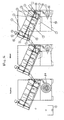
- FIG. 2 shows three successively arranged devices for cleaning, rinsing and drying of objects.
- the device for drying contains only one fan 21 in the lower region of the housing.
- FIG. 3 shows the lower portion of the drum 1 in an enlarged view.
- the nozzle tube 4 is provided at its right end with an external thread on which a hex nut 23 is seated.
- a coupling element By a coupling element, the end of the nozzle tube 4 with a conduit or a hose 24 for supplying the cleaning medium (or the air) is connected.
- the angular position of the nozzle tube 4 is adjustable for adjusting the direction of the medium beams.
- the nozzle tube 4 can also be adjusted in the axial direction.
Landscapes
- Engineering & Computer Science (AREA)
- Mechanical Engineering (AREA)
- General Engineering & Computer Science (AREA)
- Physics & Mathematics (AREA)
- Thermal Sciences (AREA)
- Cleaning By Liquid Or Steam (AREA)
- Feeding Of Workpieces (AREA)
- Heat Treatment Of Strip Materials And Filament Materials (AREA)
- Drying Of Solid Materials (AREA)
Abstract
Description
- Die Erfindung betrifft eine Vorrichtung zum Behandeln von Werkstücken oder dergleichen, insbesondere zum Reinigen und/oder Trocknen der Werkstücke, mit einem Gehäuse, in dem ein Fördermittel zur Zufuhr eines Mediums zu den Werkstücken angeordnet ist.
- In manchen Produktionsbereichen besteht das Problem, dass kleinere Produktionsteile aus automatischen Bearbeitungsmaschinen wie z.B. Pressen oder spanabhebenden Automaten ausgestoßen werden und durch Bearbeitungsstäube oder andere Medien wie z.B. Kühlschmiermittel verunreinigt sind, wobei dies nur einige Beispiele aus einer Vielzahl von Problemfällen sind.
- Zur Reinigung solcher kleiner Werkstücke bzw. Produktionsteile existieren Bandwaschanlagen, die die Teile über ein Band durch eine Durchlaufwaschanlage transportieren. Diese Bandwaschanlagen haben oft nur eine unzufriedenstellende Reinigungsleistung.
- Der vorliegenden Erfindung liegt die Aufgabe zugrunde, eine Vorrichtung zum Behandeln von Werkstücken, insbesondere zum Reinigen und/oder Trocknen der Werkstücke anzugeben, die gegenüber herkömmlichen Anlagen verbessert ist.
- Diese Aufgabe wird erfindungsgemäß durch die Merkmale des Patentanspruchs 1 gelöst.
- Vorteilhafte Ausgestaltungen der Erfindung sind in den Unteransprüchen gekennzeichnet.
- Die erfindungsgemäße Vorrichtung enthält eine von einem Motor drehbare Trommel, an deren Innenseite eine Transportschnecke befestigt ist, die sich im wesentlichen über die gesamte Länge der Trommel erstreckt, wobei innerhalb der Trommel in deren Längsrichtung wenigstens ein Düsenrohr verläuft, aus dessen Austrittsöffnungen ein Medium auf die Werkstücke oder dergleichen gerichtet wird, und wobei die Trommel vorzugsweise derart schräg, d.h. im Winkel zur Horizontalen angeordnet ist, das sie in Förderrichtung der Werkstücke ansteigt. Das Düsenrohr bildet die feststehende Achse, auf der sich die Trommel dreht, und zwar vorzugsweise auf Lagerböcken. Hierdurch ist der Aufbau der Vorrichtung erheblich vereinfacht.
- Die Vorrichtung hat eine Einfülleinrichtung, durch die die Werkstücke in den unteren Endbereich der Trommel einfüllbar sind. In der einfachsten Form kann die Einfülleinrichtung durch eine Öffnung in dem Gehäuse gebildet sein, durch die beispielsweise mittels Körben die Werkstücke in den Endbereich der Trommel eingefüllt werden, wo sie bei Drehung der Trommel um ihre Längsachse von der Transportschnecke ergriffen und schräg nach oben zur Austrittsöffnung der Trommel transportiert werden.
- Das Düsenrohr hat wenigstens eine in axialer Richtung verlaufende Reihe von Löchern oder Düsen und ist in einer bevorzugten Ausgestaltung der Erfindung in Umfangsrichtung in die gewünschte Winkellage einstellbar, um die Mediumstrahlen auf den ausgewählten Bereich zu richten. Das Düsenrohr kann auch durch geeignete Mittel in seiner Längsrichtung verstellbar sein.
- Die Trommel kann aber auch feststehend sein, und nur die Transportschnecke wird angetrieben. Auch dies liegt im Rahmen der Erfindung.
- In einer bevorzugten Ausführungsform ist die Einfülleinrichtung durch eine Einfüllrutsche gebildet, die eine automatische Beschickung der Vorrichtung ermöglicht, wenn die Rutsche - wie dies bevorzugt ist - in Höhe des Auswurfs einer die Werkstücke herstellenden oder bearbeitenden Maschine angeordnet ist. Die Werkstücke fallen bei einer derartigen Anordnung der Vorrichtung Stück für Stück auf die Trommel, wobei ein hartes Aufschlagen beispielsweise durch einen zusätzlich in die Trommel eingelegten, gelochten Kunststoffeinsatz gedämpft werden kann. Wenn die Vorrichtung zum Reinigen von Gegenständen mittels einer Flüssigkeit verwendet wird, sollte im Aufprallbereich der Gegenstände ein solcher Wasserstand in der Vorrichtung vorgesehen sein, dass diese Flüssigkeit die über die Einfüllrutsche in die Vorrichtung einfallenden Teile so abbremst, dass ein harter Aufprall auf die Trommel verhindert ist.
- Die Einfülleinrichtung kann auch ein angetriebenes Förderband sein.
- Weiter wird mit Vorteil vorgeschlagen, dass die Transportschnecke aus einem spiralförmigen Steg besteht, der an der Trommel angebracht, beispielsweise angeschraubt ist. Dieser spiralförmige Steg hat im Vergleich zum Durchmesser der Trommel zweckmäßigerweise nur eine verhältnismäßig geringe Höhe in der Größenordnung von 5 bis 10% des Trommeldurchmessers.
- Insbesondere dann, wenn die Vorrichtung mit einer Flüssigkeit arbeitet, können in der Trommel mehrere vorzugsweise kreisförmige Schutzscheiben im axialen Abstand voneinander angeordnet sein, die ein Herausspritzen der Flüssigkeit aus der Vorrichtung verhindern. Diese Spritzschutzscheiben sind bevorzugt zwischen und nach den Spritzeinheiten des ein oder mehrere Düsenrohre umfassenden Düsensystems angeordnet.
- Weiter ist mit Vorteil vorgesehen, dass die Trommel aus Lochblech besteht, so dass Reinigungsflüssigkeit und von den Werkstücken entfernte Fremdstoffe durch die Trommelwand durchtreten können. Dabei ist die Trommel vorzugsweise in einer im wesentlichen wannenförmigen nicht-drehbaren Rücklaufschale angeordnet, an deren Boden die Flüssigkeit zurückläuft.
- Weiter kann vorgesehen sein, dass auf dem Außenumfang der Trommel, vorzugsweise an deren oberen Endbereich, eine ringförmige Zahnstange befestigt ist, die in Eingriff mit einem Antriebsritzel eines Elektromotors steht, der auf einer außerhalb des Gehäuses befindlichen Endabdeckung der Trommel angebracht ist.
- Dabei ragen die Trommel und die wannenförmige Rücklaufschale mit ihrem oberen Endabschnitt aus dem Gehäuse der Vorrichtung heraus.
- Wenn die Vorrichtung zum Trocknen von Werkstücken oder dergleichen verwendet wird, wird durch das Düsensystem Luft oder gegebenenfalls ein anderes Gas auf die Werkstücke gerichtet, und zwar mittels eines Gebläses, das in dem Gehäuse untergebracht ist oder einer anderen externen oder internen Druckluftquelle. Wenn das Medium eine Flüssigkeit, beispielsweise Wasser mit geeigneten Reinigungszusätzen ist, wird als Fördermittel eine Pumpe verwendet, die zweckmäßigerweise in einer von einem Flüssigkeitstank in dem Gehäuse abgetrennten Kammer untergebracht ist.
- Bei der Verwendung mit einem flüssigen Medium hat die schräg ansteigende Anordnung der Trommel den Vorteil, dass die aus dem Düsensystem (oder den Düsensystemen) ausgespritzte Flüssigkeit sofort wieder abläuft, wodurch die Reinigungswirkung erheblich verbessert wird. In diesem Zusammenhang wird mit großem Vorteil weiter vorgeschlagen, dass die Rücklaufschale, die im Gegensatz zu der Trommel eine geschlossene Wandfläche hat, mit ihrem unteren Endabschnitt in einer Vorfluterkammer angeordnet ist, die durch eine bevorzugt mit Durchbrüchen versehene Wand, vorzugsweise eine Kaskadenwand, von dem daneben liegenden Flüssigkeitstank in dem Gehäuse getrennt ist. Auf der Seite des Flüssigkeitstanks ist an der mit Durchbrüchen und/oder einem Überlauf versehenen Wand ein Filterkorb angeordnet, in den die aus der Vorfluterkammer in den Flüssigkeitstank zurückströmende bzw. zurückfallende Flüssigkeit eintritt, wodurch die Flüssigkeit von mitgeführten Fremdstoffen gereinigt wird. Damit ist die ständig umlaufende Flüssigkeit über einen langen Zeitraum in der Lage, Werkstücke wirkungsvoll abzureinigen. Dies trägt dazu bei, die Betriebskosten der Vorrichtung gering zu halten.
- Nach einem weiteren Aspekt der vorliegenden Erfindung wird vorgeschlagen, dass mehrere Vorrichtungen der oben beschriebenen Art zu einer größeren Anlage zusammen gesetzt werden, was insbesondere durch die Schräglage der Trommeln auf einfache Weise möglich ist. Dabei können z.B. eine oder mehrere Waschvorrichtungen mit einer oder mehreren Spülvorrichtungen sowie mit einer oder mehreren Trockenvorrichtungen, die alle nach dem selben System arbeiten, kombiniert werden. Die von der Transportschnecke jeweils aus der oberen Austrittsöffnung ausgebrachten Werkstücke fallen dabei automatisch in die darunter angeordnete Einfüllrutsche der nächsten Vorrichtung, von wo sie in den Anfangsbereich der nächsten Trommel geraten und darin durch die Transportschnecke wieder schräg nach oben gefördert werden. Auf diese Weise kann für jeden bestimmten Anwendungsfall eine modulare Lösung mittels der erfindungsgemäßen Vorrichtungen kostengünstig realisiert werden.
- Natürlich kann die erfindungsgemäße Vorrichtung auch als Einzelmaschine, beispielsweise zur optimalen Zwischenreinigung zwischen einzelnen Bearbeitungsschritten von Werkstücken oder dergleichen eingesetzt werden.
- Es versteht sich, dass beim Einsatz der Vorrichtung zur Trocknung von Gegenständen das verwendete Gebläse vorzugsweise mit einer Heizung versehen ist. Natürlich kann auch die Flüssigkeit in dem Tank durch eine Heizung erwärmt werden.
- Wenn mehrere erfindungsgemäße Vorrichtung hintereinander zu einer längeren Anlage zusammengesetzt werden, hat dies gegenüber einer einzigen, sich über die gesamte Länge der Anlage erstreckenden Trommel, die horizontal angeordnet ist, den Vorteil, dass die auf die zu behandelnden Gegenstände aufgespritzte Flüssigkeit sich durch die Neigung der Trommel umgehend von den Gegenständen trennt und wieder abläuft, wodurch die Reinigungswirkung gegenüber einer horizontalen Förderung signifikant verbessert wird.
- Weitere Einzelheiten der Erfindung ergeben sich aus der nachfolgenden Beschreibung einer Ausführungsform der erfindungsgemäßen Vorrichtung sowie den beigefügten Zeichnungen. Diese zeigen auf rein schematische Weise:
- Figur 1
- einen Vertikalschnitt durch eine Vorrichtung zum Reinigen von Gegenständen;
- Figur 2
- drei hintereinander angeordnete Vorrichtungen zum Reinigen, Spülen und Trocknen von Gegenständen und
- Figur 3
- eine vergrößerte Darstellung des unteren Endbereichs der Trommel gemäß
Figur 1 . - Die Vorrichtung enthält ein auf Füßen bzw. auf feststellbaren Rollen stehendes Gehäuse 1, das mit einem abnehmbaren oder aufklappbaren Deckel versehen ist. In dem Gehäuse 1 ist eine im wesentlichen wannenförmige Rücklaufschale 10 befestigt, in der eine Trommel 3 über Lagerböcke 2 um ihre Längsachse drehbar auf einem feststehenden Rohr 4 gelagert ist. Das Rohr 4 hat Düsenbohrungen 22, die auf einer in axialer Richtung verlaufenden Linie angeordnet sind. Die Rücklaufwanne 10, die sich bis über die Oberseite der Trommel 3 hinaus erstreckt und oben durch einen abnehmbaren Deckel verschlossen ist, ist schräg, im dargestellten Falle in einem Winkel von etwa 30° zur Horizontalen angeordnet.
- Der Winkel ist von der Drehzahl und von der Größe und dem Material der zu reinigenden Teile abhängig und kann zwischen 5° und 45° liegen.
- An der Innenwand der aus Lochblech gebildeten Trommel 3 ist eine Transportschnecke 14 befestigt, die aus einem spiralförmigen Steg besteht, der im Vergleich zum Durchmesser der Trommel eine verhältnismäßig geringe Höhe von beispielsweise 5 bis 10% des Trommeldurchmessers hat.
- In den Endbereich der Trommel 3 mündet eine Einfüllrutsche 5 ein, durch die zu reinigende Gegenstände, die in der Zeichnung durch ein Sechseck symbolisch dargestellt sind, in den unteren Endbereich der Trommel 3 gelangen, wo sie von der sich drehenden Transportschnecke ergriffen und allmählich zum oberen Ende der Trommel 3 befördert werden.
- Dabei werden die Gegenstände mit einer unter Druck aus dem Düsenrohr 4, d.h. aus dessen symbolisch dargestellten Düsen 22, austretenden Behandlungsflüssigkeit, beispielsweise einer Reinigungsflüssigkeit bespritzt, die die Gegenstände von Verunreinigungen befreit. Die Flüssigkeit wird dem Düsenrohr 4 von einer Pumpe 7 zugeführt, die die Flüssigkeit aus einem Wassertank 14a ansaugt. Die Pumpe 7 befindet sich in einem von dem Wassertank 14a abgetrennten Raum 15.
- Am Außenumfang des oberen Endes der Trommel 3 ist ein Zahnring 16 angebracht, der in Eingriff mit einem Antriebsritzel 17 eines Elektromotors 13 steht, der somit die Trommel dreht. Der Elektromotor 13 ist auf einer kappenförmigen Abdeckung 12 befestigt. Die gereinigten Gegenstände treten infolge der Förderwirkung der Transportschnecke aus dem oberen Ende der Schnecke 3 und aus der Rücklaufwanne 10 aus und fallen beispielsweise in einen unter der Austrittöffnung angeordneten offenen Behälter 18. Anstelle des Behälters 18 kann aber auch die Einfüllrutsche 5 einer weiteren Vorrichtung gleicher Art angeordnet sein, die mit der beschriebenen Vorrichtung zu einer größeren Anlage gekoppelt ist.
- Der Innenraum der Trommel 3 ist durch mehrere (im dargestellten Fall drei) gleichmäßig voneinander beabstandete Spritzschutzscheiben 11 unterteilt, die eine Kreisform eines solchen Durchmessers haben, dass sie die Förderung der Gegenstände durch die Transportschnecke nicht behindern. Die Spritzschutzscheiben bestehen zweckmäßigerweise aus einem durchsichtigen Material wie beispielsweise Plexiglas, was auch bei der stirnseitigen Spritzschutzabdeckung 12 bevorzugt der Fall ist.
- Der untere Endabschnitt der Rücklaufwanne 10 und der Trommel 3 befinden sich in einer Vorfluterkammer 19 in dem Gehäuseunterteil 6 über der Kammer 15, in der die Pumpe 7 untergebracht ist. Die Vorfluterkammer 19 ist durch eine Kaskadenwand 20 von dem Flüssigkeitstank 14a getrennt. Auf der Seite des Flüssigkeitstanks 14a ist ein Filterkorb 8 an der Kaskadenwand 20 angebracht, derart, dass die aus der Vorfluterkammer 19 in die Flüssigkeitskammer 14a zurückströmende Flüssigkeit in den Filterkorb 8 strömt bzw. fällt, wo die Flüssigkeit von mitgeführten Fremdstoffen und Verschmutzungen befreit wird.
- Demnach strömt die aus den Düsen auf die Gegenstände aufgespritzte Flüssigkeit nach dem Durchtritt durch die Lochwand der Trommel 3 am Boden der Rücklaufwanne in die Vorfluterkammer 19, in der sich ein Wasserspiegel an der Oberkante der Wand 20 einstellt, der höher liegt, als der Wasserspiegel in dem Flüssigkeitstank 14a. Das Wasser in der Vorfluterkammer 19 strömt über die Oberkante der Wand 20 und gegebenenfalls durch Durchbrüche in dieser Wand unter Mitführung von Fremdsubstanzen in den Filterkorb, so dass auf einfache Weise die von den Gegenständen abgelösten Schmutzstoffe etc. aus dem Flüssigkeitskreislauf entfernt werden können. Durch eine geeignete Abscheideeinrichtung können zudem auf der Wasseroberfläche schwimmende Substanzen wie Öl etc. entfernt werden.
- Die Trommel hat bevorzugt eine Länge von etwa 100 cm bis 300 cm und einen Durchmesser von etwa 30 cm bis 70 cm.
-
Figur 2 zeigt drei hintereinander angeordnete Vorrichtungen zum Reinigen, Spülen und Trocknen von Gegenständen. Die Vorrichtung zum Trocknen enthält im unteren Bereich des Gehäuses nur ein Gebläse 21. -
Figur 3 zeigt den unteren Bereich der Trommel 1 in vergrößerter Darstellung. Das Düsenrohr 4 ist an seinem rechten Endbereich mit einem Außengewinde versehen, auf dem eine Sechskantmutter 23 sitzt. Durch ein Kupplungselement ist das Ende des Düsenrohres 4 mit einer Leitung bzw. einem Schlauch 24 zur Zufuhr des Reinigungsmediums (oder der Luft) verbunden. Die Winkellage des Düsenrohres 4 ist zur Einstellung der Richtung der Mediumstrahlen einstellbar. Das Düsenrohr 4 kann auch in axialer Richtung verstellt werden. - Es wird betont, dass die Erfindung nicht auf die beschriebenen und dargestellten Ausführungsformen beschränkt ist. Vielmehr sind alle offenbarten Merkmale der Vorrichtung auf jede Weise einzeln miteinander kombinierbar.
Claims (11)
- Vorrichtung zum Behandeln von Werkstücken oder dergleichen, insbesondere zum Reinigen und/oder zum Trocknen der Werkstücke, mit einem Gehäuse (1) und einem Fördermittel zur Zufuhr eines Mediums zu den Werkstücken, mit einer von einem Motor (13) um eine Achse drehbaren Trommel (3), an deren Innenseite eine Transportschnecke befestigt ist, oder mit einer in einer feststehenden Trommel von einem Motor drehbaren Transportschnecke, wobei innerhalb der Trommel in deren Längsrichtung wenigstens ein Rohr (4) mit Austrittsöffnungen angeordnet ist, aus denen das Medium auf die Werkstücke gerichtet wird,
dadurch gekennzeichnet,
dass das wenigstens eine Rohr (4) die Achse ist, auf der die Trommel (3) befestigt ist, und dass das Rohr gegenüber der sich drehenden Trommel (3) bzw. Transportschnecke nicht drehbar angeordnet ist. - Vorrichtung nach Anspruch 1,
dadurch gekennzeichnet,
dass die Trommel (3) schräg angeordnet ist, derart, dass sie in Förderrichtung der Werkstücke ansteigt. - Vorrichtung nach Anspruch 1 oder 2,
dadurch gekennzeichnet,
dass das Rohr (4) wenigstens eine Reihe von Austrittsöffnungen aufweist, die in axialer Richtung angeordnet sind. - Vorrichtung nach einem der Ansprüche 1 bis 3,
dadurch gekennzeichnet,
dass die Winkellage des Rohres (4) in Umfangsrichtung des Rohres (4) einstellbar ist. - Vorrichtung nach einem der Ansprüche 1 bis 4,
dadurch gekennzeichnet,
dass das Rohr (4) in seiner Längsrichtung einstellbar ist. - Vorrichtung nach einem der Ansprüche 1 bis 5 ferner gekennzeichnet durch eine Einfülleinrichtung, durch die Werkstücke in den unteren Endbereich der Trommel (3) einfüllbar sind wobei die Einfülleinrichtung eine Einfüllrutsche (5) oder ein Einfüllförderband ist.
- Vorrichtung nach einem der Ansprüche 1 bis 6,
dadurch gekennzeichnet,
dass die Transportschnecke aus einem spiralförmigen Steg besteht, der an der Trommel (3) angebracht ist. - Vorrichtung nach einem der Ansprüche 1 bis 7,
dadurch gekennzeichnet,
dass in der Trommel (3) wenigstens eine, vorzugsweise mehrere kreisförmige Spritzschutzscheiben (11) angeordnet sind. - Vorrichtung nach einem der Ansprüche 1 bis 8,
dadurch gekennzeichnet,
dass die Trommel in einer im wesentlichen wannenförmigen Rücklaufschale (10) angeordnet ist, an deren Boden die Flüssigkeit zurückläuft und
dass das untere Ende der Trommel (3) und der Rückführschale (10) in einer Vorfluterkammer (19) angeordnet sind, die durch eine Wand (20) von einem Flüssigkeitstank (14a) in dem Gehäuse (1) getrennt ist. - Vorrichtung nach Anspruch 9,
dadurch gekennzeichnet,
dass an der Wand (20) auf der Seite des Flüssigkeitstanks (14a) ein Filterkorb (8) angeordnet ist, in den die aus der Vorfluterkammer (19) kommende Flüssigkeit strömt bzw. fällt. - Anlage zum Behandeln von Werkstücken oder dergleichen, insbesondere zum Reinigen und/oder zum Trocknen der Werkstücke oder dergleichen,
dadurch gekennzeichnet,
dass mehrere Vorrichtungen nach den Ansprüchen 1 bis 10 hintereinander angeordnet sind.
Applications Claiming Priority (1)
| Application Number | Priority Date | Filing Date | Title |
|---|---|---|---|
| DE102006053241A DE102006053241B4 (de) | 2006-11-11 | 2006-11-11 | Vorrichtung zum Behandeln von Werkstücken oder dergleichen |
Publications (3)
| Publication Number | Publication Date |
|---|---|
| EP1920853A2 true EP1920853A2 (de) | 2008-05-14 |
| EP1920853A3 EP1920853A3 (de) | 2008-07-30 |
| EP1920853B1 EP1920853B1 (de) | 2010-09-22 |
Family
ID=38982718
Family Applications (1)
| Application Number | Title | Priority Date | Filing Date |
|---|---|---|---|
| EP07021618A Not-in-force EP1920853B1 (de) | 2006-11-11 | 2007-11-07 | Vorrichtung zum Behandeln von Werkstücken oder dergleichen |
Country Status (4)
| Country | Link |
|---|---|
| EP (1) | EP1920853B1 (de) |
| AT (1) | ATE482035T1 (de) |
| DE (2) | DE102006053241B4 (de) |
| ES (1) | ES2355311T3 (de) |
Cited By (10)
| Publication number | Priority date | Publication date | Assignee | Title |
|---|---|---|---|---|
| ITMI20120765A1 (it) * | 2012-05-07 | 2013-11-08 | T M E S R L | Impianto di recupero e di lavaggio, particolarmente per torniture di metalli. |
| CN105737549A (zh) * | 2016-04-11 | 2016-07-06 | 天津市美隆制药机械有限公司 | 一种动态固体真空干燥机 |
| CN105945001A (zh) * | 2016-06-24 | 2016-09-21 | 无锡欧诺锁业有限公司 | 一种自动化五金零件清洗机 |
| CN106595226A (zh) * | 2016-12-15 | 2017-04-26 | 滁州胜全农业开发有限公司 | 一种中药材快速干燥装置 |
| IT201700061246A1 (it) * | 2017-06-05 | 2018-12-05 | Icos Pharma S P A | Macchina sterilizzatrice di prodotti sfusi |
| IT201700061201A1 (it) * | 2017-06-05 | 2018-12-05 | Icos Pharma S P A | Macchina sterilizzatrice di prodotti sfusi |
| US20220325955A1 (en) * | 2019-06-05 | 2022-10-13 | Philip Morris Products S.A. | Dryer for herbaceous material having inclined vanes |
| CN115682672A (zh) * | 2022-10-31 | 2023-02-03 | 无锡品正机械科技有限公司 | 一种汽车零部件烘干机 |
| CN118751599A (zh) * | 2024-09-09 | 2024-10-11 | 陕西兴盛德药业有限责任公司 | 一种循环水洗药机 |
| CN119748696A (zh) * | 2025-01-21 | 2025-04-04 | 江苏贝尔机械股份有限公司 | 四程式摩擦喷淋清洗装置 |
Families Citing this family (1)
| Publication number | Priority date | Publication date | Assignee | Title |
|---|---|---|---|---|
| DE102011056647B4 (de) * | 2011-12-20 | 2021-08-12 | Canon Production Printing Germany Gmbh & Co. Kg | Einrichtung zur Reinigung einer Komponente von Ablagerungen |
Citations (5)
| Publication number | Priority date | Publication date | Assignee | Title |
|---|---|---|---|---|
| US2427338A (en) | 1945-03-26 | 1947-09-16 | Metal Hydrides Inc | Production of titanium hydride |
| GB1035852A (en) | 1964-01-17 | 1966-07-13 | Sheet Metal Shapes Ltd | Washing machines, particularly for cleaning machine parts |
| DE2642928A1 (de) | 1975-09-26 | 1977-04-07 | Wiggin & Co Ltd Henry | Vorrichtung zum kontinuierlichen behandeln von kleinteilen mit fluessigkeiten |
| DE3841930A1 (de) | 1988-12-13 | 1990-06-21 | Pta Pharma Techn Apparatebau G | Vorrichtung und verfahren zum reinigen, sterilisieren und trocknen kleiner gegenstaende, insbesondere pharmazeutischer verschluesse |
| EP0916413A2 (de) | 1997-11-15 | 1999-05-19 | Leo Zirn | Waschanlage |
Family Cites Families (7)
| Publication number | Priority date | Publication date | Assignee | Title |
|---|---|---|---|---|
| US2427388A (en) * | 1944-06-16 | 1947-09-16 | Edward Curran & Company Ltd | Apparatus for cleaning and otherwise treating small articles |
| DE2004544C3 (de) * | 1969-12-18 | 1979-10-11 | Schwanog Siegfried Guentert Kg Fabrik Fuer Feinmechanik Und Maschinenbau, 7730 Villingen-Schwenningen | Vorrichtung zum Reinigen von Dreh-, Stanz-, Frästeilen u.a. Metallteilen |
| DE2119514A1 (en) * | 1971-04-22 | 1972-10-26 | Schwanog Schwarzwälder Normteile Siegfried Güntert KG, 7730 Villingen | Barrel shaped metal cleaning appts - with rotation directionally controlled closure flap |
| US3754559A (en) * | 1972-01-31 | 1973-08-28 | Macleod Co | Drum type washer for metal borings and the like |
| US4098225A (en) * | 1974-07-30 | 1978-07-04 | Maurice Norman | Environmental, small-part continuous washing apparatus |
| DK126091D0 (da) * | 1991-06-27 | 1991-06-27 | Henning Frederiksen | Vaskemaskine for affedtning af emner |
| DE19914746A1 (de) * | 1998-03-31 | 1999-10-07 | Suzuki Motor Co | Ultraschallwaschvorrichtung und Ultraschallwaschsystem |
-
2006
- 2006-11-11 DE DE102006053241A patent/DE102006053241B4/de not_active Expired - Fee Related
-
2007
- 2007-11-07 ES ES07021618T patent/ES2355311T3/es active Active
- 2007-11-07 DE DE502007005130T patent/DE502007005130D1/de active Active
- 2007-11-07 AT AT07021618T patent/ATE482035T1/de active
- 2007-11-07 EP EP07021618A patent/EP1920853B1/de not_active Not-in-force
Patent Citations (5)
| Publication number | Priority date | Publication date | Assignee | Title |
|---|---|---|---|---|
| US2427338A (en) | 1945-03-26 | 1947-09-16 | Metal Hydrides Inc | Production of titanium hydride |
| GB1035852A (en) | 1964-01-17 | 1966-07-13 | Sheet Metal Shapes Ltd | Washing machines, particularly for cleaning machine parts |
| DE2642928A1 (de) | 1975-09-26 | 1977-04-07 | Wiggin & Co Ltd Henry | Vorrichtung zum kontinuierlichen behandeln von kleinteilen mit fluessigkeiten |
| DE3841930A1 (de) | 1988-12-13 | 1990-06-21 | Pta Pharma Techn Apparatebau G | Vorrichtung und verfahren zum reinigen, sterilisieren und trocknen kleiner gegenstaende, insbesondere pharmazeutischer verschluesse |
| EP0916413A2 (de) | 1997-11-15 | 1999-05-19 | Leo Zirn | Waschanlage |
Cited By (13)
| Publication number | Priority date | Publication date | Assignee | Title |
|---|---|---|---|---|
| ITMI20120765A1 (it) * | 2012-05-07 | 2013-11-08 | T M E S R L | Impianto di recupero e di lavaggio, particolarmente per torniture di metalli. |
| CN105737549A (zh) * | 2016-04-11 | 2016-07-06 | 天津市美隆制药机械有限公司 | 一种动态固体真空干燥机 |
| CN105945001A (zh) * | 2016-06-24 | 2016-09-21 | 无锡欧诺锁业有限公司 | 一种自动化五金零件清洗机 |
| CN105945001B (zh) * | 2016-06-24 | 2018-01-19 | 无锡欧诺锁业有限公司 | 一种自动化五金零件清洗机 |
| CN106595226A (zh) * | 2016-12-15 | 2017-04-26 | 滁州胜全农业开发有限公司 | 一种中药材快速干燥装置 |
| IT201700061201A1 (it) * | 2017-06-05 | 2018-12-05 | Icos Pharma S P A | Macchina sterilizzatrice di prodotti sfusi |
| IT201700061246A1 (it) * | 2017-06-05 | 2018-12-05 | Icos Pharma S P A | Macchina sterilizzatrice di prodotti sfusi |
| WO2018225105A3 (en) * | 2017-06-05 | 2019-01-17 | Icos Pharma S.P.A. | STERILIZATION MACHINE FOR BULK PRODUCTS |
| WO2018225106A3 (en) * | 2017-06-05 | 2019-06-06 | Icos Pharma S.P.A. | Sterilizing machine for loose products |
| US20220325955A1 (en) * | 2019-06-05 | 2022-10-13 | Philip Morris Products S.A. | Dryer for herbaceous material having inclined vanes |
| CN115682672A (zh) * | 2022-10-31 | 2023-02-03 | 无锡品正机械科技有限公司 | 一种汽车零部件烘干机 |
| CN118751599A (zh) * | 2024-09-09 | 2024-10-11 | 陕西兴盛德药业有限责任公司 | 一种循环水洗药机 |
| CN119748696A (zh) * | 2025-01-21 | 2025-04-04 | 江苏贝尔机械股份有限公司 | 四程式摩擦喷淋清洗装置 |
Also Published As
| Publication number | Publication date |
|---|---|
| DE102006053241A1 (de) | 2008-05-15 |
| ES2355311T3 (es) | 2011-03-24 |
| DE102006053241B4 (de) | 2012-03-15 |
| EP1920853A3 (de) | 2008-07-30 |
| EP1920853B1 (de) | 2010-09-22 |
| DE502007005130D1 (de) | 2010-11-04 |
| ATE482035T1 (de) | 2010-10-15 |
Similar Documents
| Publication | Publication Date | Title |
|---|---|---|
| EP1920853B1 (de) | Vorrichtung zum Behandeln von Werkstücken oder dergleichen | |
| DE69327842T2 (de) | Verfahren und vorrichtung zur reinigung von in einer trommel transversal rotierenden zylindrischen bauteilen während einer nassbehandlung | |
| EP2012901B1 (de) | Verfahren und vorrichtung zum abtrennen grober feststoffe aus einem viskosen fluid | |
| EP0040425B1 (de) | Vorrichtung zum Entfernen von Schwemmgut und Feststoffen aus Zulaufgerinnen, insbesondere von Kläranlagen | |
| EP0259547A1 (de) | Vorrichtung zum Entfernen von Rechen- und/oder Siebgut aus in einem Gerinne strömender Flüssigkeit | |
| DE19626741A1 (de) | Trommelwasch- und -siebmaschine | |
| EP2425725A1 (de) | Apparat zum Waschen und/oder Abspülen von unverpacktem Gemüse oder Obst | |
| DE3328303C1 (de) | Vorrichtung zum Entwaessern und Trocknen von Kunststoffgranulat | |
| DE4320678C2 (de) | Vorrichtung zum Entfernen von Rechengut aus einer mit einer verunreinigten Flüssigkeit durchströmten Zulaufrinne, insbesondere von Kläranlagen | |
| EP1210987B1 (de) | Vorrichtung zum Aufbereiten eines Sandgemisches in eine Fein- und eine Grobfraktion | |
| EP2500459B1 (de) | Verfahren und Vorrichtung zum Waschen von insbesondere Wäschestücken | |
| DE1782313C3 (de) | Vorrichtung zum Reinigen von Zuckerrüben Prüflingen | |
| DE2547863A1 (de) | Schaelmaschine fuer erd- oder baumfruechte | |
| DE2804729A1 (de) | Verfahren zum waschen und trocknen von schuettgut, insbesondere zerkleinerten kunststoffabfaellen, sowie vorrichtung zur durchfuehrung des verfahrens | |
| DE69011553T2 (de) | Reinigungs- und Trocknungsvorrichtung für Kleingüter. | |
| DE10215799B4 (de) | Vorrichtung zur Reinigung von Spänen | |
| DE3200192A1 (de) | "spruehbehandlungsvorrichtung" | |
| WO1995019212A1 (de) | Vorrichtung zur reinigung von in abwassern enthaltenen feststoffen | |
| DE1442377A1 (de) | Abscheider zum Abscheiden von in Fluessigkeiten befindlichen Fremdstoffen | |
| EP0594167A1 (de) | Vorrichtung zum Entfernen von Abscheidegut aus einer in einem Gerinne strömender Flüssigkeit | |
| DE202012101772U1 (de) | Filtervorrichtung | |
| DE202019102953U1 (de) | Siebvorrichtung zum Entfernen von Feststoffen aus Abwasser | |
| DE2743338A1 (de) | Vorrichtung zum schaelen von pflanzenprodukten, wie kartoffeln, gemuese und fruechte | |
| DE19539882A1 (de) | Vorrichtung zum Waschen von verunreinigtem Rechen- oder Siebgut, insbesondere in Kläranlagen | |
| DE9207726U1 (de) | Vorrichtung zum Verdichten und Waschen von verunreinigtem Rechen- oder Siebgut, insbesondere in Kläranlagen |
Legal Events
| Date | Code | Title | Description |
|---|---|---|---|
| PUAI | Public reference made under article 153(3) epc to a published international application that has entered the european phase |
Free format text: ORIGINAL CODE: 0009012 |
|
| AK | Designated contracting states |
Kind code of ref document: A2 Designated state(s): AT BE BG CH CY CZ DE DK EE ES FI FR GB GR HU IE IS IT LI LT LU LV MC MT NL PL PT RO SE SI SK TR |
|
| AX | Request for extension of the european patent |
Extension state: AL BA HR MK RS |
|
| PUAL | Search report despatched |
Free format text: ORIGINAL CODE: 0009013 |
|
| AK | Designated contracting states |
Kind code of ref document: A3 Designated state(s): AT BE BG CH CY CZ DE DK EE ES FI FR GB GR HU IE IS IT LI LT LU LV MC MT NL PL PT RO SE SI SK TR |
|
| AX | Request for extension of the european patent |
Extension state: AL BA HR MK RS |
|
| RIC1 | Information provided on ipc code assigned before grant |
Ipc: B08B 3/06 20060101ALI20080624BHEP Ipc: F26B 11/18 20060101ALI20080624BHEP Ipc: B08B 3/04 20060101AFI20080624BHEP |
|
| 17P | Request for examination filed |
Effective date: 20090113 |
|
| AKX | Designation fees paid |
Designated state(s): AT BE BG CH CY CZ DE DK EE ES FI FR GB GR HU IE IS IT LI LT LU LV MC MT NL PL PT RO SE SI SK TR |
|
| 17Q | First examination report despatched |
Effective date: 20090326 |
|
| GRAP | Despatch of communication of intention to grant a patent |
Free format text: ORIGINAL CODE: EPIDOSNIGR1 |
|
| RIC1 | Information provided on ipc code assigned before grant |
Ipc: F26B 11/18 20060101ALI20100415BHEP Ipc: B08B 3/04 20060101AFI20100415BHEP Ipc: B08B 3/06 20060101ALI20100415BHEP Ipc: B23Q 11/00 20060101ALI20100415BHEP |
|
| GRAS | Grant fee paid |
Free format text: ORIGINAL CODE: EPIDOSNIGR3 |
|
| GRAA | (expected) grant |
Free format text: ORIGINAL CODE: 0009210 |
|
| AK | Designated contracting states |
Kind code of ref document: B1 Designated state(s): AT BE BG CH CY CZ DE DK EE ES FI FR GB GR HU IE IS IT LI LT LU LV MC MT NL PL PT RO SE SI SK TR |
|
| REG | Reference to a national code |
Ref country code: GB Ref legal event code: FG4D Free format text: NOT ENGLISH |
|
| REG | Reference to a national code |
Ref country code: CH Ref legal event code: EP |
|
| REG | Reference to a national code |
Ref country code: IE Ref legal event code: FG4D Free format text: LANGUAGE OF EP DOCUMENT: GERMAN |
|
| REF | Corresponds to: |
Ref document number: 502007005130 Country of ref document: DE Date of ref document: 20101104 Kind code of ref document: P |
|
| PG25 | Lapsed in a contracting state [announced via postgrant information from national office to epo] |
Ref country code: LT Free format text: LAPSE BECAUSE OF FAILURE TO SUBMIT A TRANSLATION OF THE DESCRIPTION OR TO PAY THE FEE WITHIN THE PRESCRIBED TIME-LIMIT Effective date: 20100922 Ref country code: FI Free format text: LAPSE BECAUSE OF FAILURE TO SUBMIT A TRANSLATION OF THE DESCRIPTION OR TO PAY THE FEE WITHIN THE PRESCRIBED TIME-LIMIT Effective date: 20100922 |
|
| REG | Reference to a national code |
Ref country code: NL Ref legal event code: VDEP Effective date: 20100922 |
|
| LTIE | Lt: invalidation of european patent or patent extension |
Effective date: 20100922 |
|
| PG25 | Lapsed in a contracting state [announced via postgrant information from national office to epo] |
Ref country code: SI Free format text: LAPSE BECAUSE OF FAILURE TO SUBMIT A TRANSLATION OF THE DESCRIPTION OR TO PAY THE FEE WITHIN THE PRESCRIBED TIME-LIMIT Effective date: 20100922 Ref country code: PL Free format text: LAPSE BECAUSE OF FAILURE TO SUBMIT A TRANSLATION OF THE DESCRIPTION OR TO PAY THE FEE WITHIN THE PRESCRIBED TIME-LIMIT Effective date: 20100922 |
|
| REG | Reference to a national code |
Ref country code: ES Ref legal event code: FG2A Ref document number: 2355311 Country of ref document: ES Kind code of ref document: T3 Effective date: 20110324 |
|
| PG25 | Lapsed in a contracting state [announced via postgrant information from national office to epo] |
Ref country code: SE Free format text: LAPSE BECAUSE OF FAILURE TO SUBMIT A TRANSLATION OF THE DESCRIPTION OR TO PAY THE FEE WITHIN THE PRESCRIBED TIME-LIMIT Effective date: 20100922 Ref country code: LV Free format text: LAPSE BECAUSE OF FAILURE TO SUBMIT A TRANSLATION OF THE DESCRIPTION OR TO PAY THE FEE WITHIN THE PRESCRIBED TIME-LIMIT Effective date: 20100922 Ref country code: GR Free format text: LAPSE BECAUSE OF FAILURE TO SUBMIT A TRANSLATION OF THE DESCRIPTION OR TO PAY THE FEE WITHIN THE PRESCRIBED TIME-LIMIT Effective date: 20101223 |
|
| REG | Reference to a national code |
Ref country code: IE Ref legal event code: FD4D |
|
| PG25 | Lapsed in a contracting state [announced via postgrant information from national office to epo] |
Ref country code: IE Free format text: LAPSE BECAUSE OF FAILURE TO SUBMIT A TRANSLATION OF THE DESCRIPTION OR TO PAY THE FEE WITHIN THE PRESCRIBED TIME-LIMIT Effective date: 20100922 |
|
| BERE | Be: lapsed |
Owner name: SPORER, ROBERT Effective date: 20101130 |
|
| PG25 | Lapsed in a contracting state [announced via postgrant information from national office to epo] |
Ref country code: NL Free format text: LAPSE BECAUSE OF FAILURE TO SUBMIT A TRANSLATION OF THE DESCRIPTION OR TO PAY THE FEE WITHIN THE PRESCRIBED TIME-LIMIT Effective date: 20100922 Ref country code: EE Free format text: LAPSE BECAUSE OF FAILURE TO SUBMIT A TRANSLATION OF THE DESCRIPTION OR TO PAY THE FEE WITHIN THE PRESCRIBED TIME-LIMIT Effective date: 20100922 Ref country code: SK Free format text: LAPSE BECAUSE OF FAILURE TO SUBMIT A TRANSLATION OF THE DESCRIPTION OR TO PAY THE FEE WITHIN THE PRESCRIBED TIME-LIMIT Effective date: 20100922 Ref country code: PT Free format text: LAPSE BECAUSE OF FAILURE TO SUBMIT A TRANSLATION OF THE DESCRIPTION OR TO PAY THE FEE WITHIN THE PRESCRIBED TIME-LIMIT Effective date: 20110124 Ref country code: RO Free format text: LAPSE BECAUSE OF FAILURE TO SUBMIT A TRANSLATION OF THE DESCRIPTION OR TO PAY THE FEE WITHIN THE PRESCRIBED TIME-LIMIT Effective date: 20100922 Ref country code: IS Free format text: LAPSE BECAUSE OF FAILURE TO SUBMIT A TRANSLATION OF THE DESCRIPTION OR TO PAY THE FEE WITHIN THE PRESCRIBED TIME-LIMIT Effective date: 20110122 Ref country code: CZ Free format text: LAPSE BECAUSE OF FAILURE TO SUBMIT A TRANSLATION OF THE DESCRIPTION OR TO PAY THE FEE WITHIN THE PRESCRIBED TIME-LIMIT Effective date: 20100922 |
|
| REG | Reference to a national code |
Ref country code: DE Ref legal event code: R097 Ref document number: 502007005130 Country of ref document: DE |
|
| PG25 | Lapsed in a contracting state [announced via postgrant information from national office to epo] |
Ref country code: MC Free format text: LAPSE BECAUSE OF NON-PAYMENT OF DUE FEES Effective date: 20101130 |
|
| PLBE | No opposition filed within time limit |
Free format text: ORIGINAL CODE: 0009261 |
|
| STAA | Information on the status of an ep patent application or granted ep patent |
Free format text: STATUS: NO OPPOSITION FILED WITHIN TIME LIMIT |
|
| 26N | No opposition filed |
Effective date: 20110623 |
|
| PG25 | Lapsed in a contracting state [announced via postgrant information from national office to epo] |
Ref country code: DK Free format text: LAPSE BECAUSE OF FAILURE TO SUBMIT A TRANSLATION OF THE DESCRIPTION OR TO PAY THE FEE WITHIN THE PRESCRIBED TIME-LIMIT Effective date: 20100922 Ref country code: BE Free format text: LAPSE BECAUSE OF NON-PAYMENT OF DUE FEES Effective date: 20101130 |
|
| PG25 | Lapsed in a contracting state [announced via postgrant information from national office to epo] |
Ref country code: IT Free format text: LAPSE BECAUSE OF NON-PAYMENT OF DUE FEES Effective date: 20101107 Ref country code: MT Free format text: LAPSE BECAUSE OF FAILURE TO SUBMIT A TRANSLATION OF THE DESCRIPTION OR TO PAY THE FEE WITHIN THE PRESCRIBED TIME-LIMIT Effective date: 20100922 |
|
| REG | Reference to a national code |
Ref country code: DE Ref legal event code: R079 Ref document number: 502007005130 Country of ref document: DE Free format text: PREVIOUS MAIN CLASS: B08B Ipc: B08B0003060000 |
|
| REG | Reference to a national code |
Ref country code: CH Ref legal event code: PL |
|
| REG | Reference to a national code |
Ref country code: DE Ref legal event code: R097 Ref document number: 502007005130 Country of ref document: DE Effective date: 20110623 Ref country code: DE Ref legal event code: R079 Ref document number: 502007005130 Country of ref document: DE Free format text: PREVIOUS MAIN CLASS: B08B Ipc: B08B0003060000 Effective date: 20120601 |
|
| PG25 | Lapsed in a contracting state [announced via postgrant information from national office to epo] |
Ref country code: CH Free format text: LAPSE BECAUSE OF NON-PAYMENT OF DUE FEES Effective date: 20111130 Ref country code: LI Free format text: LAPSE BECAUSE OF NON-PAYMENT OF DUE FEES Effective date: 20111130 |
|
| PG25 | Lapsed in a contracting state [announced via postgrant information from national office to epo] |
Ref country code: CY Free format text: LAPSE BECAUSE OF FAILURE TO SUBMIT A TRANSLATION OF THE DESCRIPTION OR TO PAY THE FEE WITHIN THE PRESCRIBED TIME-LIMIT Effective date: 20100922 |
|
| PG25 | Lapsed in a contracting state [announced via postgrant information from national office to epo] |
Ref country code: HU Free format text: LAPSE BECAUSE OF FAILURE TO SUBMIT A TRANSLATION OF THE DESCRIPTION OR TO PAY THE FEE WITHIN THE PRESCRIBED TIME-LIMIT Effective date: 20110323 Ref country code: LU Free format text: LAPSE BECAUSE OF NON-PAYMENT OF DUE FEES Effective date: 20101107 Ref country code: BG Free format text: LAPSE BECAUSE OF FAILURE TO SUBMIT A TRANSLATION OF THE DESCRIPTION OR TO PAY THE FEE WITHIN THE PRESCRIBED TIME-LIMIT Effective date: 20100922 |
|
| PG25 | Lapsed in a contracting state [announced via postgrant information from national office to epo] |
Ref country code: TR Free format text: LAPSE BECAUSE OF FAILURE TO SUBMIT A TRANSLATION OF THE DESCRIPTION OR TO PAY THE FEE WITHIN THE PRESCRIBED TIME-LIMIT Effective date: 20100922 |
|
| PG25 | Lapsed in a contracting state [announced via postgrant information from national office to epo] |
Ref country code: BG Free format text: LAPSE BECAUSE OF FAILURE TO SUBMIT A TRANSLATION OF THE DESCRIPTION OR TO PAY THE FEE WITHIN THE PRESCRIBED TIME-LIMIT Effective date: 20101222 |
|
| REG | Reference to a national code |
Ref country code: AT Ref legal event code: MM01 Ref document number: 482035 Country of ref document: AT Kind code of ref document: T Effective date: 20121130 |
|
| PG25 | Lapsed in a contracting state [announced via postgrant information from national office to epo] |
Ref country code: AT Free format text: LAPSE BECAUSE OF NON-PAYMENT OF DUE FEES Effective date: 20121130 |
|
| REG | Reference to a national code |
Ref country code: FR Ref legal event code: PLFP Year of fee payment: 9 |
|
| REG | Reference to a national code |
Ref country code: FR Ref legal event code: PLFP Year of fee payment: 10 |
|
| PGFP | Annual fee paid to national office [announced via postgrant information from national office to epo] |
Ref country code: FR Payment date: 20161109 Year of fee payment: 10 Ref country code: GB Payment date: 20161109 Year of fee payment: 10 |
|
| PGFP | Annual fee paid to national office [announced via postgrant information from national office to epo] |
Ref country code: ES Payment date: 20161117 Year of fee payment: 10 Ref country code: IT Payment date: 20161130 Year of fee payment: 10 |
|
| GBPC | Gb: european patent ceased through non-payment of renewal fee |
Effective date: 20171107 |
|
| REG | Reference to a national code |
Ref country code: FR Ref legal event code: ST Effective date: 20180731 |
|
| PG25 | Lapsed in a contracting state [announced via postgrant information from national office to epo] |
Ref country code: IT Free format text: LAPSE BECAUSE OF NON-PAYMENT OF DUE FEES Effective date: 20171107 Ref country code: FR Free format text: LAPSE BECAUSE OF NON-PAYMENT OF DUE FEES Effective date: 20171130 |
|
| PG25 | Lapsed in a contracting state [announced via postgrant information from national office to epo] |
Ref country code: GB Free format text: LAPSE BECAUSE OF NON-PAYMENT OF DUE FEES Effective date: 20171107 |
|
| REG | Reference to a national code |
Ref country code: ES Ref legal event code: FD2A Effective date: 20181226 |
|
| PG25 | Lapsed in a contracting state [announced via postgrant information from national office to epo] |
Ref country code: ES Free format text: LAPSE BECAUSE OF NON-PAYMENT OF DUE FEES Effective date: 20171108 |
|
| PGFP | Annual fee paid to national office [announced via postgrant information from national office to epo] |
Ref country code: DE Payment date: 20210119 Year of fee payment: 14 |
|
| REG | Reference to a national code |
Ref country code: DE Ref legal event code: R119 Ref document number: 502007005130 Country of ref document: DE |
|
| PG25 | Lapsed in a contracting state [announced via postgrant information from national office to epo] |
Ref country code: DE Free format text: LAPSE BECAUSE OF NON-PAYMENT OF DUE FEES Effective date: 20220601 |