EP1918113A2 - Dreidimensionaler Drucker - Google Patents
Dreidimensionaler Drucker Download PDFInfo
- Publication number
- EP1918113A2 EP1918113A2 EP20070290781 EP07290781A EP1918113A2 EP 1918113 A2 EP1918113 A2 EP 1918113A2 EP 20070290781 EP20070290781 EP 20070290781 EP 07290781 A EP07290781 A EP 07290781A EP 1918113 A2 EP1918113 A2 EP 1918113A2
- Authority
- EP
- European Patent Office
- Prior art keywords
- supporting member
- axis
- printer head
- supporting
- printer
- Prior art date
- Legal status (The legal status is an assumption and is not a legal conclusion. Google has not performed a legal analysis and makes no representation as to the accuracy of the status listed.)
- Granted
Links
Images



Classifications
-
- B—PERFORMING OPERATIONS; TRANSPORTING
- B41—PRINTING; LINING MACHINES; TYPEWRITERS; STAMPS
- B41F—PRINTING MACHINES OR PRESSES
- B41F17/00—Printing apparatus or machines of special types or for particular purposes, not otherwise provided for
- B41F17/08—Printing apparatus or machines of special types or for particular purposes, not otherwise provided for for printing on filamentary or elongated articles, or on articles with cylindrical surfaces
-
- B—PERFORMING OPERATIONS; TRANSPORTING
- B33—ADDITIVE MANUFACTURING TECHNOLOGY
- B33Y—ADDITIVE MANUFACTURING, i.e. MANUFACTURING OF THREE-DIMENSIONAL [3D] OBJECTS BY ADDITIVE DEPOSITION, ADDITIVE AGGLOMERATION OR ADDITIVE LAYERING, e.g. BY 3D PRINTING, STEREOLITHOGRAPHY OR SELECTIVE LASER SINTERING
- B33Y30/00—Apparatus for additive manufacturing; Details thereof or accessories therefor
-
- B—PERFORMING OPERATIONS; TRANSPORTING
- B41—PRINTING; LINING MACHINES; TYPEWRITERS; STAMPS
- B41J—TYPEWRITERS; SELECTIVE PRINTING MECHANISMS, i.e. MECHANISMS PRINTING OTHERWISE THAN FROM A FORME; CORRECTION OF TYPOGRAPHICAL ERRORS
- B41J29/00—Details of, or accessories for, typewriters or selective printing mechanisms not otherwise provided for
-
- B—PERFORMING OPERATIONS; TRANSPORTING
- B41—PRINTING; LINING MACHINES; TYPEWRITERS; STAMPS
- B41J—TYPEWRITERS; SELECTIVE PRINTING MECHANISMS, i.e. MECHANISMS PRINTING OTHERWISE THAN FROM A FORME; CORRECTION OF TYPOGRAPHICAL ERRORS
- B41J2/00—Typewriters or selective printing mechanisms characterised by the printing or marking process for which they are designed
- B41J2/005—Typewriters or selective printing mechanisms characterised by the printing or marking process for which they are designed characterised by bringing liquid or particles selectively into contact with a printing material
- B41J2/01—Ink jet
-
- B—PERFORMING OPERATIONS; TRANSPORTING
- B41—PRINTING; LINING MACHINES; TYPEWRITERS; STAMPS
- B41J—TYPEWRITERS; SELECTIVE PRINTING MECHANISMS, i.e. MECHANISMS PRINTING OTHERWISE THAN FROM A FORME; CORRECTION OF TYPOGRAPHICAL ERRORS
- B41J3/00—Typewriters or selective printing or marking mechanisms characterised by the purpose for which they are constructed
- B41J3/407—Typewriters or selective printing or marking mechanisms characterised by the purpose for which they are constructed for marking on special material
- B41J3/4073—Printing on three-dimensional objects not being in sheet or web form, e.g. spherical or cubic objects
Definitions
- the present invention relates to a three-dimensional printer in which ink is ejected from a printer head thereof to a print substrate having a three-dimensional surface so as to perform predetermined printing on the surface.
- a various printers for printing characters, figures, and the like on a print substrate such as paper are conventionally known.
- a printer connected to a computer to perform a printing on a paper has been widely used for business purposes and household purposes.
- Typical conventional printer is of a style of printing while moving a paper or a sheet member as a print substrate in a predetermined feeding direction and moving a printer head thereof in a scanning direction perpendicular to the feeding direction. Examples include printers disclosed in JP-A-2003-191455 and JP-A-2004-148666 .
- the conventional printers are of a type of performing predetermined printing on a planate sheet member or a flat surface of a solid object, that is, of a type for performing two-dimensional printing. Recently, however, there is a need for a printer capable of performing a printing on an object having a three-dimensional surface (for example, a cylindrical surface, a spherical surface, and other various curved surfaces).
- the present invention was made in the light of the above described problems and the object of the present invention is to provide a three-dimensional printer in which ink is ejected from a printer head thereof to a print substrate having a three-dimensional surface, such as a cylindrical surface, a spherical surface, and other various curved surfaces, so as to perform desired printing on the three-dimensional surface.
- a printer according to the first invention is a three-dimensional printer in which ink is ejected from a printer head thereof to a print substrate having a three-dimensional surface so as to perform predetermined printing on the three-dimensional surface and comprises: a holding device for holding said print substrate; a supporting device for supporting said holding device and said printer head such that said holding device and said printer head are movable relative to each other in directions of axes X, Y, and Z which are perpendicular to each other, and for supporting said holding device such that said holding device is rotatable about the axis X and rotatable about the axis Y relative to said printer head; a movement controller for controlling said holding device and said printer head which are supported by said supporting device to move relative to each other in the directions of the axes X, Y, and Z and for controlling said holding device to rotate about the axis X and about the axis Y relative to said printer head; and a printing controller for controlling the ejection of ink from said printer head according to the
- a printer according to the second invention is also a three-dimensional printer in which ink is ejected from a printer head thereof to a print substrate having a three-dimensional surface so as to perform predetermined printing on the three-dimensional surface and comprises: a base member; a first supporting member supported on said base member such that said first supporting member is movable in the direction of an axis X extending in a horizontal plane direction; a second supporting member supported on said first supporting member such that said second supporting member is movable in the direction of an axis Z extending in a vertical direction perpendicular to said horizontal plane direction; a third supporting member supported on said second supporting member such that said third supporting member is rotatable about a first rotation axis extending in the direction of an axis Y perpendicular to the directions of the axes X and Z; a holding device, for holding a print substrate, supported on said third supporting member such that the holding device is rotatable about a second rotation axis extending in a plane perpendicular
- first rotation axis and said second rotation axis cross each other because this arrangement facilitates the operation control.
- the holding device and the printer head are controlled by the movement controller to move relative to each other in the directions of the axes X, Y, and Z and the holding device is controlled by the movement controller to rotate about the axis X and about the axis Y, whereby the printer head can be moved to achieve a predetermined positional relation to have a predetermined space relative to the print substrate (that is, to achieve a suitable space and suitable positional relation for performing printing by depositing ink ejected from the printer head to a surface of the print substrate).
- the ejection of ink from the printer head is controlled by the printing controller according to the relative movement, thereby easily and automatically performing desired printing on the three-dimensional surface of the print substrate.
- the movement of the first supporting member in the direction of the axis X on the base member, the movement of the second supporting member in the direction of the axis Z relative to the first supporting member, the rotation of the third supporting member about the first rotation axis relative to the second supporting member, the rotation of the holding device about the second rotation axis relative to the third supporting member, and the movement of the printer head in the direction of the axis Y on the base member are controlled by the movement controller, whereby the printer head can be always moved relative to the three-dimensional surface of the print substrate, held by the holding device, to achieve suitable space and suitable positional relation for performing printing.
- the ejection of ink from the printer head is controlled by the printing controller according to the relative movement, thereby easily and automatically performing desired printing on the three-dimensional surface of the print substrate.
- Fig. 1 The print substrate 80 in Fig. 1 is a member having a truncated cone shape. Ink is ejected from the printer head (inkjet head) 85 to an outer surface 81 of the truncated cone shape to perform desired printing on the surface.
- Fig. 1 will be used for describing the operation principle of the printer having the aforementioned arrangement.
- the printer has a supporting device for supporting the print substrate 80, but not shown.
- the supporting device supports the print substrate 80 in such a manner that the central axis X of the print substrate 80 extends in an anteroposterior direction, the print substrate 80 is rotatable about the axis X (i.e. rotatable in the direction shown by an arrow A), in addition to this state, the print substrate 80 is rotatable about an axis Y extending in a lateral direction perpendicular to the axis X and passing through a point O1 on the axis X (i.e.
- the print substrate 80 is movable anteroposteriorly along the axis X (i.e. movable in the direction shown by an arrow D(x)), and further the print substrate 80 is movable vertically along an axis Z extending in a vertical direction perpendicular to the axis X and the axis Y (i.e. movable in the direction shown by an arrow D(z)).
- the printer head is arranged above the print substrate 80 supported in the aforementioned manner by the supporting device (not shown) in such a manner that the printer head is movable in the directions of the axis Y (i.e. movable in the direction shown by an arrow D(y)).
- the printer head 85 which is provided with a plurality of ink nozzle holes formed in a bottom thereof, ejects ink supplied from an ink supplier (not shown) in a state that the ink nozzle holes are each controlled by a printing controller to perform predetermined printing on the surface 81 of the print substrate 80.
- the ink nozzle holes formed in the bottom of the printer head 85 To perform the desired printing on the conical surface 81 of the print substrate 80, supported by the supporting device, by ejecting the ink through the ink nozzle holes formed in the bottom of the printer head 85, it is necessary to bring the ink nozzle holes close to the print substrate to have a predetermined printing distance from the printing location of the surface of the print substrate 80 (i.e. an optimum distance for the printing performed by depositing the ink ejected from the ink nozzle holes to the surface 81). It is also necessary to set the ink nozzle holes formed in the bottom of the printer head 85 such that the ink nozzle holes fully face the surface to be printed on, that is, the ejecting direction of the ink from the ink nozzle holes becomes perpendicular to the surface 81.
- print point For example, in case of ejecting ink from the printer head 85 to a point P0 in Fig. 1 on the surface of the print substrate 80 to perform the printing on the point P0, it is necessary to bring the surface at the point P0 (hereinafter, sometimes referred to as "print point") to a position where is spaced apart from the bottom 86 of the printer head 85 just by the predetermined printing distance and to make the surface at the point P0 parallel to the bottom 86 of the printer head.
- the print substrate 80 is moved anteroposteriorly along the direction of the axis X (i.e. moved in the direction shown by the arrow D(x)) until the print point P0 reaches a position directly below the printer head 85, the print substrate 80 is rotated about the axis X (i.e. rotated in the direction shown by the arrow A) until the print point P0 becomes the top of the print substrate 80, the print substrate 80 is rotated about the axis Y (i.e.
- the printer head 85 is moved along the in the direction of the axis Y (i.e. moved in the direction shown by the arrow D(y)) until the bottom 86 (nozzles for ejecting ink) of the printer head 85 reaches to a position directly above the print point P0, and the print substrate 80 is moved along the direction of the axis Z (moved in the direction of the arrow D(z)) until the bottom 86 (nozzles for ejecting ink) of the printer head 85 becomes spaced apart from the print point P0 just by the predetermined printing distance.
- the moving and rotating order is not limited unless the print substrate 80 and the printer head 85 interfere each other.
- ink is ejected from the nozzle holes of the bottom 86 of the printer head 85 according to the control by the printing controller so as to perform the printing on the point P0.
- the ejection of ink controlled by the printing controller is conducted while the position of the print substrate 80 supported by the aforementioned supporting device is changed in such a manner as to set points P1, P2, P3, ... along the circumferential direction on the outer surface of the print substrate 80 to fully face the bottom 86 of the printer head 85 with the predetermined printing distance therebetween in sequence.
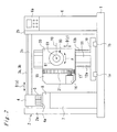
- This printer has a base 1 and a gate-like supporting frame 2.
- the gate-like supporting frame 2 is fixed on the base 1 and comprises a pair of left and right supporting legs 2a, 2b and a supporting beam 2c connecting the upper ends of the supporting legs 2a, 2b and extending in a lateral direction.
- the printer also has a first controller 6 with an operator control panel 6a which is adjacent to the right supporting leg 2b and a second controller 7 with a maintenance station 8 which is adjacent to the left supporting leg 2a.
- the first and second controllers 6, 7 comprise various controllers such as a movement controller for controlling the movement and rotation of the respective components as will be described later, a printing controller for controlling the ejection of ink from the printer head, and a power controller.
- a pair of front and rear lateral guide rails 3a, 3b extending in the lateral direction (direction of the axis Y) on the upper surface of the supporting beam 2c and a printer head carriage 4 is mounted on the lateral guide rails 3a, 3b such that the printer head carriage 4 is movable in the lateral direction (i.e. movable in the direction shown by arrow D(y)).
- a traveling mechanism such as a ball screw mechanism is provided. By controlling the driving of the traveling mechanism, the lateral movement of the printer head carriage 4 can be controlled. Since such traveling mechanism is well known in the art, the description of the structure will be omitted.
- the printer head carriage 4 is a member which extends forward from a portion supported by the lateral guide rails 3a, 3b, is bent downward, and extends forward again, that is the printer head carriage 4 has a crank shape as seen from a side.
- a front end portion 4a of the printer head carriage 4 is mounted on a front end portion 4a of the printer head carriage 4 .
- the printer head modules 5, also called inkjet head modules, are each provided with a number of ink nozzle holes formed in the bottom thereof and, for example, eject respective inks of different colors from the ink nozzle holes.
- the control of ink ejection is conducted by the printing controller for every ink nozzle hole. Since such control is conventionally well known in the art, the description of the structure will be omitted.
- the printer head module 5 itself or the printer head carriage 4 with the printer head modules 5 corresponds to "the printer head” defined in claims of the present invention.
- the printer head carriage 4 with the printer head modules 5 is movable along the lateral guide rails 3a, 3b in the lateral direction.
- the maintenance station 8 is moved upward to prevent the ink nozzle holes in the bottoms of the printer head modules 5 from being dried and to clean the ink nozzle holes.
- a pair of anteroposterior guide rails 1a, 1b extending in the anteroposterior direction (direction of the axis X) are arranged on the base 1 between the left and right supporting legs 2a, 2b of the gate-like supporting frame 2.
- a first supporting member 10 is mounted such that the first supporting member 10 is movable along the anteroposterior guide rails 1a, 1b in the anteroposterior direction (i.e. movable in the direction shown by the arrow D(x)).
- a traveling mechanism such as a ball screw mechanism is provided. By controlling the driving of the traveling mechanism, the anteroposterior movement of the first supporting member 10 can be controlled. Since such traveling mechanism is well known in the art, the description of the structure will be omitted.
- a vertical supporting member 11 is fixed in a vertically standing state on the first supporting member 10. Attached to the front surface of the vertical supporting member 11 are a pair of vertical guide rails 12a, 12b extending in the vertical direction (the direction of the axis Z).
- a second supporting member 15 is mounted to and supported by the vertical guide rails 12a, 12b such that the second supporting member 15 is movable in the vertical direction (i.e. movable in the direction shown by the arrow D(z)).
- a traveling mechanism such as a ball screw mechanism is provided to allow the movement of the second supporting member 15 in the vertical direction. By controlling the driving of the traveling mechanism, the vertical movement of the second supporting member 15 can be controlled. Since such traveling mechanism is well known in the art, the description of the structure will be omitted.
- the front surface 15a of the second supporting member 15 is formed into a semicircular shape of which center is a first rotation axis Y0 extending in the direction of the axis Y passing through a prescribed point O1 (a point set to a position where the print substrate 80 will be positioned as will be described later) defined relative to the second supporting member 15.
- a third supporting member 20 has a rear surface 20a having a semicircular shape corresponding to the semicircular shape of the front surface 15a.
- the third supporting member 20 is disposed slidably along the front surface 15a.
- the rear surface 20a of the third supporting member 20 is movable and slidable relative to the front surface 15a of the second supporting member 15, thereby allowing the third supporting member 20 to rotate about the first rotation axis Y0 relative to the second supporting member 15 (i.e. rotate in the direction shown by the arrow B).
- the third supporting member 20 is supported by the second supporting member 15 in the aforementioned manner.
- the third supporting member 20 is provided with internal teeth 21 which are formed in a front surface of a left-side portion, in Fig. 2, thereof and of which center is the first rotation axis Y0.
- a driving motor 16 is mounted on a front surface of a left-side portion of the second supporting member 15 and is provided with a driving pinion 17 attached to a driving shaft thereof.
- the driving pinion 17 is meshed with the internal teeth 21.
- the driving pinion 17 is driven to rotate by the driving motor 16
- the internal teeth 21 meshed with the driving pinion 17 are driven to rotate, thereby rotating the third supporting member 20 about the first rotation axis Y0.
- a holding shaft 25 extends in the anteroposterior direction (the direction of the axis X) and projects forward from the front surface of the third supporting member 20 in such a manner that the holding shaft 25 is rotatable about a second rotation axis X0 passing through the aforementioned prescribed point O1.
- a holding chuck 26 for holding the print substrate is attached to the front end of the holding shaft 25.
- the holding shaft 25 is driven to rotate by a driving motor (not shown) which is disposed within the third supporting member 20 and the holding chuck 26 has a structure capable of holding the print substrate 80. As the holding shaft 25 is driven to rotate with the print substrate 80 held by the holding chuck 26, the print substrate 80 is rotated about the second rotation axis X0.
- the holding shaft 25 and the holding chuck 26 compose the holding device defined by claims.
- the second rotation axis X0 extends in the anteroposterior direction (the direction of the axis X) when the third supporting member 20 is positioned at a predetermined rotational position (the rotational position shown in Fig. 3). Since the third supporting member 20 is rotatable about the first rotation axis Y0 as mentioned above, the second rotational axis X0 is inclined upward or downward according to the rotational position of the third supporting member 20. Though the first rotation axis Y0 and the second rotation axis X0 both pass the prescribed point O1 and cross each other in the illustrated example, these may not cross each other, that is, may be shifted from each other. However, the first rotation axis Y0 and the second rotation axis X0 preferably cross each other because the position calculation of the print substrate 80 is facilitated and the control by the movement controller is facilitated.
- the second rotation axis X0 as the rotation center of the holding shaft 25 corresponds to the axis X in the arrangement for explaining the operation principle shown in Fig. 1
- the first rotation axis Y0 as the rotation center of the third supporting member 20 corresponds to the axis Y in the arrangement for explaining the operation principle shown in Fig. 1.
- the second supporting member 15 supporting the third supporting member 20 is supported by the first supporting member 10 in such a manner as to allow the second supporting member 15 to move in the direction of the axis Z (the vertical direction) (i.e.
- the printer head is supported above the print substrate 80 in such a manner as to allow the printer head to move in the direction of the axis Y (the lateral direction) relative to the base 1 (i.e. to move in the direction shown by the allow D(y)). That is, the printer is adapted to perform the same actions as explained in the operation principle as shown in Fig. 1.
- the printer as shown in Fig. 2 through Fig. 4 can perform the desired printing by ejecting ink from the ink nozzle holes formed in the bottom of the printer head modules 5 onto the surface 81 of the print substrate 80 according to the operation principle explained with reference to Fig. 1.
- the configuration of the print substrate is not limited thereto and the printing can be performed on any curved surface including a cylindrical surface and a spherical surface.
Landscapes
- Engineering & Computer Science (AREA)
- Manufacturing & Machinery (AREA)
- Chemical & Material Sciences (AREA)
- Materials Engineering (AREA)
- Ink Jet (AREA)
Applications Claiming Priority (1)
| Application Number | Priority Date | Filing Date | Title |
|---|---|---|---|
| JP2006300520A JP2008114493A (ja) | 2006-11-06 | 2006-11-06 | 三次元プリンタ |
Publications (3)
| Publication Number | Publication Date |
|---|---|
| EP1918113A2 true EP1918113A2 (de) | 2008-05-07 |
| EP1918113A3 EP1918113A3 (de) | 2008-07-30 |
| EP1918113B1 EP1918113B1 (de) | 2015-10-14 |
Family
ID=39105889
Family Applications (1)
| Application Number | Title | Priority Date | Filing Date |
|---|---|---|---|
| EP07290781.9A Not-in-force EP1918113B1 (de) | 2006-11-06 | 2007-06-25 | Dreidimensionaler Drucker |
Country Status (5)
| Country | Link |
|---|---|
| US (1) | US7819055B2 (de) |
| EP (1) | EP1918113B1 (de) |
| JP (1) | JP2008114493A (de) |
| KR (1) | KR20080041095A (de) |
| CN (1) | CN101177073A (de) |
Cited By (4)
| Publication number | Priority date | Publication date | Assignee | Title |
|---|---|---|---|---|
| GB2448963A (en) * | 2007-05-01 | 2008-11-05 | Darren Lee Haward | Inkjet printing on cylindrical or spherical components |
| EP2283932A4 (de) * | 2008-12-11 | 2014-02-12 | Mimaki Eng Kk | Dreidimensionaler tintenstrahldrucker |
| CN104553342A (zh) * | 2013-10-11 | 2015-04-29 | 中国印刷科学技术研究所 | 彩色三维曲面喷墨印刷设备 |
| EP1972456B1 (de) * | 2007-03-09 | 2019-08-28 | Mimaki Engineering Co., Ltd. | Drucker für dreidimensionale Objekte |
Families Citing this family (49)
| Publication number | Priority date | Publication date | Assignee | Title |
|---|---|---|---|---|
| JP2010128936A (ja) * | 2008-11-28 | 2010-06-10 | Mimaki Engineering Co Ltd | 印刷回数指定装置、印刷回数指定方法、印刷回数指定プログラム、印刷回数識別装置、印刷回数識別方法、及び、印刷回数識別プログラム。 |
| US9156204B2 (en) * | 2010-05-17 | 2015-10-13 | Synerdyne Corporation | Hybrid scanner fabricator |
| US11701683B2 (en) | 2010-12-22 | 2023-07-18 | The Procter & Gamble Company | Methods for foil stamping parts having asymmetrical edges |
| US20130153156A1 (en) | 2011-12-20 | 2013-06-20 | Norm Henry Tiilikka | Foil Stamping Apparatus |
| CN102173211B (zh) * | 2010-12-28 | 2013-04-10 | 石毅 | 五轴联动控制立体打印设备及其控制方法 |
| US8683921B2 (en) | 2011-08-23 | 2014-04-01 | The Beckwood Corporation, Inc. | Modular decorating machine for conical products |
| USD688741S1 (en) * | 2012-08-23 | 2013-08-27 | B9Creations, LLC | Three-dimensional printer |
| JP2014065023A (ja) * | 2012-09-04 | 2014-04-17 | Mimaki Engineering Co Ltd | 保持治具、印刷装置及び印刷方法 |
| DK2892708T3 (en) | 2012-09-05 | 2019-01-28 | Aprecia Pharmaceuticals LLC | THREE-DIMENSIONAL PRESSURE SYSTEM AND EQUIPMENT |
| US8888480B2 (en) | 2012-09-05 | 2014-11-18 | Aprecia Pharmaceuticals Company | Three-dimensional printing system and equipment assembly |
| EP2730418B1 (de) * | 2012-11-12 | 2015-06-03 | Lite-on Mobile Oyj | 3D-Ausgabevorrichtung und -verfahren |
| DK2919994T3 (en) | 2012-11-15 | 2017-07-24 | Velox-Puredigital Ltd | PRINTING SYSTEM AND PROCEDURE |
| DE102012224237B4 (de) * | 2012-12-21 | 2024-08-08 | Krones Aktiengesellschaft | Vorrichtung und Verfahren für das Bedrucken von Behältern |
| CA152094S (en) * | 2013-02-18 | 2014-05-01 | Dws Srl | Stereolithography machine |
| DE102013101693B9 (de) | 2013-02-20 | 2015-11-12 | Notion Systems GmbH | Oberflächenbearbeitungsvorrichtung |
| USD722108S1 (en) * | 2013-03-13 | 2015-02-03 | Formlabs, Inc. | Three-dimensional printer |
| CA2906029C (en) | 2013-03-15 | 2017-09-05 | Aprecia Pharmaceuticals Company | Rapid disperse dosage form containing levetiracetam |
| USD754763S1 (en) * | 2013-03-15 | 2016-04-26 | Arburg Gmbh + Co. Kg | Device for producing three-dimensional articles |
| USD729309S1 (en) * | 2013-04-12 | 2015-05-12 | Pirate3Dp Pte. Ltd. | Three-dimensional printer |
| CN103341626B (zh) * | 2013-06-08 | 2015-09-23 | 王奉瑾 | 一种铸造式3d打印机 |
| CN104553422B (zh) * | 2013-10-11 | 2017-05-17 | 中国印刷科学技术研究所 | 彩色三维曲面喷墨印刷方法 |
| USD736838S1 (en) * | 2013-12-20 | 2015-08-18 | Maurizio Ettore Costabeber | Stereolithography machine |
| US9527272B2 (en) | 2014-03-07 | 2016-12-27 | Polar 3D Llc | Method for printing a three-dimensional object |
| TWD172647S (zh) * | 2014-05-30 | 2015-12-21 | 金寶電子工業股份有限公司 | 3d印表機之部分 |
| USD770545S1 (en) * | 2014-06-02 | 2016-11-01 | Natural Machines, Inc. | Three-dimensional printer |
| KR20160010202A (ko) | 2014-07-18 | 2016-01-27 | 정해영 | 보강재 투입수단이 구비된 3d 프린터 |
| USD738410S1 (en) * | 2014-09-24 | 2015-09-08 | Xyzprinting, Inc. | Chassis of 3D printer |
| CN104339657A (zh) * | 2014-10-09 | 2015-02-11 | 合肥海闻自动化设备有限公司 | 一种三维彩色喷墨增材打印机的自由度平台 |
| JP1523962S (de) | 2014-10-21 | 2015-05-18 | ||
| JP1523475S (de) * | 2014-10-21 | 2015-05-18 | ||
| USD732586S1 (en) * | 2014-11-13 | 2015-06-23 | Xyzprinting, Inc. | 3D printer |
| USD732587S1 (en) * | 2014-11-13 | 2015-06-23 | Xyzprinting, Inc. | 3D printer |
| USD757132S1 (en) * | 2015-01-04 | 2016-05-24 | Xyzprinting, Inc. | 3D printer |
| USD732588S1 (en) * | 2015-01-05 | 2015-06-23 | Xyzprinting, Inc. | 3D printer |
| ITRM20150111A1 (it) * | 2015-03-16 | 2016-09-16 | Lorusso Alessio | Sistema di movimentazione meccatronica per una macchina per la prototipazione rapida |
| CN104742372B (zh) * | 2015-04-02 | 2016-08-24 | 宁夏共享模具有限公司 | 基于fdm的3d打印设备 |
| CN104760293B (zh) * | 2015-04-28 | 2017-09-22 | 清华大学 | 空间大型桁架结构在轨制造的装置 |
| USD763332S1 (en) * | 2015-05-31 | 2016-08-09 | Huai Wu | 3D printhead |
| DE102016209649A1 (de) | 2015-07-08 | 2017-01-12 | Heidelberger Druckmaschinen Aktiengesellschaft | Vorrichtung zum Bedrucken von mehrdimensionalen Objekten |
| CN105015181A (zh) * | 2015-08-05 | 2015-11-04 | 意科赛特数码科技(江苏)有限公司 | 在带手柄的马克杯上直接喷图案的打印装置 |
| JP6903659B2 (ja) | 2015-08-21 | 2021-07-14 | アプレシア・ファーマスーティカルズ・エルエルシー | 3次元プリントシステムおよび装置アセンブリ |
| US10807273B2 (en) * | 2015-11-23 | 2020-10-20 | Lawrence Livermore National Security, Llc | High temperature additive manufacturing print head |
| CN108495752B (zh) * | 2016-01-15 | 2020-07-24 | 北京美科艺数码科技发展有限公司 | 一种喷墨打印装置及打印方法 |
| CN105711095B (zh) * | 2016-03-18 | 2017-09-29 | 浙江大学 | 三维打印用的支撑装置以及三维打印方法 |
| CN106004046B (zh) * | 2016-06-12 | 2019-05-10 | 东莞市基汇实业有限公司 | 一种数码平板打印机 |
| US10765658B2 (en) | 2016-06-22 | 2020-09-08 | Mastix LLC | Oral compositions delivering therapeutically effective amounts of cannabinoids |
| CN106827812B (zh) * | 2017-03-31 | 2019-06-25 | 西安德高印染自动化工程有限公司 | 一种三坐标跑台式数码喷墨印刷机 |
| CN116118353B (zh) * | 2022-12-15 | 2024-05-03 | 贵州电网有限责任公司 | 一种基于电流体喷印的立体金属线圈制备装置 |
| US12344010B2 (en) * | 2022-12-22 | 2025-07-01 | The Boeing Company | Multi-printhead end effector and associated system and method |
Family Cites Families (13)
| Publication number | Priority date | Publication date | Assignee | Title |
|---|---|---|---|---|
| US4254706A (en) * | 1979-03-22 | 1981-03-10 | American Screen Printing Equipment Company | Accessory for printing oval objects |
| US5144330A (en) * | 1990-12-21 | 1992-09-01 | Bennett Charles G | Method and apparatus for printing on pipe |
| JPH11223705A (ja) | 1998-02-05 | 1999-08-17 | Hoya Corp | 光学レンズ着色システム |
| JP2000006493A (ja) | 1998-06-29 | 2000-01-11 | Ikegami Tsushinki Co Ltd | 立体プリント装置 |
| US6050182A (en) * | 1999-02-18 | 2000-04-18 | Arsenault; Germain | Inflatable balloon color printing process and apparatus |
| JP2001191514A (ja) | 1999-10-25 | 2001-07-17 | Seiko Epson Corp | 記録方法及び記録装置 |
| US6460958B2 (en) * | 2000-02-29 | 2002-10-08 | Minolta Co., Ltd. | Three-dimensional object printing apparatus and method |
| JP2003191455A (ja) | 2001-12-25 | 2003-07-08 | Hitachi Printing Solutions Ltd | インクジェット記録装置 |
| US6811648B1 (en) * | 2002-01-11 | 2004-11-02 | Polytype America Corporation | Method and machine for substantially simultaneously printing containers and applying labels thereto |
| US6817287B2 (en) * | 2002-05-31 | 2004-11-16 | Shadrach, Iii William S. | System for applying printed information to a package |
| JP2004148666A (ja) | 2002-10-30 | 2004-05-27 | Seiko Epson Corp | インクジェットプリンタ |
| FR2856337B1 (fr) * | 2003-06-23 | 2005-09-16 | Dubuit Mach | Machine d'impression d'objets |
| JP2008221496A (ja) * | 2007-03-09 | 2008-09-25 | Mimaki Engineering Co Ltd | 三次元プリンタ |
-
2006
- 2006-11-06 JP JP2006300520A patent/JP2008114493A/ja active Pending
-
2007
- 2007-04-23 US US11/738,803 patent/US7819055B2/en active Active
- 2007-05-21 KR KR1020070049173A patent/KR20080041095A/ko not_active Withdrawn
- 2007-06-11 CN CNA2007101107542A patent/CN101177073A/zh active Pending
- 2007-06-25 EP EP07290781.9A patent/EP1918113B1/de not_active Not-in-force
Non-Patent Citations (1)
| Title |
|---|
| None |
Cited By (4)
| Publication number | Priority date | Publication date | Assignee | Title |
|---|---|---|---|---|
| EP1972456B1 (de) * | 2007-03-09 | 2019-08-28 | Mimaki Engineering Co., Ltd. | Drucker für dreidimensionale Objekte |
| GB2448963A (en) * | 2007-05-01 | 2008-11-05 | Darren Lee Haward | Inkjet printing on cylindrical or spherical components |
| EP2283932A4 (de) * | 2008-12-11 | 2014-02-12 | Mimaki Eng Kk | Dreidimensionaler tintenstrahldrucker |
| CN104553342A (zh) * | 2013-10-11 | 2015-04-29 | 中国印刷科学技术研究所 | 彩色三维曲面喷墨印刷设备 |
Also Published As
| Publication number | Publication date |
|---|---|
| JP2008114493A (ja) | 2008-05-22 |
| EP1918113A3 (de) | 2008-07-30 |
| KR20080041095A (ko) | 2008-05-09 |
| US20080105144A1 (en) | 2008-05-08 |
| EP1918113B1 (de) | 2015-10-14 |
| CN101177073A (zh) | 2008-05-14 |
| US7819055B2 (en) | 2010-10-26 |
Similar Documents
| Publication | Publication Date | Title |
|---|---|---|
| EP1918113B1 (de) | Dreidimensionaler Drucker | |
| EP1972456B1 (de) | Drucker für dreidimensionale Objekte | |
| EP1967373A1 (de) | Drucker für dreidimensionale Objekte | |
| EP1967372A1 (de) | Drucker für dreidimensionale Objekte | |
| US9346298B2 (en) | Single-pass inkjet printer | |
| JP6518329B2 (ja) | プリントヘッドモジュール | |
| JP6633088B2 (ja) | シングルパスインクジェットプリンタ | |
| JPWO2010067445A6 (ja) | 三次元インクジェットプリンタ | |
| JP2009184118A (ja) | 三次元プリンタ | |
| JP2009184119A (ja) | 3次元プリンタ | |
| JP5322605B2 (ja) | インクジェットプリンタ | |
| JP2009184121A (ja) | 3次元プリンタ | |
| JP5016509B2 (ja) | 三次元プリンタ | |
| JP2006335018A (ja) | 円錐メディアプリント用のインクジェットプリンタとそれを用いたプリント方法 | |
| JP2010125744A (ja) | インクジェットプリンタ | |
| KR100993344B1 (ko) | 잉크젯헤드 고정장치 | |
| JP3659465B2 (ja) | インクジェットプリンタ | |
| JP2018183995A (ja) | 印刷ヘッド用の組付装置 | |
| JP2006290544A (ja) | 搬送機構の支持構造及び画像記録装置 |
Legal Events
| Date | Code | Title | Description |
|---|---|---|---|
| PUAI | Public reference made under article 153(3) epc to a published international application that has entered the european phase |
Free format text: ORIGINAL CODE: 0009012 |
|
| AK | Designated contracting states |
Kind code of ref document: A2 Designated state(s): AT BE BG CH CY CZ DE DK EE ES FI FR GB GR HU IE IS IT LI LT LU LV MC MT NL PL PT RO SE SI SK TR |
|
| AX | Request for extension of the european patent |
Extension state: AL BA HR MK RS |
|
| PUAL | Search report despatched |
Free format text: ORIGINAL CODE: 0009013 |
|
| AK | Designated contracting states |
Kind code of ref document: A3 Designated state(s): AT BE BG CH CY CZ DE DK EE ES FI FR GB GR HU IE IS IT LI LT LU LV MC MT NL PL PT RO SE SI SK TR |
|
| AX | Request for extension of the european patent |
Extension state: AL BA HR MK RS |
|
| 17P | Request for examination filed |
Effective date: 20080902 |
|
| 17Q | First examination report despatched |
Effective date: 20081031 |
|
| AKX | Designation fees paid |
Designated state(s): AT BE BG CH CY CZ DE DK EE ES FI FR GB GR HU IE IS IT LI LT LU LV MC MT NL PL PT RO SE SI SK TR |
|
| GRAP | Despatch of communication of intention to grant a patent |
Free format text: ORIGINAL CODE: EPIDOSNIGR1 |
|
| INTG | Intention to grant announced |
Effective date: 20150527 |
|
| GRAS | Grant fee paid |
Free format text: ORIGINAL CODE: EPIDOSNIGR3 |
|
| GRAA | (expected) grant |
Free format text: ORIGINAL CODE: 0009210 |
|
| AK | Designated contracting states |
Kind code of ref document: B1 Designated state(s): AT BE BG CH CY CZ DE DK EE ES FI FR GB GR HU IE IS IT LI LT LU LV MC MT NL PL PT RO SE SI SK TR |
|
| REG | Reference to a national code |
Ref country code: GB Ref legal event code: FG4D |
|
| REG | Reference to a national code |
Ref country code: AT Ref legal event code: REF Ref document number: 754810 Country of ref document: AT Kind code of ref document: T Effective date: 20151015 Ref country code: CH Ref legal event code: EP |
|
| REG | Reference to a national code |
Ref country code: IE Ref legal event code: FG4D |
|
| REG | Reference to a national code |
Ref country code: DE Ref legal event code: R096 Ref document number: 602007043478 Country of ref document: DE |
|
| REG | Reference to a national code |
Ref country code: NL Ref legal event code: MP Effective date: 20151014 |
|
| REG | Reference to a national code |
Ref country code: LT Ref legal event code: MG4D |
|
| REG | Reference to a national code |
Ref country code: AT Ref legal event code: MK05 Ref document number: 754810 Country of ref document: AT Kind code of ref document: T Effective date: 20151014 |
|
| PG25 | Lapsed in a contracting state [announced via postgrant information from national office to epo] |
Ref country code: NL Free format text: LAPSE BECAUSE OF FAILURE TO SUBMIT A TRANSLATION OF THE DESCRIPTION OR TO PAY THE FEE WITHIN THE PRESCRIBED TIME-LIMIT Effective date: 20151014 Ref country code: IS Free format text: LAPSE BECAUSE OF FAILURE TO SUBMIT A TRANSLATION OF THE DESCRIPTION OR TO PAY THE FEE WITHIN THE PRESCRIBED TIME-LIMIT Effective date: 20160214 Ref country code: IT Free format text: LAPSE BECAUSE OF FAILURE TO SUBMIT A TRANSLATION OF THE DESCRIPTION OR TO PAY THE FEE WITHIN THE PRESCRIBED TIME-LIMIT Effective date: 20151014 Ref country code: LT Free format text: LAPSE BECAUSE OF FAILURE TO SUBMIT A TRANSLATION OF THE DESCRIPTION OR TO PAY THE FEE WITHIN THE PRESCRIBED TIME-LIMIT Effective date: 20151014 Ref country code: ES Free format text: LAPSE BECAUSE OF FAILURE TO SUBMIT A TRANSLATION OF THE DESCRIPTION OR TO PAY THE FEE WITHIN THE PRESCRIBED TIME-LIMIT Effective date: 20151014 |
|
| REG | Reference to a national code |
Ref country code: FR Ref legal event code: PLFP Year of fee payment: 10 |
|
| PG25 | Lapsed in a contracting state [announced via postgrant information from national office to epo] |
Ref country code: PT Free format text: LAPSE BECAUSE OF FAILURE TO SUBMIT A TRANSLATION OF THE DESCRIPTION OR TO PAY THE FEE WITHIN THE PRESCRIBED TIME-LIMIT Effective date: 20160215 Ref country code: AT Free format text: LAPSE BECAUSE OF FAILURE TO SUBMIT A TRANSLATION OF THE DESCRIPTION OR TO PAY THE FEE WITHIN THE PRESCRIBED TIME-LIMIT Effective date: 20151014 Ref country code: SE Free format text: LAPSE BECAUSE OF FAILURE TO SUBMIT A TRANSLATION OF THE DESCRIPTION OR TO PAY THE FEE WITHIN THE PRESCRIBED TIME-LIMIT Effective date: 20151014 Ref country code: FI Free format text: LAPSE BECAUSE OF FAILURE TO SUBMIT A TRANSLATION OF THE DESCRIPTION OR TO PAY THE FEE WITHIN THE PRESCRIBED TIME-LIMIT Effective date: 20151014 Ref country code: LV Free format text: LAPSE BECAUSE OF FAILURE TO SUBMIT A TRANSLATION OF THE DESCRIPTION OR TO PAY THE FEE WITHIN THE PRESCRIBED TIME-LIMIT Effective date: 20151014 Ref country code: GR Free format text: LAPSE BECAUSE OF FAILURE TO SUBMIT A TRANSLATION OF THE DESCRIPTION OR TO PAY THE FEE WITHIN THE PRESCRIBED TIME-LIMIT Effective date: 20160115 Ref country code: PL Free format text: LAPSE BECAUSE OF FAILURE TO SUBMIT A TRANSLATION OF THE DESCRIPTION OR TO PAY THE FEE WITHIN THE PRESCRIBED TIME-LIMIT Effective date: 20151014 |
|
| REG | Reference to a national code |
Ref country code: DE Ref legal event code: R097 Ref document number: 602007043478 Country of ref document: DE |
|
| PG25 | Lapsed in a contracting state [announced via postgrant information from national office to epo] |
Ref country code: CZ Free format text: LAPSE BECAUSE OF FAILURE TO SUBMIT A TRANSLATION OF THE DESCRIPTION OR TO PAY THE FEE WITHIN THE PRESCRIBED TIME-LIMIT Effective date: 20151014 |
|
| PLBE | No opposition filed within time limit |
Free format text: ORIGINAL CODE: 0009261 |
|
| STAA | Information on the status of an ep patent application or granted ep patent |
Free format text: STATUS: NO OPPOSITION FILED WITHIN TIME LIMIT |
|
| PG25 | Lapsed in a contracting state [announced via postgrant information from national office to epo] |
Ref country code: RO Free format text: LAPSE BECAUSE OF FAILURE TO SUBMIT A TRANSLATION OF THE DESCRIPTION OR TO PAY THE FEE WITHIN THE PRESCRIBED TIME-LIMIT Effective date: 20151014 Ref country code: DK Free format text: LAPSE BECAUSE OF FAILURE TO SUBMIT A TRANSLATION OF THE DESCRIPTION OR TO PAY THE FEE WITHIN THE PRESCRIBED TIME-LIMIT Effective date: 20151014 Ref country code: EE Free format text: LAPSE BECAUSE OF FAILURE TO SUBMIT A TRANSLATION OF THE DESCRIPTION OR TO PAY THE FEE WITHIN THE PRESCRIBED TIME-LIMIT Effective date: 20151014 Ref country code: SK Free format text: LAPSE BECAUSE OF FAILURE TO SUBMIT A TRANSLATION OF THE DESCRIPTION OR TO PAY THE FEE WITHIN THE PRESCRIBED TIME-LIMIT Effective date: 20151014 |
|
| 26N | No opposition filed |
Effective date: 20160715 |
|
| PG25 | Lapsed in a contracting state [announced via postgrant information from national office to epo] |
Ref country code: SI Free format text: LAPSE BECAUSE OF FAILURE TO SUBMIT A TRANSLATION OF THE DESCRIPTION OR TO PAY THE FEE WITHIN THE PRESCRIBED TIME-LIMIT Effective date: 20151014 |
|
| PG25 | Lapsed in a contracting state [announced via postgrant information from national office to epo] |
Ref country code: BE Free format text: LAPSE BECAUSE OF FAILURE TO SUBMIT A TRANSLATION OF THE DESCRIPTION OR TO PAY THE FEE WITHIN THE PRESCRIBED TIME-LIMIT Effective date: 20151014 |
|
| PG25 | Lapsed in a contracting state [announced via postgrant information from national office to epo] |
Ref country code: MC Free format text: LAPSE BECAUSE OF FAILURE TO SUBMIT A TRANSLATION OF THE DESCRIPTION OR TO PAY THE FEE WITHIN THE PRESCRIBED TIME-LIMIT Effective date: 20151014 |
|
| REG | Reference to a national code |
Ref country code: CH Ref legal event code: PL |
|
| REG | Reference to a national code |
Ref country code: IE Ref legal event code: MM4A |
|
| PG25 | Lapsed in a contracting state [announced via postgrant information from national office to epo] |
Ref country code: CH Free format text: LAPSE BECAUSE OF NON-PAYMENT OF DUE FEES Effective date: 20160630 Ref country code: LI Free format text: LAPSE BECAUSE OF NON-PAYMENT OF DUE FEES Effective date: 20160630 |
|
| REG | Reference to a national code |
Ref country code: FR Ref legal event code: PLFP Year of fee payment: 11 |
|
| PG25 | Lapsed in a contracting state [announced via postgrant information from national office to epo] |
Ref country code: IE Free format text: LAPSE BECAUSE OF NON-PAYMENT OF DUE FEES Effective date: 20160625 |
|
| REG | Reference to a national code |
Ref country code: FR Ref legal event code: PLFP Year of fee payment: 12 |
|
| PG25 | Lapsed in a contracting state [announced via postgrant information from national office to epo] |
Ref country code: CY Free format text: LAPSE BECAUSE OF FAILURE TO SUBMIT A TRANSLATION OF THE DESCRIPTION OR TO PAY THE FEE WITHIN THE PRESCRIBED TIME-LIMIT Effective date: 20151014 Ref country code: HU Free format text: LAPSE BECAUSE OF FAILURE TO SUBMIT A TRANSLATION OF THE DESCRIPTION OR TO PAY THE FEE WITHIN THE PRESCRIBED TIME-LIMIT; INVALID AB INITIO Effective date: 20070625 |
|
| PG25 | Lapsed in a contracting state [announced via postgrant information from national office to epo] |
Ref country code: TR Free format text: LAPSE BECAUSE OF FAILURE TO SUBMIT A TRANSLATION OF THE DESCRIPTION OR TO PAY THE FEE WITHIN THE PRESCRIBED TIME-LIMIT Effective date: 20151014 Ref country code: MT Free format text: LAPSE BECAUSE OF NON-PAYMENT OF DUE FEES Effective date: 20160630 Ref country code: LU Free format text: LAPSE BECAUSE OF NON-PAYMENT OF DUE FEES Effective date: 20160625 |
|
| PG25 | Lapsed in a contracting state [announced via postgrant information from national office to epo] |
Ref country code: BG Free format text: LAPSE BECAUSE OF FAILURE TO SUBMIT A TRANSLATION OF THE DESCRIPTION OR TO PAY THE FEE WITHIN THE PRESCRIBED TIME-LIMIT Effective date: 20151014 |
|
| PGFP | Annual fee paid to national office [announced via postgrant information from national office to epo] |
Ref country code: GB Payment date: 20220506 Year of fee payment: 16 Ref country code: FR Payment date: 20220510 Year of fee payment: 16 Ref country code: DE Payment date: 20220505 Year of fee payment: 16 |
|
| P01 | Opt-out of the competence of the unified patent court (upc) registered |
Effective date: 20230522 |
|
| REG | Reference to a national code |
Ref country code: DE Ref legal event code: R119 Ref document number: 602007043478 Country of ref document: DE |
|
| GBPC | Gb: european patent ceased through non-payment of renewal fee |
Effective date: 20230625 |
|
| PG25 | Lapsed in a contracting state [announced via postgrant information from national office to epo] |
Ref country code: DE Free format text: LAPSE BECAUSE OF NON-PAYMENT OF DUE FEES Effective date: 20240103 Ref country code: GB Free format text: LAPSE BECAUSE OF NON-PAYMENT OF DUE FEES Effective date: 20230625 |
|
| PG25 | Lapsed in a contracting state [announced via postgrant information from national office to epo] |
Ref country code: FR Free format text: LAPSE BECAUSE OF NON-PAYMENT OF DUE FEES Effective date: 20230630 |