EP1917439B1 - Pompes péristaltiques axiales rotatives et procédés associés - Google Patents
Pompes péristaltiques axiales rotatives et procédés associés Download PDFInfo
- Publication number
- EP1917439B1 EP1917439B1 EP06790047.2A EP06790047A EP1917439B1 EP 1917439 B1 EP1917439 B1 EP 1917439B1 EP 06790047 A EP06790047 A EP 06790047A EP 1917439 B1 EP1917439 B1 EP 1917439B1
- Authority
- EP
- European Patent Office
- Prior art keywords
- tube
- cam
- fingers
- finger
- cassette
- Prior art date
- Legal status (The legal status is an assumption and is not a legal conclusion. Google has not performed a legal analysis and makes no representation as to the accuracy of the status listed.)
- Not-in-force
Links
Images


Classifications
-
- F—MECHANICAL ENGINEERING; LIGHTING; HEATING; WEAPONS; BLASTING
- F04—POSITIVE - DISPLACEMENT MACHINES FOR LIQUIDS; PUMPS FOR LIQUIDS OR ELASTIC FLUIDS
- F04B—POSITIVE-DISPLACEMENT MACHINES FOR LIQUIDS; PUMPS
- F04B43/00—Machines, pumps, or pumping installations having flexible working members
- F04B43/08—Machines, pumps, or pumping installations having flexible working members having tubular flexible members
- F04B43/082—Machines, pumps, or pumping installations having flexible working members having tubular flexible members the tubular flexible member being pressed against a wall by a number of elements, each having an alternating movement in a direction perpendicular to the axes of the tubular member and each having its own driving mechanism
-
- F—MECHANICAL ENGINEERING; LIGHTING; HEATING; WEAPONS; BLASTING
- F04—POSITIVE - DISPLACEMENT MACHINES FOR LIQUIDS; PUMPS FOR LIQUIDS OR ELASTIC FLUIDS
- F04B—POSITIVE-DISPLACEMENT MACHINES FOR LIQUIDS; PUMPS
- F04B43/00—Machines, pumps, or pumping installations having flexible working members
- F04B43/12—Machines, pumps, or pumping installations having flexible working members having peristaltic action
Definitions
- This invention relates generally to pumps and related methods and more specifically to peristaltic pumps and methods for pumping fluids that are useful in a variety of medical and non-medical applications.
- Peristaltic pumps are devices that transfer fluid through one or more elongate, at least partially flexible, tube(s) by compressing each tube in a peristaltic manner. Fluid transport through the tube is effectuated by moving a region of compression along the length of the tube. Such movement of the region of compression is typically achieved by way of one or more rollers or reciprocating pushers that progressively move an area of compression along the length of the tubing to thereby pump fluid through the tubing in a peristaltic motion.
- Such pumps are often used in medical applications including intravenous or subcutaneous infusion, withdrawal of fluids as in wound drainage systems as well as various laboratory instruments and industrial applications, such as industrial applications where toxic or corrosive fluids are pumped.
- Typical linear peristaltic pumps include those described in United States Patent Nos. 2,877,714 (Sorg et al. ), 4,671,792 (Borsannyi ), 4,893,991 (Hemingway et al. ) and 4,728,265 (Canon ). In general, these pumps require a drive shaft that is parallel to a resilient tube and a plurality of cams along the drive shaft to move pushers toward and away from the tube.
- Rotary peristaltic pumps generally dispose a resilient tube along a circular path, with a number of rollers mounted around the circumference of a circular rotor-sequentially rolling along the tube to occlude the tube and force liquid through the tube.
- Typical of such pumps are those disclosed in United States Patent Nos. 4,886,431 (Soderquist et al. ) and 3,172,367 (King ). These pumps often have relatively low efficiency and impose high shear and tension stresses on the tube causing internal tube wall erosion or spallation.
- the tube may eventually be permanently deformed so that the tube becomes flattened into a more oval shape and carries less liquid.
- the prior art has also included another type of peristaltic pump wherein a tube is arranged along a circular path and a cylindrical cam that rotates eccentrically is used to sequentially move a plurality of blunt pushers or fingers to sequentially compress regions of the tube from one end of the path to another and of the path.
- a cylindrical cam that rotates eccentrically is used to sequentially move a plurality of blunt pushers or fingers to sequentially compress regions of the tube from one end of the path to another and of the path.
- Examples of such pumps are described in German Patent No. 2,152,352 (Goner ) and Italian Patent No. 582,797 (Tubospir ). In general, these "finger" type peristaltic pumps tend to be less complex than linear peristaltic pumps.
- the pressure exerted by the blunt fingers on the tubing can reduce the useable life of the tubing and can, in at least some cases, cause internal tube wall erosion or spallation resulting in possible loss of particulate matter from the tube wall into the fluid stream.
- tubes with different wall thicknesses may not be accommodated by these pumps, since with thinner than standard tubes the fingers will not properly occlude the tube and with thicker than standard tubes the tube will close prematurely and be subject to excessive compression, requiring higher cam drive power and causing excessive wear on the cam and tube.
- peristaltic pump One type of peristaltic pump that is especially effective is the curvilinear peristaltic pump described in United States Patent No. 5,791,881 (Moubayed et al. ).
- a resilient tube is disposed against a generally circular platen and a rotating cam member sequentially and radially moves a plurality of fingers such that the fingers compress the tube and force the fluid through the tube in a peristaltic fashion.
- the cam drives the pump fingers in a radial direction.
- the pump must be large enough (in the radial direction) to accommodate the outer radial length of the cam, the height of the pump fingers and the thickness of the concave curved platen.
- SU 1,366,693 and SU 853,157 disclose peristaltic pumps.
- CH 503,2020 discloses a liquid pumping device.
- the present invention provides a peristaltic pump device (sometimes referred to herein as "rotary axial peristaltic pumps”) according to claim 1 and a method for pumping fluid according to claim 37.
- the pumps can provide advantages and/or useful improvements or differences over the peristaltic pumps of the prior art.
- a peristaltic pump device which generally comprises a platen assembly including a platen surface, a cam having a rotational axis and a cam surface spaced apart from the platen surface.
- the device comprises a plurality of fingers having a first portion in cooperative engagement with the cam surface and a second portion adjacent the platen surface and structured to engage and compress a tubing disposed along the platen surface.
- the device may further include a housing containing the cam and fingers.
- the platen assembly, cam and fingers may be operatively configured such that, when the cam is rotated about its rotational axis, the second portions of the fingers will reciprocate in a direction that is substantially parallel to the rotational axis of the cam, such that when a fluid filled compressible tubing is disposed along the platen surface, the reciprocating motion of the second portions of the fingers will effect pumping of the fluid through the tubing.
- the platen may comprise a substantially planar surface that is configured to receive a portion of compressible tubing parallel thereto.
- the platen assembly may include one or more tube holding member(s) (e.g., clips, ribs, notches, magnets, grooves, recesses, etc.) that hold or retain the compressible tubing in a desired position or configuration between the platen surface and the second portions of the fingers.
- the tube holding member(s) may comprise a plurality of spaced apart rib members, extending from the platen surface and including features, for example, cut out regions, for receiving and securing a tubing in an appropriate position along the platen surface.
- the platen assembly may comprise a door that is hingedly or pivotally connected to the housing, wherein such door includes the platen surface on an interior surface thereof.
- the door may be structured to facilitate installation and removal of the tubing, and maintenance of the device by allowing easy access to the tubing carrier as well as the fingers and/or other components of the system.
- the fingers of the pump may reciprocate back and forth on longitudinal axes that are generally perpendicular to the cam surface and generally parallel to an axis of rotation about which the cam rotates.
- elevations or lobes on the cam may cause the fingers to move in a direction substantially parallel to the cam rotational axis.
- the cam surface may be described as including a path, or a cam race on which the first portions of the fingers ride as the cam moves.
- the fingers may be aligned along a path defined by the cam race.
- the cam race is preferably located on a peripheral region of the cam, such cam race having one or more race surface(s) upon which the fingers ride.
- An axial plane may be projectable through the race surface(s), such axial plane being substantially perpendicular to the axis of rotation about which the cam rotates.
- the cam race includes elevated regions or lobes which, when the cam is rotated about the rotational axis, cause the second portions of the fingers to move back and forth along their longitudinal axes, thereby sequentially compressing and decompressing the tubing to effect pumping of fluid through the tubing.
- the first ends of the fingers may include moving members, for example rollers mounted on or within first ends of the fingers.
- These moving members e.g., rollers
- these rollers may be substantially spherical.
- the cam surface may include a substantially concave race.
- Such concave race may be configured such that the radius of the race is larger than the radius of the rollers.
- the race may comprise a groove or depression such that each of the rollers will contact opposing locations on the opposite side walls of the groove or depression.
- the race may comprise a tapered groove and the rollers may be correspondingly tapered so as to ride on a tapered wall of the race.
- the race may comprise a raised area or rail and the rollers may be correspondingly configured so as to ride on such raised area or rail.
- the race may comprise a wavy or curved cam surface and the rollers may be maintained in positions that cause the rollers to ride on such wavy or curved surface.
- the pump incorporates a spring(s) for actively retracting the fingers after they have compressed the tubing as intended, without requiring the fingers to be linked to the cam in such a way as to cause the cam to actively pull the fingers away from the tubing.
- the fingers may interact with spring(s) that cause retraction of the second end of each finger in a direction away from the platen surface after that finger has caused the desired compression of the tubing.
- the fingers may interact with spring(s) or other biasing apparatus that substantially maintain the fingers in operative engagement with the cam surface.
- Such spring(s) or other biasing apparatus may be structured to allow for a more precise degree of control over the operation of the fingers, and more precise control over pumping overall, relative to prior art devices which rely on resiliency or springiness of the tubing to cause retraction of pump fingers and/or which require the fingers to be coupled to the cam such that the cam not only pushes each finger to compress the tubing but also pulls each finger to cause it to retract away from the tubing.
- tip members may be located on the ends of some or all of the pump fingers. Such tip members may be spring biased or otherwise biased to provide a controlled amount of compressive force on the tubing such that the lumen of the tubing will be fully occluded or "pinched off" when the finger reaches its point of maximum travel but the compressive force on the tubing will not be so strong as to cause unnecessary stress or wear on the tubing. In at least some embodiments, the tip members will be narrower than the width of the compression surface of the finger. Such tip members may be shaped to provide for a discrete occlusion zone that extends transversely across the tubing when the finger reaches its point of maximum travel.
- the pump device may optionally include a strain gauge transducer or other apparatus that provides an indication of the degree or amount of deflection, expansion or contraction of the tubing as fluid is being pumped through the tubing.
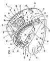
- Figures 1 and 2 show one embodiment of a rotary axial peristaltic pump device 10 of the present invention.
- the device 10 is shown in an "open” configuration for purposes of illustrating internal components of the device 10 more clearly.
- Figure 2 provides an end view of the same device 10 in a "closed” or operational configuration.
- the device 10 shown in Figures 1 and 2 generally comprises a housing 12 with a platen door 14 hingedly engaged thereto.
- the platen door 14 forms a part of a platen assembly 20 which includes a platen surface 22.
- the platen surface 22 comprises a substantially planar or substantially flat platen surface 22.
- This platen surface 22 may comprise, or may be positioned on, at least a peripheral region of the interior surface 23 of the platen door 14.
- This device 10 further comprises a cam 30 that rotates about an axis of rotation AR and has a cam surface 32 that is spaced apart from the platen surface 22 when the platen door 14 is in the closed position, such as that shown in Figure 2 .
- the cam 30 may rotate about the axis of rotation AR in a direction, such as that indicated by arrow 36. It is to be understood, however, that rotation of the cam 30 in the direction opposite arrow 36 is also possible.
- the device 10 shown in Figures 1 and 2 further comprises a plurality of fingers 44 which may form a finger assembly 45 mounted within the housing 12.
- the fingers 44 are aligned in a substantially arcuate array, one next to another, and substantially parallel (e.g., within approximate 10 degrees of parallel) to one another.
- the fingers 44 are aligned such that a longitudinal axis LA of each finger 44 is substantially parallel to the axis of rotation AR of the cam 30.
- each finger 44 may include a first portion 46 and a second portion 48.
- the first portion 46 is in cooperative engagement with the cam surface 32 and the second portion 48 is adjacent the platen surface 22.
- a tubing element 50 such as a flexible tube formed of suitable material (e.g., polyvinyl chloride (PVC), silicon, latex, polyurethane, etc.) is disposed between the second portions 48 of the fingers 44 and the platen surface 22.
- suitable material e.g., polyvinyl chloride (PVC), silicon, latex, polyurethane, etc.
- the cam 30 is rotatable about the axis of rotation AR by suitable means such as a motor driven gear mechanism 56 (shown in Figures 6A and 6B ).
- the device 10 is structured such that when the device 10 is in the closed or operational configuration and the cam 30 is rotated about the axis of rotation AR, the second portions 48 of the fingers 44 will reciprocate back an forth in the direction of their longitudinal axes LA, in other words, each finger 44 reciprocates back and forth on a longitudinal axis LA that is substantially parallel (e.g., within approximately 10 degrees of parallel) to the axis of rotation AR of the cam 30.
- the cam surface 32 may include regions having contours defining varying elevation of cam surface 32, such as lobes L.
- the contours of cam surface 32 effects a wave like, or peristaltic motion of the fingers 44 as the cam surface 32 travels beneath the first ends of the fingers 44. It will be appreciated that, in at least some embodiments, the greater the rate of change of the slope of the cam lobes L the more power required to operate the pump. Because the pump of the present invention may employ pump fingers whose longitudinal axis is substantially parallel to the axis of cam rotation, the circumference of the cam can extend nearly to the extent of the pump housing.
- a cam race that is located near the circumference of the cam thereby achieves a maximum cam race length without increasing the size of the envelope of the mechanism.
- the cam race length is substantially long compared to rise and fall of the cam lobes a small rate of change of the slope of the cam lobes is achieved thereby enabling pumps of the present invention to proved the same or greater pumping efficiency with less power consumption. In embodiments that are battery powered, this improved pumping efficiency may result in longer battery life.
- the pumps of this invention may utilize cams that rotate about an axis of rotation AR that is substantially parallel to the longitudinal axes LA of the fingers 44, such pumps of the present invention may be smaller in size than prior art peristaltic pumps of similar pumping capacity.
- the tubing element 50 may optionally be disposed on or in a tube cassette 60 and such cassette 60 may be located within the housing 12.
- the tube cassette 60 may be any suitable type of structure(s) or apparatus (e.g., frame, lattice, scaffold, series of clips, series of ribs, etc.) that when installed within the housing 12 will hold the tubing element 50 in a substantially fixed position or shape.
- Cassette 60 may comprise a frame 61 having a plurality of transverse members such as ribs 63 with notches 65 formed therein such that the tubing element 50 is received and held within the notches 65.
- ribs 63 may be sized and positioned to fit between the second portions 48 of adjacent fingers 44. This is shown, for example, in Figure 2 . In some embodiments the ribs 63 may be sized and positioned to facilitate alignment of the cassette tubing carrier 60 when the tubing carrier 60 is installed to the front housing surface 62.
- the tubing may be pre-mounted on or in the cassette 60, thereby eliminating the need for manual handling and mounting of the tubing element 50 within the pump device 10.
- the shape of the notches 65, or other cut away regions through which the tubing element 50 passes may be of generally triangular shape or may be otherwise shaped so as to assist or facilitate rebounding of the tubing element 50 to its fully, or near fully, expanded, non-compressed shape after it has been compressed by each finger 44.
- Such notches 65 or other suitable tube-constraining or tube-contacting structures provide partial compression or resistance to expansion of the tubing element 50 in a direction that is generally perpendicular to the direction in which the finger 44 compresses the tubing element 50, thereby countering the compressive effect on the tubing element 50 and facilitating rapid re-expansion of the tubing element 50 as the finger 44 is withdrawn away from the tubing element 50.
- the cassette 60 may include a tag, barcode, sensor, switch, triggering mechanism, identifying protrusion(s), machine readable element(s) or other apparatus/material that will enable a sensing (e.g., detecting) component of the pump device 10 (e.g., a sensor that is in communication with a computer, controller or other processor) to identify a particular cassette 60, or a particular size/type of cassette 60, or to identify the presence or absence of the cassette 60 and, optionally, to disable the pump device 10 or provide an alarm (e.g., audible alarm, light, etc) or other signal when the cassette 60 is absent, improperly positioned or of an incorrect size/type, etc.
- a sensing component of the pump device 10 e.g., a sensor that is in communication with a computer, controller or other processor
- an alarm e.g., audible alarm, light, etc
- the housing 12 may include a back support plate 67 held together by plurality of bolts for ease of assembly and disassembly as needed.
- the housing 12 supports the hinged platen door 14 which pivots about hinge pins 66 coupling the door 14 to the housing 12. When in the closed position, the door 14 rests against a cover stop 68, and a latch 72 hooks over the door 14 securing the door 14 in the closed position.
- the door 14 In the closed position, such as shown in Figure 2 , the door 14 provides a substantially flat or substantially planar platen surface for compression of the resilient tubing 50 held in the cassette tubing carrier 60.
- the door 14 may be opened and released by lifting the latch 72.
- the door 14 When not latched in the closed position, the door 14 is free to swing to a fully open position as illustrated in Figure 1 . It is to be appreciated that other arrangements are also possible for effectively and conveniently securing the platen assembly to the cam and plurality of fingers in a functional manner, and such arrangements are considered to be within the scope of the present invention.
- the housing 12 substantially encapsulates or contains the plurality of fingers 44.
- Each of the fingers 44 is oriented in an axial direction with respect to the rotation of the cam 30.
- the fingers 44 are positioned within individual housing cavities, for example defined by interior walls of the housing 12 located near the circumference thereof.
- the individual housing cavities may comprise a plurality of hollow cavities or chambers having finger-guiding surfaces 86 oriented axially with respect to the cam rotational axis.
- a single housing cavity may be provided which substantially encapsulates two more of the fingers 44, for example all of fingers 44, within the housing 12.
- the first portions 46 of the fingers 44 may include a moving element, for example a roller 80 which rides upon a surface of the cam 30.
- a race 32 such as a groove, depression, track, etc., is formed in the cam 30 and the rollers 80 ride within such race 32.
- the rollers are secured to the fingers 44 by axles 82 about which the rollers 80 rotate.
- the rollers may be disposed and retained within recesses on the ends of the fingers 44 without being centered on an axle, so as to freely roll in all directions in a fashion similar to the ball of a ballpoint pen.
- the fingers 44 are positioned in an array, one next to another, and are constructed with lateral guiding surfaces 86 which maintain positioning of the fingers 44 over the cam race 32.
- the first and last pump fingers 44 in the array may be generally in alignment with the peaks of successive cam lobes.
- the number of fingers 44 may vary, for example, from about 3 fingers to about 50 fingers or more depending upon the desired application, desired degree of pump precision and/or other considerations that will be known to those of skill in the art.
- the second portion 48 of each finger 44 includes a head portion 84 which at least partially extends beyond the housing front surface 62 and contacts tubing 50 held in the cassette tubing carrier 60.
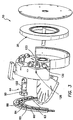
- Figs. 3 and 4 show, respectively, the device 10 in a somewhat exploded perspective view with one finger 44 pulled away from axial cam 30, and a cut-away perspective view of an individual finger 44 having various advantageous features.
- the pump finger 44 may include a tube occluder surface 88, such as a leading edge or tip member, that fully compresses the tube 50 such that the lumen of the tube 50 becomes fully closed or pinched off when the finger 44 is at or beyond a desired amount of forward advancement (e.g., when the finger 44 is within a certain distance of its maximum forward travel).
- a tube occluder surface 88 such as a leading edge or tip member
- finger 44 incorporates a transverse slot 90 through which a spring-biased occlusion element 92 extends slightly beyond a compression surface 94 of the head portion 84 of the finger 44.
- Occlusion element 92 is shown substantially centrally located within head portion 82 but other locations may also be suitable.
- the occlusion elements 92 may be located off-center, or near or at peripheral regions or ends of the compression surfaces 94.
- Occlusion element spring 96 functions to bias the occlusion element 92 to an extended position. Extension of the occlusion element 92 may be limited by occlusion element guide pins 102 disposed in or associated with apertures 104.
- the occlusion element 92 is positioned midway between opposite ends of the compression surface 94 such that on each finger 44 portions of the compression surface 94 are located on either side of the occlusion element 92. It will be appreciated, however, that in some embodiments the occlusion elements 92 may be positioned at locations other than midway between the ends of the compression surface 94.
- Finger 244 is substantially the same as finger 44, with an exception being that finger 244 does not have a movable, or spring biased occlusion element 92, but instead has a protrusion, for example, a ridge portion 106 with a surface 108 located distally of compression surface 294.
- ridge portion 106 is incorporated into the head 284 of the finger 244.
- fixed element 108 may be located at or near a periphery of the compression surface 294 rather than substantially centrally as shown. Ridge portion 106 functions to provide a focused region of occlusion as head 284 presses against tubing during operation of the device 10.
- the finger 44 may further include a retraction mechanism 112 for biasing the second portion 48 of the finger 44 away from the platen surface 22.
- the retraction mechanism 112 comprises a retraction spring 114, e.g. mounted in the pump finger 44 and held in position by positioning pin 116.
- a hooked end 118 of the retraction spring 114 extending outwardly from aperture 122, as shown for example in Figure 3 , engages a housing aperture 126 when the finger 44 is installed into the device housing 12.
- the pump device 10 operates in the following manner. Referring to Figure 2 , the direction of rotation of the cam 30 in the pumping action causes fluid to flow from the left to the right. Pump fingers 44 have their rollers 80 cooperatively engaged with the cam surface 32. Due to position of cam lobes L, the first finger and last finger, 44a and 44b respectively, are fully extended with the fingers 44 in between being progressively retracted as controlled by contours of the cam surface 32. The occlusion valve elements 92a and 92b of the first and last pump fingers 44a and 44b, operate to occlude a section of tubing 50 creating a captured volume of fluid between the first pump finger 44a and last pump finger 44b.
- the second left pump finger further extends to compress and occlude the tubing above it while at the same time the last finger retracts and removes the tubing occlusion above it.
- Fluid in the tube 50 now starts to flow to the right past the last pump finger.
- fluid from the inlet side of the tubing 50 begins to fill the tubing section behind (from the left) of the second left pump finger.
- subsequent pumping fingers progressively continue to compress and occlude the tubing above them thus causing the fluid in the tubing to flow to the right and fill from the left.
- the cam has a plurality of cam lobes, when the left lobe finally arrives under the last pump finger (right most), another cam lobe arrives under the first pump finger capturing a new volume of fluid between the first and last pump fingers 44.
- Rollers 80 or other moveable members on the fingers 44 may roll, rotate ride or otherwise ride or track through a cam surface 32 that comprises a race, such as a groove or depression.
- the shape of the roller 80 or other moveable element may correspond to the shape of the cam surface race 32 to provide for firm tracking and minimal wear of the rollers 44.
- Figures 4A-4E show several non-limiting examples of this concept.
- the cam 30a has a race surface 32a that is substantially arcuate and the rollers 80a on the fingers 44 are substantially spherical and or corresponding size such that they seat and roll firmly on the arcuate race surface 32a, as shown.
- the cam 30b has a race surface 32b that is substantially V-shaped in cross section and the rollers 80b on the fingers 44 have substantially spherical shapes and are of corresponding size such that they seat and roll firmly in the race, contacting opposite side walls of the substantially V shaped race surface 32b, as shown.
- the cam 30c has a race surface 32c that is substantially tapered on one side and the rollers 80c on the fingers 44 have a corresponding taper and size such that they seat and roll firmly in the substantially tapered race 32c, as shown.
- the cam 30d has a race surface 32d that comprises an elongate raised area (e.g., a rail, hump or bead) and the rollers 80d have corresponding grooves or indentations formed on their surfaces such that they seat and roll firmly on the race surface 32d, as shown.
- the cam 30e has a race surface 32e that is substantially flat and the fingers are maintained in positions such that they ride on the race surface 32e, as shown.
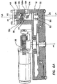
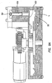
- FIG. 6A shows a finger 44 of the device 10, aligned substantially parallel to the axis of rotation of cam 30 (the axis of rotation being represented by dashed line AR in Figure 6A ).
- Wall portions 12a and 12b of the housing 12 maintain positioning of the finger 44 over the cam surface 32 of such that the roller 80 of the finger 44 is seated within the concave cam race.
- the retraction spring 114 of the finger 44 extends through the aperture 126 of the housing 12 and may rest against aperture surface 126a.
- the distal end of the occlusion valve element 92 is in contact with, but causes no substantial compression of, the fluid filled tubing 50.
- the tubing 50 is being held in place against the platen surface 22 by means rib 63.
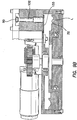
- Figure 6B shows the action of the finger 44 as it reciprocates toward the platen surface 22 as a cam lobe L passes beneath roller 80 causing occlusion valve element 92 to compress tubing 50 against the platen surface 22 and occluding fluid flow therethrough.
- the occlusion valve springs 96 functions to bias the occlusion valve element 92 to this extended position as restrained by the guide pins 102 through the apertures 104.
- the race of cam surface 32 is defined by a concavely curved transverse cross-section sized so that the roller 50 can be freely seated therein.
- the cross section of the cam race has a radius that is somewhat larger than a radius of the roller 50, in order that the roller 50 contacts the cam surface 32 at a very small region of contact, theoretically, a point of contact.
- the cam surface includes a substantially V-notch cross-sectional race, such that each of the rollers contacts the cam surface at two substantially opposing "points".
- Other configurations, such as a tapered cross sectional race may alternatively be provided.
- Figure 7 shows an alternative peristaltic pump device 210 of the invention with an integral platen and cassette assembly 216.
- This device 210 is substantially the same as device 10, with a primary difference being that device 210 includes no hinged door, latch or stop.
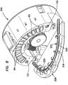
- Figure 8 shows another embodiment of a rotary axial peristaltic pump device 310 of the present invention with cassette tubing carrier structure 318 incorporated into a hinged door 328.
- a planar platen surface 330 and ribs or rib members 332 are incorporated into the door 328 as shown.
- the door 328 pivots between open and closed positions.
- pressure detection devices 132, 133 may be included in the device 10, one just prior to the first pump finger (inlet side) and the other following the last pump finger (outlet side).
- an apparatus for detecting the pressure in the tubing may be provided.
- the tubing 50 is partially compressed by the pressure detection device 132, 133 which exerts a reactive force against a preloaded strain gauge beam 133 having one end attached to the housing.
- the amount of deflection of the strain gauge beam 133 varies directly with the amount of pressure within the tubing 50 at the location of that pressure detection device 132, 133.
- Any conventional strain gauge transducer may be used. More specifically, the strain gauge beam 133 operates in the following manner.
- the tubing 50 As the pressure in the tubing 50 increases or decreases, the tubing 50 swells or contracts respectively against the fixed planar platen so as to cause the pressure detecting device 132, 133 to exert a different pressure against the strain gauge beam 133 and thereby change the strain gauge beam deflection.
- the electric signal measured from a strain gauge is proportional to the amount of deflection the strain gauge beam experiences.
- calibrating the electric signal from the strain gauge allows a system to determine the amount of pressure in the tubing for the purpose of pressure reading and occlusion detection.
- fluid is drawn into the pump tubing 50 from the inlet side. If the inflow of fluid into the pump tubing 50 becomes obstructed, for example if an inlet or supply tube is kinked, or if the source of fluid become depleted, a decrease in pressure in the tubing 50 will occur causing the tubing 50 to collapse and lessen its force against the pressure detection device 132 in the inlet side, thereby causing the strain gauge beam 133 associated with that pressure detection device 132 to deflect towards the tubing 50 as seen in Figure 9B .
- a controller, computer or processor associated with the pumping device 10 may provide an inlet occlusion alarm or signal and/or may invoke some desired remedial measure such as automatic shut down of the pumping device 10.
- a controller, computer or processor associated with the pumping device 10 may provide an inlet occlusion alarm or signal and/or may invoke some desired remedial measure such as automatic shut down of the pumping device 10.
- fluid is pushed out of the outlet end of the pump tubing 50. If the outflow of fluid from tubing 50 becomes obstructed, for example if an outlet tube is blocked or pinched off outside of the pump, an increase in pressure in the pump tubing 50 will occur, thereby causing the tubing 50 to swell.
- Such swelling of the tubing 50 causes the pressure detection device 134 at the outlet end of the pump device 10 to cause the strain gauge beam 133 associated with that pressure detection device 134 to deflect away from the tubing 50 as seen in Figure 9A . If the amount of deflection away from the tubing 50 exceeds a predetermined amount, a controller, computer or processor associated with the pumping device 10 may provide an outlet occlusion alarm or signal and/or may invoke some desired remedial measure such as automatic shut down of the pumping device 10.
Landscapes
- Engineering & Computer Science (AREA)
- Mechanical Engineering (AREA)
- General Engineering & Computer Science (AREA)
- Reciprocating Pumps (AREA)
- Infusion, Injection, And Reservoir Apparatuses (AREA)
Claims (40)
- Dispositif de pompe péristaltique (10) comprenant :un plateau (20) ayant une surface de plateau (22) ;un tube (50) positionné adjacent à la surface de plateau ;une came (30, 30a) qui tourne autour d'un axe de rotation (AR), ladite came ayant une surface de came (32) qui est espacée de la surface de plateau ; etune pluralité de doigts (44), chaque doigt ayant une première partie en enclenchement coopératif avec la surface de came, une seconde partie adjacente à la surface de plateau, un ressort (114) pour pousser le doigt dans une direction en éloignement de la surface de plateau et un axe longitudinal (LA) qui est sensiblement parallèle à l'axe de rotation de la came, lesdits doigts étant en enclenchement avec la surface de came de sorte que, lorsque la came tourne autour de l'axe de rotation, les doigts se déplaceront axialement d'avant en arrière, comprimant séquentiellement le tube contre la surface de plateau et provoquant ainsi un déplacement péristaltique de fluide à travers le tube ; caractérisé parune trappe (14) qui peut être ouverte et fermée pour permettre un accès au tube ;
dans lequel :le tube est monté sur ou dans une cassette (60) et la trappe peut être ouverte pour gagner accès afin de permettre le retrait de la cassette sur ou dans laquelle se trouve le tube et son remplacement par une autre cassette sur ou dans laquelle se trouve un autre tube,au moins une surface d'alignement est formée dans la trappe, ladite surface d'alignement étant configurée pour s'aligner avec la cassette lorsque la trappe est fermée, maintenant ainsi la cassette dans un alignement souhaité, etla surface de plateau est prévue sur une surface intérieure de la trappe et au moins une indentation est formée dans ladite surface de plateau de sorte que le tube sera sensiblement juxtaposé à la surface de plateau lorsque la trappe est fermée. - Dispositif selon la revendication 1, dans lequel la surface de plateau (22) est sensiblement plane.
- Dispositif selon la revendication 1, dans lequel la surface de came (32) comporte une pluralité de lobes (L).
- Dispositif selon la revendication 3, dans lequel chaque lobe (L) de la came (30) comprend une vague dans la surface de came (32), chacune de ces vagues ayant une crête, la crête de chaque vague étant plus proche de la surface de plateau (22) que le reste de la surface de came.
- Dispositif selon la revendication 1, dans lequel chaque doigt (44) comprend en outre un second ressort (96) pour pousser le doigt en contact avec le tube (50).
- Dispositif selon la revendication 1, dans lequel la surface de plateau (22) est sensiblement plate.
- Dispositif selon la revendication 1, dans lequel la trappe (14) est raccordée en pivotement à un boîtier (12) du dispositif de pompe (10).
- Dispositif selon la revendication 1, dans lequel la surface de plateau (22) est située sur un côté de la trappe (14).
- Dispositif selon la revendication 1, dans lequel la cassette (60) comprend une pluralité d'encoches de réception de tube (65) au sein desquelles le tube (50) est reçu.
- Dispositif selon la revendication 9, dans lequel la surface de plateau (22) est sensiblement plate et la cassette (60) maintient le tube (50) adjacent à la surface de plateau sensiblement plate.
- Dispositif selon la revendication 1, dans lequel le boîtier (12) comporte un loquet (72).
- Dispositif selon la revendication 1, comprenant en outre un boîtier (12) avec un orifice (126) à travers lequel le ressort (114) s'étend.
- Dispositif selon la revendication 1, dans lequel chaque doigt (44) incorpore un élément de bout sollicité par ressort (92) sur son extrémité.
- Dispositif selon la revendication 13, dans lequel une extension de l'élément de bout (92) est limitée par des broches de guidage (102) associées à des orifices (104).
- Dispositif selon la revendication 1, dans lequel la cassette de tube (60) comprend une structure sensiblement rigide (61) qui maintient le tube (50) dans une configuration souhaitée.
- Dispositif selon la revendication 15, dans lequel la structure de cassette (61) maintient le tube (50) dans une configuration sensiblement arquée.
- Dispositif selon la revendication 1, dans lequel la surface de came (32) est située sur une région périphérique de la came (30).
- Dispositif selon la revendication 1, dans lequel la surface de came (32) comporte une surface de piste sensiblement plate, concave ou convexe (32a à e).
- Dispositif selon la revendication 18, dans lequel la piste (32b) comprend une gorge ayant une paroi sensiblement arquée.
- Dispositif selon la revendication 18, dans lequel la piste comprend une gorge ayant une paroi sensiblement en forme de V.
- Dispositif selon la revendication 18, dans lequel la piste (32c) comprend une gorge ayant une paroi sensiblement effilée.
- Dispositif selon la revendication 18, dans lequel la piste (32d) comprend une zone relevée sur la came (30, 30a).
- Dispositif selon la revendication 18, dans lequel les doigts (44) ont des galets (80a à d) qui courent sur ou dans la piste (32a à e)
- Dispositif selon la revendication 19, dans lequel les doigts (44) ont des galets sensiblement sphériques (80a) qui courent contre la paroi sensiblement arquée.
- Dispositif selon la revendication 20, dans lequel les doigts (44) ont des galets (80b) qui courent contre des emplacements sur des côtés opposés de la paroi sensiblement en forme de V.
- Dispositif selon la revendication 21, dans lequel les doigts (44) ont des galets (80c) qui courent contre la paroi sensiblement effilée.
- Dispositif selon la revendication 22, dans lequel les doigts (44) ont de galets (80d) qui sont configurés pour courir sur la zone relevée.
- Dispositif selon la revendication 18, dans lequel un plan axial est projetable à travers la piste (32a à e), ledit plan axial étant sensiblement perpendiculaire à l'axe de rotation (AR) autour duquel la came (30, 30a) tourne.
- Dispositif selon la revendication 1, dans lequel au moins l'un des doigts (44) comporte un élément d'occlusion (92) qui comprime le tube (50) suffisamment pour obstruer sensiblement la lumière de tube pendant une partie du cycle de pompage.
- Dispositif selon la revendication 29, dans lequel le doigt (44) a une surface de compression de tube (94) d'une première largeur et l'élément d'occlusion de tube (92) dépasse au-delà de la surface de compression de tube, ledit élément d'occlusion de tube ayant une seconde largeur qui est inférieure à ladite première largeur.
- Dispositif selon la revendication 29, dans lequel chaque doigt (44) a un point de déplacement maximal où l'élément d'occlusion (92) est aussi proche que possible de la surface de plateau (22), et dans lequel chaque élément d'occlusion est sollicité par ressort de façon à exercer une quantité régulée de force de compression sur le tube (50) lorsque ce doigt est à ou à moins d'une distance prédéterminée de son point de déplacement maximal.
- Dispositif selon la revendication 29, dans lequel une fente transversale (90) est formée dans le doigt de pompe (44) et l'élément d'occlusion (92) est disposé en coulissement au sein de cette fente transversale.
- Dispositif selon la revendication 32, dans lequel le doigt de pompe (44) comprend en outre un ressort (96) qui pousse l'élément d'occlusion (92) dans une position étendue.
- Dispositif selon la revendication 1, comprenant en outre un dispositif de régulation pour réguler le fonctionnement du dispositif (10).
- Dispositif selon la revendication 1, dans lequel la cassette de tube (60) incorpore une particularité d'identification qui est identifiable par le dispositif de pompage (10).
- Dispositif selon la revendication 34, dans lequel la cassette de tube (60) incorpore une particularité d'identification qui est identifiable par le dispositif de régulation et dans lequel le dispositif de régulation est programmé pour prévenir un fonctionnement du dispositif (10) avec des cassettes qui n'incorporent pas une particularité d'identification acceptable.
- Procédé de pompage de fluide, ledit procédé comprenant les étapes de :A) fourniture d'un dispositif de pompe péristaltique qui comporte : i) un plateau (20) ayant une surface de plateau (22), ii) un tube (50) positionné adjacent à la surface de plateau, iii) une came (30, 30a) qui tourne autour d'un axe de rotation (AR), ladite came ayant une surface de came (32) qui est espacée de la surface de plateau, iv) une pluralité de doigts (44), chaque doigt ayant une première partie en enclenchement coopératif avec la surface de came, une seconde partie adjacente à la surface de plateau, un ressort (114) pour pousser le doigt dans une direction en éloignement de la surface de plateau et un axe longitudinal (LA) qui est sensiblement parallèle à l'axe de rotation de la came, lesdits doigts étant en enclenchement coopératif avec la surface de came de sorte qu'une rotation de la came autour de l'axe de rotation amènera les doigts à se déplacer d'avant en arrière, sur leurs axes longitudinaux, comprimant ainsi séquentiellement le tube contre la surface de plateau et aboutissant à un déplacement péristaltique de fluide à travers le tube, v) une trappe (14) configurée pour s'ouvrir et se fermer afin de permettre un accès au tube, la surface de plateau se trouvant sur une surface intérieure de la trappe, vi) une cassette (60), dans lequel le tube est monté sur ou dans la cassette, vii) au moins une surface d'alignement formée dans la trappe, et viii) au moins une indentation formée dans la surface de plateau ;B) fixation d'une extrémité du tube à une source de fluide ;C) fermeture de la trappe de sorte que l'au moins une surface d'alignement s'aligne avec la cassette pour maintenir la cassette dans un alignement souhaité, et l'au moins une indentation formée dans la surface de plateau amène le tube à être sensiblement juxtaposé à la surface de plateau ; etD) rotation de la came de sorte que les doigts compriment séquentiellement le tube contre la surface de plateau, provoquant ainsi un déplacement péristaltique du fluide à travers le tube.
- Procédé selon la revendication 37, dans lequel la trappe (14) est articulée à un boîtier (12) du dispositif de pompe (10).
- Procédé selon la revendication 37, dans lequel le boîtier (12) comporte un loquet (72), le procédé comprenant en outre l'étape d'activation d'ouverture de la trappe (14) en soulevant le loquet.
- Procédé selon la revendication 37, comprenant en outre l'étape de retrait et de remplacement de la cassette de tube (60).
Applications Claiming Priority (2)
| Application Number | Priority Date | Filing Date | Title |
|---|---|---|---|
| US11/212,931 US7556481B2 (en) | 2005-08-26 | 2005-08-26 | Rotary axial peristaltic pumps and related methods |
| PCT/US2006/033609 WO2007025268A2 (fr) | 2005-08-26 | 2006-08-25 | Pompes péristaltiques axiales rotatives et procédés associés |
Publications (3)
| Publication Number | Publication Date |
|---|---|
| EP1917439A2 EP1917439A2 (fr) | 2008-05-07 |
| EP1917439A4 EP1917439A4 (fr) | 2010-04-28 |
| EP1917439B1 true EP1917439B1 (fr) | 2017-04-12 |
Family
ID=37772518
Family Applications (1)
| Application Number | Title | Priority Date | Filing Date |
|---|---|---|---|
| EP06790047.2A Not-in-force EP1917439B1 (fr) | 2005-08-26 | 2006-08-25 | Pompes péristaltiques axiales rotatives et procédés associés |
Country Status (12)
| Country | Link |
|---|---|
| US (5) | US7556481B2 (fr) |
| EP (1) | EP1917439B1 (fr) |
| JP (2) | JP5241495B2 (fr) |
| CN (1) | CN101454571B (fr) |
| AU (1) | AU2006282818B2 (fr) |
| BR (1) | BRPI0615090A2 (fr) |
| CA (1) | CA2620561C (fr) |
| ES (1) | ES2632151T3 (fr) |
| MX (1) | MX2008002725A (fr) |
| NZ (1) | NZ565948A (fr) |
| WO (1) | WO2007025268A2 (fr) |
| ZA (1) | ZA200801458B (fr) |
Families Citing this family (42)
| Publication number | Priority date | Publication date | Assignee | Title |
|---|---|---|---|---|
| US20030074223A1 (en) * | 2001-09-24 | 2003-04-17 | Scott Laboratories, Inc. | Methods and apparatuses for assuring quality and safety of drug administration and medical products and kits |
| US8308457B2 (en) | 2004-11-24 | 2012-11-13 | Q-Core Medical Ltd. | Peristaltic infusion pump with locking mechanism |
| IL165365A0 (en) | 2004-11-24 | 2006-01-15 | Q Core Ltd | Finger-type peristaltic pump |
| US7556481B2 (en) * | 2005-08-26 | 2009-07-07 | Baxter International Inc. | Rotary axial peristaltic pumps and related methods |
| WO2008032341A1 (fr) * | 2006-09-11 | 2008-03-20 | Cembre S.P.A. | Outil de presse et/ou de découpe hydraulique et mécanisme de conversion d'un mouvement rotatif en mouvement oscillant en translation pour cet outil |
| IL179234A0 (en) | 2006-11-13 | 2007-03-08 | Q Core Ltd | An anti-free flow mechanism |
| US8535025B2 (en) | 2006-11-13 | 2013-09-17 | Q-Core Medical Ltd. | Magnetically balanced finger-type peristaltic pump |
| IL179231A0 (en) | 2006-11-13 | 2007-03-08 | Q Core Ltd | A finger-type peristaltic pump comprising a ribbed anvil |
| US8303275B2 (en) * | 2006-12-07 | 2012-11-06 | Seiko Epson Corporation | Micropump, tube unit, and control unit |
| US8062008B2 (en) * | 2007-09-27 | 2011-11-22 | Curlin Medical Inc. | Peristaltic pump and removable cassette therefor |
| US7934912B2 (en) * | 2007-09-27 | 2011-05-03 | Curlin Medical Inc | Peristaltic pump assembly with cassette and mounting pin arrangement |
| US8083503B2 (en) | 2007-09-27 | 2011-12-27 | Curlin Medical Inc. | Peristaltic pump assembly and regulator therefor |
| US8215931B2 (en) * | 2008-07-14 | 2012-07-10 | Blue-White Industries, Ltd. | Safety switch on a peristaltic pump |
| JP5298699B2 (ja) * | 2008-08-20 | 2013-09-25 | セイコーエプソン株式会社 | 制御ユニット、チューブユニット、マイクロポンプ |
| JP5282508B2 (ja) * | 2008-09-29 | 2013-09-04 | セイコーエプソン株式会社 | 制御ユニット、チューブユニット、マイクロポンプ |
| JP5195368B2 (ja) | 2008-12-05 | 2013-05-08 | セイコーエプソン株式会社 | チューブユニット、制御ユニット、マイクロポンプ |
| US8371832B2 (en) * | 2009-12-22 | 2013-02-12 | Q-Core Medical Ltd. | Peristaltic pump with linear flow control |
| US9457158B2 (en) | 2010-04-12 | 2016-10-04 | Q-Core Medical Ltd. | Air trap for intravenous pump |
| WO2012095829A2 (fr) | 2011-01-16 | 2012-07-19 | Q-Core Medical Ltd. | Méthodes, appareil et systèmes de communication, commande et localisation d'un dispositif médical |
| EP3536361B1 (fr) | 2011-03-23 | 2020-10-07 | NxStage Medical Inc. | Systèmes, dispositifs et procédés de dialyse péritonéale |
| US9861733B2 (en) | 2012-03-23 | 2018-01-09 | Nxstage Medical Inc. | Peritoneal dialysis systems, devices, and methods |
| JP5857466B2 (ja) * | 2011-06-20 | 2016-02-10 | セイコーエプソン株式会社 | 流体輸送装置 |
| WO2013001425A2 (fr) | 2011-06-27 | 2013-01-03 | Q-Core Medical Ltd. | Procédés, circuits, dispositifs, appareils, boîtiers et systèmes pour identifier un déréglage d'un système de perfusion médical |
| JP5861341B2 (ja) | 2011-09-12 | 2016-02-16 | 頴 小西 | ポンプ装置 |
| JP5982855B2 (ja) * | 2012-02-17 | 2016-08-31 | セイコーエプソン株式会社 | 流体輸送装置、交換ユニット、及び交換ユニットの製造方法 |
| CN102705191B (zh) * | 2012-06-01 | 2015-09-23 | 沈如华 | 调色机的色浆定量供应装置 |
| JP6102094B2 (ja) * | 2012-06-26 | 2017-03-29 | セイコーエプソン株式会社 | 流体輸送装置、流体輸送装置の交換ユニット、流体輸送装置の本体ユニット、および流体輸送装置の交換ユニットの製造方法 |
| JP2014084753A (ja) * | 2012-10-22 | 2014-05-12 | Seiko Epson Corp | 流体注入装置 |
| JP5956920B2 (ja) * | 2012-12-14 | 2016-07-27 | 株式会社コガネイ | 液体供給装置 |
| US9855110B2 (en) | 2013-02-05 | 2018-01-02 | Q-Core Medical Ltd. | Methods, apparatus and systems for operating a medical device including an accelerometer |
| EP2792893B1 (fr) * | 2013-04-19 | 2016-02-10 | Aktiebolaget SKF | Cage à poches parallèles pour palier à roulement |
| CN104147658B (zh) * | 2013-05-15 | 2017-03-22 | 深圳市深科医疗器械技术开发有限公司 | 输液泵 |
| WO2014201358A2 (fr) | 2013-06-14 | 2014-12-18 | Bayer Medical Care Inc. | Système portable de distribution de fluide |
| US10549084B2 (en) | 2014-01-10 | 2020-02-04 | Bayer Healthcare Llc | Single-use disposable set connector |
| CA2973257C (fr) | 2015-01-09 | 2023-09-19 | Bayer Healthcare Llc | Systeme multiple de distribution de fluide avec ensemble jetable a usages multiples et caracteristiques de celui-ci |
| WO2017218372A1 (fr) | 2016-06-15 | 2017-12-21 | Bayer Healthcare Llc | Système jetable à usages multiples et seringue associée |
| WO2019169081A2 (fr) | 2018-02-28 | 2019-09-06 | Nxstage Medical, Inc. | Dispositifs, procédés et systèmes de préparation de fluide et de traitement |
| US11007308B2 (en) * | 2018-10-24 | 2021-05-18 | Misonix, Incorporated | Fluid handling assembly and related tube set and method for use in surgical procedures |
| US10808689B2 (en) | 2018-12-17 | 2020-10-20 | Curlin Medical Inc. | Peristaltic pump having improved pumping fingers |
| US11679189B2 (en) | 2019-11-18 | 2023-06-20 | Eitan Medical Ltd. | Fast test for medical pump |
| US11957365B2 (en) | 2020-11-20 | 2024-04-16 | Covidien Lp | Aspiration pulsator |
| CN113350013B (zh) * | 2021-07-21 | 2022-11-08 | 中国人民解放军陆军特色医学中心 | 一种加强型阴囊背带裤 |
Family Cites Families (44)
| Publication number | Priority date | Publication date | Assignee | Title |
|---|---|---|---|---|
| CH503A (de) | 1889-02-27 | 1889-04-02 | Hermann Bloechlinger Ulrich | Den Soldaten gegen Säbelhiebe, Lanzen- und Bajonnetstiche sichern Schutz bietender Brustpanzer |
| US1933081A (en) * | 1931-05-20 | 1933-10-31 | Stephan Engineering Corp | Fuel supply system |
| US2752852A (en) * | 1954-09-29 | 1956-07-03 | Standard Oil Co | Variable displacement pump |
| US2877714A (en) | 1957-10-30 | 1959-03-17 | Standard Oil Co | Variable displacement tubing pump |
| US3172367A (en) | 1963-01-08 | 1965-03-09 | Technicon Instr | Roller type pump |
| CH503202A (de) | 1969-02-06 | 1971-02-15 | Erard Etienne | Flüssigkeitspumpvorrichtung |
| DE2152352A1 (de) | 1971-10-21 | 1973-04-26 | Bodenseewerk Perkin Elmer Co | Schlauchpumpe |
| US3901565A (en) | 1973-09-12 | 1975-08-26 | Magnus F Hagen | Adaptor and latching means for removably attaching drawers to telescoping ball bearing drawer slides |
| US4004377A (en) * | 1974-05-06 | 1977-01-25 | Laudick Richard D | Machine for forming a locator pin |
| SU853157A1 (ru) | 1979-11-13 | 1981-08-07 | Предприятие П/Я М-5534 | Перистальтический насос |
| US4626940A (en) * | 1982-06-07 | 1986-12-02 | Olympus Optical Co., Ltd. | Tape recorder with reciprocating magnetic heads |
| DE3227051A1 (de) * | 1982-07-20 | 1984-02-02 | B. Braun Melsungen Ag, 3508 Melsungen | Schlauchpumpe, insbesondere fuer medizinische anwendungen |
| US4558996A (en) * | 1983-06-30 | 1985-12-17 | Organon Teknika Corporation | Easy load peristaltic pump |
| US4671792A (en) | 1986-02-18 | 1987-06-09 | American Hospital Supply Corporation | Pressure-regulating peristaltic pump |
| SU1366693A1 (ru) | 1986-04-09 | 1988-01-15 | Березниковский филиал Всесоюзного научно-исследовательского и проектного института титана | Перистальтический насос |
| US4728265A (en) | 1987-01-30 | 1988-03-01 | Fisher Scientific Group Inc. | Peristaltic pump with cam action compensator |
| US4753581A (en) * | 1987-02-10 | 1988-06-28 | Milton Roy Company | Constant suction pump for high performance liquid chromatography |
| US4893991A (en) | 1987-05-27 | 1990-01-16 | Heminway James F | Method and means for improving efficiency of peristaltic pumps |
| US4886431A (en) | 1988-04-29 | 1989-12-12 | Cole-Parmer Instrument Company | Peristaltic pump having independently adjustable cartridges |
| JPH04295183A (ja) * | 1991-03-22 | 1992-10-20 | Jidosha Kiki Co Ltd | アキシャルピストンポンプ |
| FR2690621B1 (fr) * | 1992-04-29 | 1995-02-10 | Chronotec | Système de pompe à perfusion sans frottements. |
| US5626563A (en) * | 1993-01-12 | 1997-05-06 | Minnesota Mining And Manufacturing Company | Irrigation system with tubing cassette |
| US5482446A (en) * | 1994-03-09 | 1996-01-09 | Baxter International Inc. | Ambulatory infusion pump |
| US5733105A (en) * | 1995-03-20 | 1998-03-31 | Micropump, Inc. | Axial cam driven valve arrangement for an axial cam driven parallel piston pump system |
| WO1997029285A1 (fr) * | 1996-02-09 | 1997-08-14 | Allan R Jones Technologies Pty. Limited | Mecanisme de pompe peristaltique |
| US5791881A (en) | 1996-10-18 | 1998-08-11 | Moubayed; Ahmad-Maher | Curvilinear peristaltic pump with occlusion detection means |
| AU719693B2 (en) * | 1996-03-12 | 2000-05-18 | Curlin Medical Inc. | Peristaltic pump with pinch fingers for providing complete occlusion |
| US5924852A (en) * | 1996-03-12 | 1999-07-20 | Moubayed; Ahmad-Maher | Linear peristaltic pump |
| US6036459A (en) | 1996-04-04 | 2000-03-14 | Medtronic, Inc. | Occlusion compensator for implantable peristaltic pump |
| US5840069A (en) * | 1996-04-04 | 1998-11-24 | Medtronic, Inc. | Implantable peristaltic pump techniques |
| US5879144A (en) * | 1996-08-14 | 1999-03-09 | Sims Deltec, Inc. | Pressure plate adaptors and methods |
| US5752813A (en) * | 1996-10-23 | 1998-05-19 | A.Z.E. Medical Inc. | Keyed cassette for dispensing pump |
| GR1002892B (el) * | 1997-02-17 | 1998-04-10 | Micrel | Γραμμικη περισταλτικη αντλια |
| US6164921A (en) * | 1998-11-09 | 2000-12-26 | Moubayed; Ahmad Maher | Curvilinear peristaltic pump having insertable tubing assembly |
| JP2001073954A (ja) * | 1999-09-03 | 2001-03-21 | Toshin Akutsu | チューブポンプ |
| US6296460B1 (en) * | 2000-03-01 | 2001-10-02 | Steve C. Smith | Rotary cavity pump |
| JP4834216B2 (ja) | 2000-10-25 | 2011-12-14 | 株式会社三共製作所 | カム装置 |
| US7029414B2 (en) | 2001-05-11 | 2006-04-18 | The Timken Company | Hub assembly with speed change |
| DE10244090A1 (de) * | 2002-09-23 | 2004-04-01 | Ismatec S.A. | Schlauchkassette für eine peristaltische Pumpe |
| US7150607B2 (en) * | 2002-11-18 | 2006-12-19 | International Remote Imaging Systems, Inc. | Uniform flow displacement pump |
| US7223079B2 (en) * | 2003-07-28 | 2007-05-29 | The Coca-Cola Company | Quick loading peristaltic pump |
| JP2005083299A (ja) * | 2003-09-10 | 2005-03-31 | Toyota Motor Corp | 内燃機関の潤滑油供給装置 |
| US7273359B2 (en) * | 2003-11-05 | 2007-09-25 | Linvatec Corporation | Peristaltic irrigation pump system |
| US7556481B2 (en) * | 2005-08-26 | 2009-07-07 | Baxter International Inc. | Rotary axial peristaltic pumps and related methods |
-
2005
- 2005-08-26 US US11/212,931 patent/US7556481B2/en not_active Expired - Fee Related
-
2006
- 2006-05-19 US US11/437,575 patent/US7762795B2/en active Active
- 2006-05-19 US US11/437,269 patent/US20080101967A1/en not_active Abandoned
- 2006-05-19 US US11/437,274 patent/US8308456B2/en not_active Expired - Fee Related
- 2006-08-25 AU AU2006282818A patent/AU2006282818B2/en not_active Ceased
- 2006-08-25 CN CN2006800312191A patent/CN101454571B/zh not_active Expired - Fee Related
- 2006-08-25 NZ NZ565948A patent/NZ565948A/en not_active IP Right Cessation
- 2006-08-25 EP EP06790047.2A patent/EP1917439B1/fr not_active Not-in-force
- 2006-08-25 MX MX2008002725A patent/MX2008002725A/es active IP Right Grant
- 2006-08-25 CA CA2620561A patent/CA2620561C/fr not_active Expired - Fee Related
- 2006-08-25 WO PCT/US2006/033609 patent/WO2007025268A2/fr active Application Filing
- 2006-08-25 BR BRPI0615090-0A patent/BRPI0615090A2/pt not_active IP Right Cessation
- 2006-08-25 JP JP2008528242A patent/JP5241495B2/ja not_active Expired - Fee Related
- 2006-08-25 ES ES06790047.2T patent/ES2632151T3/es active Active
-
2008
- 2008-02-13 ZA ZA200801458A patent/ZA200801458B/xx unknown
-
2009
- 2009-04-15 US US12/424,067 patent/US8297954B2/en not_active Expired - Fee Related
-
2012
- 2012-02-15 JP JP2012030663A patent/JP2012122483A/ja not_active Withdrawn
Non-Patent Citations (1)
| Title |
|---|
| None * |
Also Published As
| Publication number | Publication date |
|---|---|
| JP5241495B2 (ja) | 2013-07-17 |
| US8308456B2 (en) | 2012-11-13 |
| US20090196776A1 (en) | 2009-08-06 |
| EP1917439A4 (fr) | 2010-04-28 |
| CN101454571A (zh) | 2009-06-10 |
| ES2632151T3 (es) | 2017-09-11 |
| US20080101969A1 (en) | 2008-05-01 |
| US20070048161A1 (en) | 2007-03-01 |
| JP2009509078A (ja) | 2009-03-05 |
| WO2007025268A2 (fr) | 2007-03-01 |
| WO2007025268A3 (fr) | 2009-01-08 |
| AU2006282818B2 (en) | 2011-03-31 |
| AU2006282818A1 (en) | 2007-03-01 |
| US7762795B2 (en) | 2010-07-27 |
| US20080101968A1 (en) | 2008-05-01 |
| US8297954B2 (en) | 2012-10-30 |
| EP1917439A2 (fr) | 2008-05-07 |
| BRPI0615090A2 (pt) | 2011-05-03 |
| CN101454571B (zh) | 2012-01-04 |
| JP2012122483A (ja) | 2012-06-28 |
| CA2620561A1 (fr) | 2007-03-01 |
| ZA200801458B (en) | 2009-03-25 |
| US7556481B2 (en) | 2009-07-07 |
| NZ565948A (en) | 2010-02-26 |
| US20080101967A1 (en) | 2008-05-01 |
| MX2008002725A (es) | 2008-03-26 |
| CA2620561C (fr) | 2014-07-15 |
Similar Documents
| Publication | Publication Date | Title |
|---|---|---|
| EP1917439B1 (fr) | Pompes péristaltiques axiales rotatives et procédés associés | |
| US5791881A (en) | Curvilinear peristaltic pump with occlusion detection means | |
| EP0886729B1 (fr) | Pompe peristaltique a doigts de contact assurant l'occlusion complete | |
| US5217355A (en) | Two-cycle peristaltic pump with occlusion detector | |
| US5575631A (en) | Curvilinear peristaltic pump | |
| US5683233A (en) | Non-rolling type peristaltic pump having pressure plate mounted tube biasing means | |
| US5924852A (en) | Linear peristaltic pump | |
| US9470220B2 (en) | Pump module, pump base module and pump system | |
| US20030214412A1 (en) | Proper tubing installation testing method and apparatus for a peristaltic pump | |
| US5419684A (en) | Infusion pump with reversible motor and method of use |
Legal Events
| Date | Code | Title | Description |
|---|---|---|---|
| PUAI | Public reference made under article 153(3) epc to a published international application that has entered the european phase |
Free format text: ORIGINAL CODE: 0009012 |
|
| 17P | Request for examination filed |
Effective date: 20080222 |
|
| AK | Designated contracting states |
Kind code of ref document: A2 Designated state(s): AT BE BG CH CY CZ DE DK EE ES FI FR GB GR HU IE IS IT LI LT LU LV MC NL PL PT RO SE SI SK TR |
|
| AX | Request for extension of the european patent |
Extension state: AL BA HR MK RS |
|
| R17D | Deferred search report published (corrected) |
Effective date: 20090108 |
|
| RAP1 | Party data changed (applicant data changed or rights of an application transferred) |
Owner name: BAXTER INTERNATIONAL INC. Owner name: BAXTER HEALTHCARE S.A. |
|
| A4 | Supplementary search report drawn up and despatched |
Effective date: 20100331 |
|
| RIC1 | Information provided on ipc code assigned before grant |
Ipc: F04B 43/08 20060101AFI20100325BHEP |
|
| 17Q | First examination report despatched |
Effective date: 20100727 |
|
| DAX | Request for extension of the european patent (deleted) | ||
| REG | Reference to a national code |
Ref country code: DE Ref legal event code: R079 Ref document number: 602006052250 Country of ref document: DE Free format text: PREVIOUS MAIN CLASS: F04B0043120000 Ipc: F04B0043080000 |
|
| GRAP | Despatch of communication of intention to grant a patent |
Free format text: ORIGINAL CODE: EPIDOSNIGR1 |
|
| RIC1 | Information provided on ipc code assigned before grant |
Ipc: F04B 43/12 20060101ALI20161007BHEP Ipc: F04B 43/08 20060101AFI20161007BHEP |
|
| INTG | Intention to grant announced |
Effective date: 20161026 |
|
| STAA | Information on the status of an ep patent application or granted ep patent |
Free format text: STATUS: GRANT OF PATENT IS INTENDED |
|
| GRAS | Grant fee paid |
Free format text: ORIGINAL CODE: EPIDOSNIGR3 |
|
| GRAA | (expected) grant |
Free format text: ORIGINAL CODE: 0009210 |
|
| STAA | Information on the status of an ep patent application or granted ep patent |
Free format text: STATUS: THE PATENT HAS BEEN GRANTED |
|
| AK | Designated contracting states |
Kind code of ref document: B1 Designated state(s): AT BE BG CH CY CZ DE DK EE ES FI FR GB GR HU IE IS IT LI LT LU LV MC NL PL PT RO SE SI SK TR |
|
| REG | Reference to a national code |
Ref country code: GB Ref legal event code: FG4D |
|
| REG | Reference to a national code |
Ref country code: CH Ref legal event code: EP |
|
| REG | Reference to a national code |
Ref country code: IE Ref legal event code: FG4D |
|
| REG | Reference to a national code |
Ref country code: AT Ref legal event code: REF Ref document number: 884191 Country of ref document: AT Kind code of ref document: T Effective date: 20170515 |
|
| REG | Reference to a national code |
Ref country code: DE Ref legal event code: R096 Ref document number: 602006052250 Country of ref document: DE |
|
| REG | Reference to a national code |
Ref country code: NL Ref legal event code: MP Effective date: 20170412 |
|
| REG | Reference to a national code |
Ref country code: LT Ref legal event code: MG4D Ref country code: FR Ref legal event code: PLFP Year of fee payment: 12 |
|
| REG | Reference to a national code |
Ref country code: ES Ref legal event code: FG2A Ref document number: 2632151 Country of ref document: ES Kind code of ref document: T3 Effective date: 20170911 |
|
| REG | Reference to a national code |
Ref country code: AT Ref legal event code: MK05 Ref document number: 884191 Country of ref document: AT Kind code of ref document: T Effective date: 20170412 |
|
| PG25 | Lapsed in a contracting state [announced via postgrant information from national office to epo] |
Ref country code: NL Free format text: LAPSE BECAUSE OF FAILURE TO SUBMIT A TRANSLATION OF THE DESCRIPTION OR TO PAY THE FEE WITHIN THE PRESCRIBED TIME-LIMIT Effective date: 20170412 |
|
| PG25 | Lapsed in a contracting state [announced via postgrant information from national office to epo] |
Ref country code: GR Free format text: LAPSE BECAUSE OF FAILURE TO SUBMIT A TRANSLATION OF THE DESCRIPTION OR TO PAY THE FEE WITHIN THE PRESCRIBED TIME-LIMIT Effective date: 20170713 Ref country code: AT Free format text: LAPSE BECAUSE OF FAILURE TO SUBMIT A TRANSLATION OF THE DESCRIPTION OR TO PAY THE FEE WITHIN THE PRESCRIBED TIME-LIMIT Effective date: 20170412 Ref country code: LT Free format text: LAPSE BECAUSE OF FAILURE TO SUBMIT A TRANSLATION OF THE DESCRIPTION OR TO PAY THE FEE WITHIN THE PRESCRIBED TIME-LIMIT Effective date: 20170412 Ref country code: FI Free format text: LAPSE BECAUSE OF FAILURE TO SUBMIT A TRANSLATION OF THE DESCRIPTION OR TO PAY THE FEE WITHIN THE PRESCRIBED TIME-LIMIT Effective date: 20170412 |
|
| PGFP | Annual fee paid to national office [announced via postgrant information from national office to epo] |
Ref country code: NO Payment date: 20170530 Year of fee payment: 7 Ref country code: ES Payment date: 20170901 Year of fee payment: 12 Ref country code: IT Payment date: 20170823 Year of fee payment: 12 |
|
| PG25 | Lapsed in a contracting state [announced via postgrant information from national office to epo] |
Ref country code: IS Free format text: LAPSE BECAUSE OF FAILURE TO SUBMIT A TRANSLATION OF THE DESCRIPTION OR TO PAY THE FEE WITHIN THE PRESCRIBED TIME-LIMIT Effective date: 20170812 Ref country code: PL Free format text: LAPSE BECAUSE OF FAILURE TO SUBMIT A TRANSLATION OF THE DESCRIPTION OR TO PAY THE FEE WITHIN THE PRESCRIBED TIME-LIMIT Effective date: 20170412 Ref country code: LV Free format text: LAPSE BECAUSE OF FAILURE TO SUBMIT A TRANSLATION OF THE DESCRIPTION OR TO PAY THE FEE WITHIN THE PRESCRIBED TIME-LIMIT Effective date: 20170412 Ref country code: SE Free format text: LAPSE BECAUSE OF FAILURE TO SUBMIT A TRANSLATION OF THE DESCRIPTION OR TO PAY THE FEE WITHIN THE PRESCRIBED TIME-LIMIT Effective date: 20170412 Ref country code: BG Free format text: LAPSE BECAUSE OF FAILURE TO SUBMIT A TRANSLATION OF THE DESCRIPTION OR TO PAY THE FEE WITHIN THE PRESCRIBED TIME-LIMIT Effective date: 20170712 |
|
| REG | Reference to a national code |
Ref country code: DE Ref legal event code: R097 Ref document number: 602006052250 Country of ref document: DE |
|
| PG25 | Lapsed in a contracting state [announced via postgrant information from national office to epo] |
Ref country code: RO Free format text: LAPSE BECAUSE OF FAILURE TO SUBMIT A TRANSLATION OF THE DESCRIPTION OR TO PAY THE FEE WITHIN THE PRESCRIBED TIME-LIMIT Effective date: 20170412 Ref country code: EE Free format text: LAPSE BECAUSE OF FAILURE TO SUBMIT A TRANSLATION OF THE DESCRIPTION OR TO PAY THE FEE WITHIN THE PRESCRIBED TIME-LIMIT Effective date: 20170412 Ref country code: DK Free format text: LAPSE BECAUSE OF FAILURE TO SUBMIT A TRANSLATION OF THE DESCRIPTION OR TO PAY THE FEE WITHIN THE PRESCRIBED TIME-LIMIT Effective date: 20170412 Ref country code: SK Free format text: LAPSE BECAUSE OF FAILURE TO SUBMIT A TRANSLATION OF THE DESCRIPTION OR TO PAY THE FEE WITHIN THE PRESCRIBED TIME-LIMIT Effective date: 20170412 Ref country code: CZ Free format text: LAPSE BECAUSE OF FAILURE TO SUBMIT A TRANSLATION OF THE DESCRIPTION OR TO PAY THE FEE WITHIN THE PRESCRIBED TIME-LIMIT Effective date: 20170412 |
|
| PLBE | No opposition filed within time limit |
Free format text: ORIGINAL CODE: 0009261 |
|
| STAA | Information on the status of an ep patent application or granted ep patent |
Free format text: STATUS: NO OPPOSITION FILED WITHIN TIME LIMIT |
|
| 26N | No opposition filed |
Effective date: 20180115 |
|
| REG | Reference to a national code |
Ref country code: CH Ref legal event code: PL |
|
| PG25 | Lapsed in a contracting state [announced via postgrant information from national office to epo] |
Ref country code: MC Free format text: LAPSE BECAUSE OF FAILURE TO SUBMIT A TRANSLATION OF THE DESCRIPTION OR TO PAY THE FEE WITHIN THE PRESCRIBED TIME-LIMIT Effective date: 20170412 |
|
| PG25 | Lapsed in a contracting state [announced via postgrant information from national office to epo] |
Ref country code: LI Free format text: LAPSE BECAUSE OF NON-PAYMENT OF DUE FEES Effective date: 20170831 Ref country code: CH Free format text: LAPSE BECAUSE OF NON-PAYMENT OF DUE FEES Effective date: 20170831 |
|
| REG | Reference to a national code |
Ref country code: IE Ref legal event code: MM4A |
|
| PG25 | Lapsed in a contracting state [announced via postgrant information from national office to epo] |
Ref country code: SI Free format text: LAPSE BECAUSE OF FAILURE TO SUBMIT A TRANSLATION OF THE DESCRIPTION OR TO PAY THE FEE WITHIN THE PRESCRIBED TIME-LIMIT Effective date: 20170412 |
|
| REG | Reference to a national code |
Ref country code: BE Ref legal event code: MM Effective date: 20170831 |
|
| PG25 | Lapsed in a contracting state [announced via postgrant information from national office to epo] |
Ref country code: LU Free format text: LAPSE BECAUSE OF NON-PAYMENT OF DUE FEES Effective date: 20170825 |
|
| PG25 | Lapsed in a contracting state [announced via postgrant information from national office to epo] |
Ref country code: IE Free format text: LAPSE BECAUSE OF NON-PAYMENT OF DUE FEES Effective date: 20170825 |
|
| PG25 | Lapsed in a contracting state [announced via postgrant information from national office to epo] |
Ref country code: BE Free format text: LAPSE BECAUSE OF NON-PAYMENT OF DUE FEES Effective date: 20170831 |
|
| PGFP | Annual fee paid to national office [announced via postgrant information from national office to epo] |
Ref country code: DE Payment date: 20180716 Year of fee payment: 13 |
|
| PGFP | Annual fee paid to national office [announced via postgrant information from national office to epo] |
Ref country code: GB Payment date: 20180712 Year of fee payment: 13 |
|
| PG25 | Lapsed in a contracting state [announced via postgrant information from national office to epo] |
Ref country code: HU Free format text: LAPSE BECAUSE OF FAILURE TO SUBMIT A TRANSLATION OF THE DESCRIPTION OR TO PAY THE FEE WITHIN THE PRESCRIBED TIME-LIMIT; INVALID AB INITIO Effective date: 20060825 |
|
| PG25 | Lapsed in a contracting state [announced via postgrant information from national office to epo] |
Ref country code: IT Free format text: LAPSE BECAUSE OF NON-PAYMENT OF DUE FEES Effective date: 20180825 |
|
| PG25 | Lapsed in a contracting state [announced via postgrant information from national office to epo] |
Ref country code: FR Free format text: LAPSE BECAUSE OF NON-PAYMENT OF DUE FEES Effective date: 20180831 |
|
| REG | Reference to a national code |
Ref country code: ES Ref legal event code: FD2A Effective date: 20190918 |
|
| PG25 | Lapsed in a contracting state [announced via postgrant information from national office to epo] |
Ref country code: ES Free format text: LAPSE BECAUSE OF NON-PAYMENT OF DUE FEES Effective date: 20180826 Ref country code: CY Free format text: LAPSE BECAUSE OF NON-PAYMENT OF DUE FEES Effective date: 20170412 |
|
| REG | Reference to a national code |
Ref country code: DE Ref legal event code: R119 Ref document number: 602006052250 Country of ref document: DE |
|
| PG25 | Lapsed in a contracting state [announced via postgrant information from national office to epo] |
Ref country code: TR Free format text: LAPSE BECAUSE OF FAILURE TO SUBMIT A TRANSLATION OF THE DESCRIPTION OR TO PAY THE FEE WITHIN THE PRESCRIBED TIME-LIMIT Effective date: 20170412 |
|
| GBPC | Gb: european patent ceased through non-payment of renewal fee |
Effective date: 20190825 |
|
| PG25 | Lapsed in a contracting state [announced via postgrant information from national office to epo] |
Ref country code: PT Free format text: LAPSE BECAUSE OF FAILURE TO SUBMIT A TRANSLATION OF THE DESCRIPTION OR TO PAY THE FEE WITHIN THE PRESCRIBED TIME-LIMIT Effective date: 20170412 |
|
| PG25 | Lapsed in a contracting state [announced via postgrant information from national office to epo] |
Ref country code: DE Free format text: LAPSE BECAUSE OF NON-PAYMENT OF DUE FEES Effective date: 20200303 |
|
| PG25 | Lapsed in a contracting state [announced via postgrant information from national office to epo] |
Ref country code: GB Free format text: LAPSE BECAUSE OF NON-PAYMENT OF DUE FEES Effective date: 20190825 |