EP1917115B2 - Verfahren und vorrichtung zum anstellen von mindestens einem rollensegment einer strangführungseinrichtung an einen strang - Google Patents
Verfahren und vorrichtung zum anstellen von mindestens einem rollensegment einer strangführungseinrichtung an einen strang Download PDFInfo
- Publication number
- EP1917115B2 EP1917115B2 EP06828830.7A EP06828830A EP1917115B2 EP 1917115 B2 EP1917115 B2 EP 1917115B2 EP 06828830 A EP06828830 A EP 06828830A EP 1917115 B2 EP1917115 B2 EP 1917115B2
- Authority
- EP
- European Patent Office
- Prior art keywords
- strip
- roller
- strand
- guide device
- segment
- Prior art date
- Legal status (The legal status is an assumption and is not a legal conclusion. Google has not performed a legal analysis and makes no representation as to the accuracy of the status listed.)
- Active
Links
- 238000000034 method Methods 0.000 title claims abstract description 12
- 239000000969 carrier Substances 0.000 claims abstract description 11
- 238000005266 casting Methods 0.000 claims description 9
- 238000001514 detection method Methods 0.000 claims description 6
- 230000001105 regulatory effect Effects 0.000 claims description 6
- 239000000463 material Substances 0.000 claims description 4
- 230000001276 controlling effect Effects 0.000 claims description 2
- 238000009749 continuous casting Methods 0.000 abstract description 7
- 238000005096 rolling process Methods 0.000 description 8
- 229910000831 Steel Inorganic materials 0.000 description 3
- 238000005259 measurement Methods 0.000 description 3
- 239000010959 steel Substances 0.000 description 3
- 230000002457 bidirectional effect Effects 0.000 description 1
- 230000001419 dependent effect Effects 0.000 description 1
- 230000008030 elimination Effects 0.000 description 1
- 238000003379 elimination reaction Methods 0.000 description 1
- 239000007788 liquid Substances 0.000 description 1
- 229910001338 liquidmetal Inorganic materials 0.000 description 1
- 230000003287 optical effect Effects 0.000 description 1
- 230000005855 radiation Effects 0.000 description 1
Images
Classifications
-
- B—PERFORMING OPERATIONS; TRANSPORTING
- B22—CASTING; POWDER METALLURGY
- B22D—CASTING OF METALS; CASTING OF OTHER SUBSTANCES BY THE SAME PROCESSES OR DEVICES
- B22D11/00—Continuous casting of metals, i.e. casting in indefinite lengths
- B22D11/16—Controlling or regulating processes or operations
- B22D11/20—Controlling or regulating processes or operations for removing cast stock
-
- B—PERFORMING OPERATIONS; TRANSPORTING
- B22—CASTING; POWDER METALLURGY
- B22D—CASTING OF METALS; CASTING OF OTHER SUBSTANCES BY THE SAME PROCESSES OR DEVICES
- B22D11/00—Continuous casting of metals, i.e. casting in indefinite lengths
- B22D11/12—Accessories for subsequent treating or working cast stock in situ
- B22D11/1206—Accessories for subsequent treating or working cast stock in situ for plastic shaping of strands
-
- B—PERFORMING OPERATIONS; TRANSPORTING
- B21—MECHANICAL METAL-WORKING WITHOUT ESSENTIALLY REMOVING MATERIAL; PUNCHING METAL
- B21B—ROLLING OF METAL
- B21B37/00—Control devices or methods specially adapted for metal-rolling mills or the work produced thereby
- B21B37/58—Roll-force control; Roll-gap control
- B21B37/62—Roll-force control; Roll-gap control by control of a hydraulic adjusting device
-
- B—PERFORMING OPERATIONS; TRANSPORTING
- B22—CASTING; POWDER METALLURGY
- B22D—CASTING OF METALS; CASTING OF OTHER SUBSTANCES BY THE SAME PROCESSES OR DEVICES
- B22D11/00—Continuous casting of metals, i.e. casting in indefinite lengths
- B22D11/12—Accessories for subsequent treating or working cast stock in situ
-
- B—PERFORMING OPERATIONS; TRANSPORTING
- B22—CASTING; POWDER METALLURGY
- B22D—CASTING OF METALS; CASTING OF OTHER SUBSTANCES BY THE SAME PROCESSES OR DEVICES
- B22D11/00—Continuous casting of metals, i.e. casting in indefinite lengths
- B22D11/16—Controlling or regulating processes or operations
- B22D11/20—Controlling or regulating processes or operations for removing cast stock
- B22D11/208—Controlling or regulating processes or operations for removing cast stock for aligning the guide rolls
Definitions
- the invention relates to a method for hiring at least one roller segment of a strand guiding device of a slab plant to a strand and a strand guiding device for performing this method.
- EP 1 475 169 A1 is a support roll stand for continuous casting with roll segments known.
- the roller segments each consist of a subframe and an upper frame, which are individually adjustable by means of pairs of piston-cylinder units.
- the piston-cylinder units associated sensors, position sensor, pressure transducer, control valve blocks and the like are connected to a remote control of the continuous casting.
- a field bus system or a transmitting and receiving module for a bidirectional data transfer of the sensors with the control of the continuous casting is provided on the upper frame.
- the Japanese publication JP 111 29003 discloses a method and associated apparatus for easily rolling steel bar stock of wedge-shaped section.
- WO 99/46071 discloses a method and apparatus for employing at least one roller segment a strand guiding device to a strand, wherein the roller segment comprises an upper and a lower roller carrier, each carrying at least one roller for guiding the strand between the rollers.
- the roller segment has in its four corner regions each have a positioning element for hiring the upper and lower roller carrier relative to each other.
- the trained hydraulic cylinder units positioning elements are both position and pressure adjustable.
- All four adjusting elements of the roller segment are synchronously, ie driven at the same time and the values for the jobs to be adjusted to the hydraulic cylinder units are determined by a control device independently. So it is possible that each hydraulic cylinder is basically controlled independently. For the hydraulic cylinder positions are initially given, ie they are basically position-controlled and only when the pressure in the respective hydraulic cylinders has reached or exceeded a predetermined pressure threshold is switched to a pressure-controlled operation for controlling the hydraulic cylinder.
- the item "Auto control of beach taper and thickness during casting" by Federspiel C. et al., Millennium Steel, May 2001 discloses a continuous casting machine having a strand guide for guiding a cast strand cast in a mold.
- the strand guide consists of a plurality of segments. Each segment has four adjusting elements in the form of hydraulic cylinders associated with it for setting a top frame of the segment with respect to a subframe of the segment. Each of the hydraulic cylinders can be controlled individually. Target position values are typically predefined for the hydraulic cylinders, which must be maintained during the casting operation, except for predetermined tolerances.
- the hydraulic cylinders on the segments serve primarily to adjust the so-called “taper" of the cast strand, ie its thickness reduction in the casting direction in the desired manner.
- the European patent application EP 1 504 832 A1 discloses a method and a device for the contactless measurement of the profile thickness and / or the profile shape on casting strands of a multi-line casting plant for liquid metals, in particular for steel.
- profile thickness measurements on continuous casting plants based on laser or isotope radiation systems respectively.
- the present invention seeks to further develop a known method for hiring a roll segment in a strand guiding device to a strand and a corresponding strand guiding device to the fact that the roll guide downstream of the strand guiding device with respect to the tasks imposed on them and with regard to their mechanical load during their operation are relieved and that the quality of the strand is improved.
- the invention ensures in an advantageous manner that any existing wedging of the profile of the cast strand, even in the strand guide device, ie even before entering the downstream rolling stands is compensated. Ideally, it is thus ensured by the present invention that the rolling stands only one strand is supplied without wedging. The rolling stands are relieved in this way, both mechanically and in view of the task which you have previously to do to remedy any possible wedging of the strand; In addition, the quality of the strand is ultimately improved.
- the actual profile of the strand including the heights of the right and left side edge is detected and compared to determine a corresponding deviation with a desired profile containing a predetermined same desired height (H set ) for the right and left side edge.
- the individual adjusting elements of the roller segment are then individually controlled in accordance with the deviation so that the heights of the right and left side edge of the strand are each rolled to the predetermined same desired height.
- a profile control for the profile, d. H. to provide the cross-section of the strand In regulating the heights on the right and left side edges of the strand is a profile control for the profile, d. H. to provide the cross-section of the strand.
- the actual profile of the strand is detected and compared with a predetermined desired profile for the purpose of determining a profile deviation.
- the hiring of the individual adjusting elements of the roller segment is carried out in accordance with the previously determined profile deviation for the purpose of approximation of the actual profile to the predetermined desired profile.
- this profile approximation also includes a compensation of the heights of the right and left side edges of the strand which is absolutely necessary in the context of the present invention.
- the measured value acquisition of the actual profile takes place at the output of the last roll segment of the strand guiding device, i. H. shortly before entering the rolling stand. Because with the regulation according to the invention, a reduction of the abovementioned control deviations is aimed at zero, it is ensured in this way that actually only one strand with equal side edges is fed to the downstream rolling stand.
- the individual adjustment of the adjusting elements for the purpose of eliminating the wedging in the case of several roller segments of the strand guiding device can take place.
- Each roller carrier serves to carry at least one roller for guiding the strand after leaving the casting device between the roles.
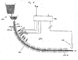
- At least one role segment in FIG. 1 if there are three, has a plurality of Anstellelemente 121 - 124 for hiring the upper and lower roller carrier 112, 114 relative to each other; see also FIG. 2 .
- the strand guide device 100 comprises a device 130 for driving the individual Anstellelemente the roller carrier so that the right and left side edge of the strand 200 are the same height.
- means 130 receives either measured elevations for the right and left side edges of the strand, or data representing an actual profile, ie, an actual cross section of the strand.
- the heights of the right and left side edge of the strand can z. B. are provided by suitable measuring devices, which, for. B. are integrated into the Anstellelemente and determine there given force or pressure conditions between the two roller carriers 112, 114 of the roller segment and infer therefrom to the heights of the right and left side edge of the strand.
- the detection of the profile of the strand can, for. B. by a suitable optical profile detection device 140; this is preferably as in FIG. 1 shown, arranged at the end of the strand guide device 100.
- the device 130 embodied as a regulating device is capable of receiving the received measurement data, be it the current heights of the lateral edges or the current actual profile of the strand, and respectively this data for the purpose of determining a system deviation with correspondingly predetermined desired variables, ie either a predetermined for the right and left side edge of the strand predetermined height H should or to compare with a desired profile.
- the control device then controls the individual Anstellelemente of the roller segment in accordance with the determined control deviation so that the control deviation becomes as zero as possible. In this way it is then ensured that any wedging previously present in the transverse direction of the strand, ie in the direction of its width, is compensated before entry of the strand into a downstream roll stand.
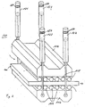
- FIG. 2 shows an elevational view of the roll segment typically used to implement the invention.
- the strand 200 in the direction of material flow is guided between the rollers 116, 118 of the roller segment.
- the roller segment in its four corner regions each having a positioning element, each of these Anstellelemente equally attacks on both roller carriers and thus causes a movement of the upper and lower roller carrier 114, 112 relative to each other.
- Anstellelemente 121 - 124 are formed as hydraulic cylinders.
- FIG. 2 indicated by reference numeral 150 measuring devices in the individual Anstellelementen, which serve to detect the above-mentioned force or pressure conditions between the roller carriers 112, 114 of the roller segment.
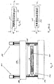
- FIG. 3 shows a cross section of the FIG. 2 known role segment, again with the same elements are designated by the same reference numerals. Especially good are in FIG. 3 to detect the significant heights Hr and HI the right and left side edge of the strand 200 for the invention. Furthermore, in FIG. 3 to recognize that the strand is not completely cured when passing through the roller segment 110, which is indicated by the still liquid part of the strand, which is denoted by the reference numeral 210. This provides for the present invention has the advantage that the applied forces to compensate for the heights Hr and HI of the right and left side edge of the strand are still relatively low, ie are less than if the strand 200 would be completely solidified.
- FIG. 4a shows an example of a detected unwanted wedging in a strand 200, that is, that in this strand 200, the heights Hr and HI of the right and left side edges are formed unequal high. According to the invention, the detection of such a situation would trigger a control to compensate for the heights on the left and right sides of the strand.
- FIG. 4b finally shows the same strand as FIG. 4a ,
- the invention done balancing the heights of the right and left side edge of the strand.
Landscapes
- Engineering & Computer Science (AREA)
- Mechanical Engineering (AREA)
- Continuous Casting (AREA)
- Moulding By Coating Moulds (AREA)
Description
- Die Erfindung betrifft ein Verfahren zum Anstellen von mindestens einem Rollensegment einer Strangführungseinrichtung einer Brammenanlage an einen Strang und eine Strangführungseinrichtung zum Durchführen dieses Verfahrens.
- Aus dem Stand der Technik sind derartige Verfahren und Vorrichtungen grundsätzlich bekannt.
- Aus der europäischen Patentanmeldung
EP 1 475 169 A1 ist ein Stützrollengerüst für Stranggießmaschinen mit Rollensegmenten bekannt. Die Rollensegmente bestehen jeweils aus einem Unterrahmen und einem Oberrahmen, welche mittels Paaren von Kolben-Zylinder-Einheiten individuell gegeneinander anstellbar sind. Den Kolben-Zylinder-Einheiten zugeordnete Sensoren, Positionsgeber, Druckgeber, Regelventilblöcke und dergleichen sind mit einer entfernt angeordneten Steuerung der Stranggießanlage verbunden. Um die Verkabelung der Sensoren zu reduzieren, wird vorgeschlagen, dass jeweils auf dem Oberrahmen entweder ein Feldbussystem oder ein Sende- und Empfangsmodul für einen bidirektionalen Datentransfer der Sensoren mit der Steuerung der Stranggießanlage vorgesehen ist. - Die japanische Druckschrift
JP 111 29003 - In der internationalen Patentanmeldung
WO 99/46071 - Der Artikel "Automatic control of strand taper and thickness during casting" von Federspiel C. et al., Millennium Steel, Mai 2001, offenbart eine Stranggießanlage mit einer Strangführung zum Führen eines in einer Kokille gegossenen Gießstrangs. Die Strangführung besteht aus einer Mehrzahl von Segmenten. Jedem Segment sind vier Anstellelemente in Form von Hydraulikzylindern zugeordnet zum Anstellen eines Oberrahmens des Segmentes in Bezug auf einen Unterrahmen des Segmentes. Jeder der Hydraulikzylinder ist individuell ansteuerbar. Es werden typischerweise für die Hydraulikzylinder Soll-Positionswerte vorgegeben, welche während des Gießbetriebs - bis auf vorgegebene Toleranzen - eingehalten werden müssen. Die Hydraulikzylinder auf den Segmenten dienen primär dazu, den sogenannten "Taper" des Gießstrangs, d. h. seine Dickenreduktion in Gießrichtung in gewünschter Weise einzustellen.
- Die europäische Patentanmeldung
EP 1 504 832 A1 offenbart ein Verfahren und eine Einrichtung zum berührungslosen Messen der Profildicke und/oder der Profilform an Gießsträngen einer Mehrstrariggießanlage für flüssige Metalle, insbesondere für Stahl. In dieser Druckschrift wird es als bekannt beschrieben, dass Profildicken-Messungen an Stranggießanlagen auf Grundlage von Laser- oder Isotopen-Strahlungssystemen erfolgen. Weiterhin wird auf eine bekannte Einrichtung zur Bestimmung der Spießkantigkeit von Stranggieß-Knüppeln verwiesen. - Ausgehend von diesem Stand der Technik liegt der Erfindung die Aufgabe zugrunde, ein bekanntes Verfahren zum Anstellen eines Rollensegmentes in einer Strangführungseinrichtung an einen Strang und eine entsprechende Strangführungseinrichtung dahingehend weiterzubilden, dass der Strangführungseinrichtung nachgeschaltete Walzgerüste im Hinblick auf die an sie gestellten Aufgaben und im Hinblick auf ihre mechanische Belastung während ihres Betriebs entlastet werden und dass die Qualität des Strangs verbessert wird.
- Diese Aufgabe wird durch das im Patentanspruch 1 beanspruchte Verfahren gelöst.
- Traditionell war es die Aufgabe der der Strangführungseinrichtung nachgeschalteteten Walzgerüste, eine eventuell in einem zugeführten Strang vorhandene unerwünschte Keiligkeit im Profil des Strangs, d. h. ungleich hohe Seitenränder des Strangs auszugleichen. Dies führte jedoch zu einer unerwünschten ungleichmäßigen mechanischen Belastung der Walzen im Walzgerüst über ihre jeweilige Walzenbreite und damit zu einer unerwünschten ungleichmäßigen Abnutzung der Walzen. Durch die Erfindung wird in vorteilhafter Weise sichergestellt, dass eine eventuell vorhandene Keiligkeit des Profils des gegossenen Strangs, bereits in der Strangführungseinrichtung, d. h. also noch vor Eintritt in die nachgeschalteten Walzgerüste ausgeglichen wird. Idealerweise wird somit durch die vorliegende Erfindung sichergestellt, dass den Walzgerüsten nur ein Strang ohne Keiligkeit zugeführt wird. Die Walzgerüste werden auf diese Weise sowohl mechanisch wie auch im Hinblick auf die von Ihnen früher zu erfüllende Aufgabe der Behebung einer eventuellen Keiligkeit des Strangs entlastet; außerdem wird die Qualität des Strangs so letztendlich verbessert.
- Bei der beanspruchten Regelung wird das Ist-Profil des Strangs inklusive der Höhen der rechten und linken Seitenkante erfasst und zur Bestimmung einer entsprechenden Regelabweichung mit einem Soll-Profil enthaltend eine vorgegebene gleiche Sollhöhe (HSoll) für die rechte und linke Seitenkante verglichen. Die einzelnen Anstellelemente des Rollensegmentes werden dann nach Maßgabe der Regelabweichung individuell so angesteuert, dass die Höhen der rechten und linken Seitenkante des Strangs jeweils auf die vorgegebene gleiche Sollhöhe gewalzt werden.
- Bei der Regelung der Höhen auf der rechten und linken Seitenkante des Strangs ist eine Profilregelung für das Profil, d. h. den Querschnitt des Strangs vorzusehen. Dazu wird zunächst das Ist-Profil des Strangs erfasst und mit einem vorgegebenen Soll-Profil zwecks Bestimmung einer Profil-Regelabweichung verglichen. Dann erfolgt das Anstellen der einzelnen Anstellelemente des Rollensegmentes nach Maßgabe der zuvor ermittelten Profil-Regelabweichung zwecks Angleichung des Ist-Profils an das vorgegebene Soll-Profil. Auch diese Profil-Angleichung schließt allerdings einen im Rahmen der vorliegenden Erfindung zwingend notwendigen Ausgleich der Höhen der rechten und linken Seitenkante des Strangs mit ein.
- Die Messwerteerfassung des Ist-Profils erfolgt am Ausgang des letzten Rollensegmentes der Strangführungseinrichtung, d. h. kurz vor Eintritt in das Walzgerüst. Weil mit der erfindungsgemäßen Regelung eine Reduzierung der oben erwähnten Regelabweichungen auf Null angestrebt wird, wird auf diese Weise sichergestellt, dass auch tatsächlich nur ein Strang mit gleich hohen Seitenkanten dem nachgeschalteten Walzgerüst zugeführt wird.
- Die Behebung der eventuellen Keiligkeit in der Strangführungseinrichtung erfolgt an einer Position bzw. an Rollensegmenten, bei denen der Strang noch nicht durcherstarrt ist. Dies hat den Vorteil, dass dann zur Behebung der Keiligkeit wesentlich geringere Kräfte von den Rollen der Rollensegmente auf den Strang ausgeübt werden müssen, als wenn der Strang bereits durcherstarrt wäre, wie dies in der Regel bei Eintritt in die nachgeschalteten Walzgerüste der Fall ist.
- Vorteilhafterweise kann das individuelle Anstellen der Anstellelemente zwecks Behebung der Keiligkeit bei mehreren Rollensegmenten der Strangführungseinrichtung erfolgen.
- Eine Anstellung der Anstellelemente bei mehreren Rollensegmenten erfordert zwar einen technisch größeren Aufwand, hat jedoch den Vorteil, dass dann bei den einzelnen Anstellelementen lediglich geringere Kräfte aufgewandt werden müssen; dies gilt insbesondere deswegen, weil dann eine Vielzahl von Anstellelementen bei mehreren Rollensegmenten bereitstehen, um die Keiligkeit insgesamt auszugleichen.
- Vorteilhafte Ausgestaltungen der Strangführungseinrichtung und insbesondere der Anstellelemente sind Gegenstand der Unteransprüche.
- Der Beschreibung sind insgesamt vier Figuren beigefügt, wobei
- Figur 1
- eine neue Strangführungseinrichtung gemäß der Erfindung;
- Figur 2
- eine Aufrissansicht eines Rollensegmentes;
- Figur 3
- einen Querschnitt durch das Rollensegment;
- Figur 4a
- einen Strang mit Keiligkeit in dem Rollensegment;
- Figur 4b
- einen Strang ohne Keiligkeit zwischen zwei konischen Rollen eines Rollen-segmentes
- Die Erfindung wird nachfolgend in Form von Ausführungsbeispielen unter Bezugnahme auf die genannten Figuren detailliert beschrieben.
-
Figur 1 zeigt die erfindungsgemäße Strangführungseinrichtung zum Führen eines Strangs 200 nach Verlassen einer Gießeinrichtung 300. Die Strangführungseinrichtung umfasst eine Mehrzahl von Rollensegmenten 110 -n mit n = 1- N, wobei jedes Rollensegment 110 -n jeweils einen oberen und einen unteren Rollenträger 112, 114 aufweist. Jeder Rollenträger dient zum Tragen von mindestens einer Rolle zum Führen des Strangs nach Verlassen der Gießeinrichtung zwischen den Rollen. Zumindest ein Rollensegment, inFigur 1 sind es drei, weist mehrere Anstellelemente 121 - 124 auf zum Anstellen des oberen und unteren Rollenträgers 112, 114 relativ zueinander; siehe auchFigur 2 . Weiterhin umfasst die Strangführungseinrichtung 100 eine Einrichtung 130 zum Ansteuern der einzelnen Anstellelemente der Rollenträger so, dass die rechte und linke Seitenkante des Strangs 200 gleich hoch werden. - Als Regelungseinrichtung empfängt die Einrichtung 130 entweder gemessene Höhen für die rechte und linke Seitenkante des Strangs oder Daten, welche ein Ist-Profil, d. h. einen Ist-Querschnitt des Strangs repräsentieren. Die Höhen der rechten und linken Seitenkante des Strangs können z. B. von geeigneten Messeinrichtungen bereitgestellt werden, welche z. B. in die Anstellelemente integriert sind und dort gegebene Kraft- oder Druckverhältnisse zwischen den beiden Rollenträgern 112, 114 des Rollensegmentes ermitteln und daraus auf die Höhen der rechten und linken Seitenkante des Strangs rückschließen. Die Erfassung des Profils des Strangs kann z. B. durch eine geeignete optische Profilerfassungseinrichtung 140 erfolgen; diese ist vorzugsweise, wie in
Figur 1 dargestellt, am Ende der Strangführungseinrichtung 100 angeordnet. Die als Regelungseinrichtung ausgebildete Einrichtung 130 ist in der Lage, die empfangenen Messdaten, sei es die aktuellen Höhen der Seitenkanten oder das aktuelle Ist-Profil des Strangs, zu empfangen und diese Daten jeweils zwecks Ermittlung einer Regelabweichung mit entsprechend vorgegebenen Soll-Größen, d. h. entweder einer einheitlich für die rechte und linke Seitenkante des Strangs vorgegebenen Sollhöhe Hsoll oder mit einem Soll-Profil, zu vergleichen. Die Regelungseinrichtung steuert dann die einzelnen Anstellelemente des Rollensegmentes nach Maßgabe der ermittelten Regelabweichung so an, dass die Regelabweichung möglichst zu Null wird. Auf diese Weise wird dann gewährleistet, dass eine eventuell zuvor in Querrichtung des Strangs, d. h. in Richtung seiner Breite vorhandene Keiligkeit vor Eintritt des Strangs in ein nachgeschaltetes Walzgerüst ausgeglichen ist. -
Figur 2 zeigt eine Aufrissansicht des typischerweise zur Realisierung der Erfindung verwendeten Rollensegmentes. InFigur 2 sind gleiche Elemente wie inFigur 1 mit gleichen Bezugszeichen bezeichnet. Es ist gut zu erkennen, dass der Strang 200 in Materialflussrichtung, angedeutet durch einen horizontalen Pfeil, zwischen den Rollen 116, 118 des Rollensegmentes hindurch geführt wird. Weiterhin ist zu erkennen, dass bei dem hier gezeigten Beispiel das Rollensegment in seinen vier Eckbereichen jeweils ein Anstellelement aufweist, wobei jedes dieser Anstellelemente gleichermaßen an beiden Rollenträgern angreift und so eine Bewegung des oberen und des unteren Rollenträgers 114, 112 relativ zueinander bewirkt. Die inFigur 2 gezeigten Anstellelemente 121 - 124 sind als Hydraulikzylinder ausgebildet. Weiterhin sind inFigur 2 mit dem Bezugszeichen 150 Messeinrichtungen in den einzelnen Anstellelementen angedeutet, welche zum Erfassen der o. g. Kraft- oder Druckverhältnisse zwischen den Rollenträgern 112, 114 des Rollensegmentes dienen. -
Figur 3 zeigt einen Querschnitt des ausFigur 2 bekannten Rollensegmentes, wobei wiederum gleiche Elemente mit gleichen Bezugszeichen bezeichnet sind. Besonders gut sind inFigur 3 die für die Erfindung wesentlichen Höhen Hr und HI der rechten und linken Seitenkante des Strangs 200 zu erkennen. Weiterhin ist inFigur 3 zu erkennen, dass der Strang beim Durchlaufen des Rollensegmentes 110 noch nicht vollständig ausgehärtet ist, was durch den noch flüssigen Teil des Strangs, der durch das Bezugszeichen 210 bezeichnet ist, angedeutet ist. Dies bietet für die vorliegende Erfindung den Vorteil, dass die aufzubringenden Kräfte zum Ausgleich der Höhen Hr und HI der rechten und linken Seitenkante des Strangs noch relativ gering sind, d. h. geringer sind, als wenn der Strang 200 vollständig durcherstarrt wäre. -
Figur 4a zeigt ein Beispiel für eine erfasste unerwünschte Keiligkeit bei einem Strang 200, d. h. dass bei diesem Strang 200 die Höhen Hr und HI der rechten und linken Seitenkante ungleich hoch ausgebildet sind. Erfindungsgemäß würde die Erfassung einer solchen Situation eine Regelung zum Ausgleich der Höhen auf der linken und rechten Seite des Strangs auslösen. -
Figur 4b zeigt schließlich denselben Strang wieFigur 4a , allerdings nach erfindungsgemäß erfolgtem Ausgleich der Höhen der rechten und linken Seitenkante des Strangs. Eine eventuell vorhandene unsymmetrische Abnutzung der Rollen 116, 118 des Rollensegmentes, die zu einer konischen Ausbildung geführt hat, ist für die Durchführung der vorliegenden Erfindung unerheblich, weil sie durch die beanspruchte individuelle Ansteuerung der Anstellelemente 121 - 124 auf der linken und rechten Seite des Strangs in Materialflussrichtung gesehen ausgeglichen wird.
Claims (7)
- Verfahren zum Anstellen von mindestens einem Rollensegment (110) einer Strangführungseinrichtung (100) einer Brammenanlage an einen Strang, wobei das Rollensegment einen oberen und einen unteren Rollenträger (114, 112) aufweist, die jeweils mindestens eine Rolle (116, 118) tragen zum Führen des Strangs (200) zwischen den Rollen, und wobei der - in Materialflussrichtung gesehen - rechten und linken Seite des Rollensegmentes (110) jeweils mindestens ein Anstellelement (121-124) zum Anstellen der beiden Rollenträger (114, 112) relativ zueinander zugeordnet ist, umfassend folgenden Schritt:Individuelles Ansteuern der einzelnen Anstellelemente (121-124),wobei das Ist-Profil des Strangs inklusive der Höhen (Hr, HI) der rechten und linken Seitenkante des Strangs (200) erfasst und mit einem Soll-Profil enthaltend eine vorgegebene gleiche Sollhöhe (Hsoll) für die rechte und linke Seitenkante verglichen wird; und die einzelnen Anstellelemente (121-124) des Rollensegmentes (116) nach Maßgabe der aus dem Vergleich resultierenden Regelabweichung individuell so angesteuert werden, dass das Ist-Profil an das Soll-Profil angepasst wird, inklusive eines Ausgleichs der Höhen der rechten und linken Seitenkante des Strangs (200),dadurch gekennzeichnet,dass das Anstellen in einem Bereich des Strangs (200) erfolgt, der beim Durchlaufen des Rollensegmentes (110) noch nicht durcherstarrt ist, und dass die Höhen (Hr, HI) der Seitenkanten des Strangs oder dessen Ist-Profil am Ausgang des mindestens einen Rollensegmentes der Strangführungseinrichtung (100), zumindest am Ausgang des letzten Rollensegmentes (100-N) der Strangführung, erfasst werden oder wird.
- Verfahren nach Anspruch 1,
dadurch gekennzeichnet,
dass das individuelle Anstellen der Anstellelemente (121-124) bei einem einzelnen oder mehreren Rollensegmenten (110) der Strangführungseinrichtung (100) erfolgt. - Strangführungseinrichtung (100) zum Führen eines Strangs (200) nach Verlassen einer Gießeinrichtung (300), umfassend:mindestens ein Rollensegment (100-n) mit einem oberen und einem unteren Rollenträger (112, 114), wobei die Rollenträger jeweils mindestens eine Rolle (116, 118) aufweisen zum Führen des Strangs (200) nach Verlassen der Gießeinrichtung zwischen den Rollen;mindestens jeweils ein Anstellelement (121-124) auf der - in Materiälflussrichtung gesehen - rechten und linken Seite des Rollensegments (110) zum Anstellen des oberen und unteren Rollenträgers (112, 114) relativ zueinander; undeine Regelungseinrichtung (130) zum Ansteuern der Anstellelemente (121-124);wobei eine Profilerfassungseinrichtung (140) vorgesehen ist, zum Erfassen des Querschnitts des Strangs (200) innerhalb der Strangführungseinrichtung als Ist-Profil inklusive eines eventuellen Unterschieds zwischen den Höhen (Hr, HI) der rechten und linken Seitenkante des Strangs; unddie Regefungseinrichtung (130) ausgebildet ist, die Anstellelemente (121-124) der Rollenträger so anzusteuern, dass das Ist-Profil an ein vorgegebenes Soll-Profil mit gleichen Höhen (Hr, HI) auf der rechten und linken Seitenkante des Strangs (200) angepasst ist,dadurch gekennzeichnet, dassdie Profilerfassungseinrichtung (140) zumindest am Ausgang des letzten Rollensegmentes der Strangführungseinrichtung angeordnet ist; unddas Anstellen in einem Bereich des Strangs erfolgt, der beim Durchlaufen des Rollensegmentes noch nicht durcherstarrt ist.
- Strangführungseinrichtung (100) nach Anspruch 3, dadurch gekennzeichnet, dass die Einrichtung (130) als Steuerungs- oder Regeleinrichtung ausgebildet ist, um die einzelnen Anstellelemente (121-124) der Rollenträger so anzusteuern, dass die rechte und linke Seitenkante des Strangs (200) auf die gleiche vorgegebene Sollhöhe (Hsoll) gewalzt werden.
- Strangführungseinrichtung (100) nach Anspruch 3 oder 4, dadurch gekennzeichnet, dass das Rollensegment (110) in seinen vier Eckbereichen jeweils ein Anstellelement (121-124) aufweist.
- Strangführungseinrichtung (100) nach einem der Ansprüche 3 bis 5, dadurch gekennzeichnet, dass die Anstellelemente (121-124) jeweils als Hydraulikzylinder ausgebildet sind.
- Strangführungselement (100) nach einem der Ansprüche 3 bis 6, gekennzeichnet durch eine Messeinrichtung (150), welche in die Anstellelemente (121-124) integriert ist, zum Erfassen von Kraft- oder Druckverhältnissen zwischen den beiden Rollenträgern (112, 114) des Rollensegmentes.
Applications Claiming Priority (2)
| Application Number | Priority Date | Filing Date | Title |
|---|---|---|---|
| DE102005055530A DE102005055530A1 (de) | 2005-11-22 | 2005-11-22 | Verfahren und Vorrichtung zum Anstellen von mindestens einem Rollensegment einer Strangführungseinrichtung an einen Strang |
| PCT/EP2006/010063 WO2007059827A1 (de) | 2005-11-22 | 2006-10-19 | Verfahren und vorrichtung zum anstellen von mindestens einem rollensegment einer strangführungseinrichtung an einen strang |
Publications (3)
| Publication Number | Publication Date |
|---|---|
| EP1917115A1 EP1917115A1 (de) | 2008-05-07 |
| EP1917115B1 EP1917115B1 (de) | 2009-06-03 |
| EP1917115B2 true EP1917115B2 (de) | 2018-03-14 |
Family
ID=37685649
Family Applications (1)
| Application Number | Title | Priority Date | Filing Date |
|---|---|---|---|
| EP06828830.7A Active EP1917115B2 (de) | 2005-11-22 | 2006-10-19 | Verfahren und vorrichtung zum anstellen von mindestens einem rollensegment einer strangführungseinrichtung an einen strang |
Country Status (11)
| Country | Link |
|---|---|
| US (3) | US8205661B2 (de) |
| EP (1) | EP1917115B2 (de) |
| JP (1) | JP5111391B2 (de) |
| KR (1) | KR20080072729A (de) |
| CN (1) | CN101374617B (de) |
| AT (1) | ATE432783T1 (de) |
| CA (1) | CA2630856A1 (de) |
| DE (2) | DE102005055530A1 (de) |
| RU (1) | RU2379156C1 (de) |
| UA (1) | UA88241C2 (de) |
| WO (1) | WO2007059827A1 (de) |
Families Citing this family (4)
| Publication number | Priority date | Publication date | Assignee | Title |
|---|---|---|---|---|
| DE102005055530A1 (de) * | 2005-11-22 | 2007-05-24 | Sms Demag Ag | Verfahren und Vorrichtung zum Anstellen von mindestens einem Rollensegment einer Strangführungseinrichtung an einen Strang |
| CA2706284C (en) * | 2008-01-14 | 2015-08-25 | Sms Concast Ag | Continuous casting system particularly for long steel products, and a method for continuous casting |
| CN107116195B (zh) * | 2017-05-31 | 2019-01-15 | 西安交通大学 | 一种基于流数据的动态轻压下控制方法 |
| CN110181018B (zh) * | 2018-05-17 | 2022-01-14 | 江阴兴澄特种钢铁有限公司 | 一种连铸坯厚度在线测量及压下量调整系统 |
Citations (7)
| Publication number | Priority date | Publication date | Assignee | Title |
|---|---|---|---|---|
| EP1043095A1 (de) † | 1999-04-10 | 2000-10-11 | Sms Schloemann-Siemag Aktiengesellschaft | Verfahren und Vorrichtung zum Einstellen des Brammenprofils einer stranggegossenen Bramme, insbesondere einer Dünnbramme |
| WO2002098587A2 (de) † | 2001-06-01 | 2002-12-12 | Sms Demag Aktiengesellschaft | Verfahren zum einstellen der dynamischen soft reduction an stranggiessmaschinen |
| EP1504832A1 (de) † | 2003-08-08 | 2005-02-09 | SMS Demag Aktiengesellschaft | Verfahren und Einrichtung zum berührungslosen Messen der Profildicke und/oder der Profilform an Giesssträngen einer Mehrstranggiessanlage für flüssige Metalle, insbesondere für Stahl |
| WO2006042606A1 (de) † | 2004-10-13 | 2006-04-27 | Siemens Vai Metals Technologies Gmbh & Co | Verfahren und vorrichtung zum kontinuierlichen herstellen eines dünnen metallbandes |
| WO2007068338A1 (de) † | 2005-12-14 | 2007-06-21 | Sms Demag Ag | Verfahren zum stranggiessen dünner metallbänder und stranggiessanlage |
| WO2008033880A1 (en) † | 2006-09-15 | 2008-03-20 | Honeywell International Inc. | A sealed cavity method and apparatus for use in sensor modules |
| EP1188493B2 (de) † | 2000-09-13 | 2009-05-20 | SMS Demag AG | Regelverfahren zum Walzen eines Bandes in einem Walzgerüst |
Family Cites Families (13)
| Publication number | Priority date | Publication date | Assignee | Title |
|---|---|---|---|---|
| DE4138740A1 (de) * | 1991-11-26 | 1993-05-27 | Schloemann Siemag Ag | Verfahren und vorrichtung zum stranggiessen von brammen oder bloecken |
| JP3019720B2 (ja) * | 1994-06-16 | 2000-03-13 | 日本鋼管株式会社 | キャンバ矯正機能を有する圧延機 |
| DE19511113A1 (de) | 1995-03-25 | 1996-09-26 | Schloemann Siemag Ag | Strangführung einer Stranggießanlage für Dünnbrammen |
| US6102101A (en) * | 1995-10-18 | 2000-08-15 | Sumitomo Metal Industries, Ltd. | Continuous casting method and apparatus thereof |
| JPH11129003A (ja) * | 1997-10-30 | 1999-05-18 | Aisin Seiki Co Ltd | 傾斜圧延機及び傾斜圧延方法 |
| DE19809807C2 (de) * | 1998-03-09 | 2003-03-27 | Sms Demag Ag | Anstellverfahren für ein Rollensegment einer Stranggießanlage |
| DE19824366A1 (de) * | 1998-05-30 | 1999-12-02 | Schloemann Siemag Ag | Strangführungssegment für Brammengießanlagen |
| DE19836843A1 (de) * | 1998-08-14 | 2000-02-17 | Schloemann Siemag Ag | Vorrichtung zum hydraulischen Anstellen der Rollen von Strangführungssegmenten einer Stranggießanlage |
| US6837301B2 (en) * | 1999-02-05 | 2005-01-04 | Castrip Llc | Strip casting apparatus |
| AUPQ818000A0 (en) * | 2000-06-15 | 2000-07-06 | Bhp Steel (Jla) Pty Limited | Strip casting |
| DE10042079A1 (de) * | 2000-08-26 | 2002-04-25 | Sms Demag Ag | Stranggießanlage mit Soft-Reduction-Strecke |
| DE10319863B4 (de) * | 2003-05-03 | 2021-07-01 | Sms Group Gmbh | Stützrollengerüst für Knüppel-, Vorblock-, Block-, Vorprofil-, Dünn- und Brammen-Stranggießmaschinen, zum Gießen von flüssigen Metallen, insbesondere von flüssigen Stahlwerkstoffen |
| DE102005055530A1 (de) * | 2005-11-22 | 2007-05-24 | Sms Demag Ag | Verfahren und Vorrichtung zum Anstellen von mindestens einem Rollensegment einer Strangführungseinrichtung an einen Strang |
-
2005
- 2005-11-22 DE DE102005055530A patent/DE102005055530A1/de not_active Withdrawn
-
2006
- 2006-10-19 KR KR1020087014980A patent/KR20080072729A/ko not_active Ceased
- 2006-10-19 WO PCT/EP2006/010063 patent/WO2007059827A1/de not_active Ceased
- 2006-10-19 JP JP2008541603A patent/JP5111391B2/ja not_active Expired - Fee Related
- 2006-10-19 CN CN2006800378926A patent/CN101374617B/zh not_active Expired - Fee Related
- 2006-10-19 DE DE502006003898T patent/DE502006003898D1/de active Active
- 2006-10-19 AT AT06828830T patent/ATE432783T1/de active
- 2006-10-19 UA UAA200808341A patent/UA88241C2/ru unknown
- 2006-10-19 CA CA002630856A patent/CA2630856A1/en not_active Abandoned
- 2006-10-19 EP EP06828830.7A patent/EP1917115B2/de active Active
- 2006-10-19 RU RU2008125113/02A patent/RU2379156C1/ru active
- 2006-10-19 US US12/085,416 patent/US8205661B2/en active Active
-
2011
- 2011-05-13 US US13/107,771 patent/US20110214835A1/en not_active Abandoned
- 2011-05-13 US US13/107,776 patent/US8820392B2/en active Active
Patent Citations (7)
| Publication number | Priority date | Publication date | Assignee | Title |
|---|---|---|---|---|
| EP1043095A1 (de) † | 1999-04-10 | 2000-10-11 | Sms Schloemann-Siemag Aktiengesellschaft | Verfahren und Vorrichtung zum Einstellen des Brammenprofils einer stranggegossenen Bramme, insbesondere einer Dünnbramme |
| EP1188493B2 (de) † | 2000-09-13 | 2009-05-20 | SMS Demag AG | Regelverfahren zum Walzen eines Bandes in einem Walzgerüst |
| WO2002098587A2 (de) † | 2001-06-01 | 2002-12-12 | Sms Demag Aktiengesellschaft | Verfahren zum einstellen der dynamischen soft reduction an stranggiessmaschinen |
| EP1504832A1 (de) † | 2003-08-08 | 2005-02-09 | SMS Demag Aktiengesellschaft | Verfahren und Einrichtung zum berührungslosen Messen der Profildicke und/oder der Profilform an Giesssträngen einer Mehrstranggiessanlage für flüssige Metalle, insbesondere für Stahl |
| WO2006042606A1 (de) † | 2004-10-13 | 2006-04-27 | Siemens Vai Metals Technologies Gmbh & Co | Verfahren und vorrichtung zum kontinuierlichen herstellen eines dünnen metallbandes |
| WO2007068338A1 (de) † | 2005-12-14 | 2007-06-21 | Sms Demag Ag | Verfahren zum stranggiessen dünner metallbänder und stranggiessanlage |
| WO2008033880A1 (en) † | 2006-09-15 | 2008-03-20 | Honeywell International Inc. | A sealed cavity method and apparatus for use in sensor modules |
Non-Patent Citations (8)
| Title |
|---|
| "Optimization of Slab Centerline Quality Using Dynamic Soft Reduction", AIST Konferenz 2007, Seite 4 zu "Thermal Tapering" und "DSR" † |
| CAPPEL J. ET AL: "Centre segregation, soft reduction and oxide cleanness for large diameter line pipe with highest demands on HIC", STEEL RESEARCH INTERNATIONAL, vol. 76, no. 8, 2005, pages 589 † |
| Fachpublikation Stranggiesstechnik, SMS Demag AG, 1999: "Dynamische Strangführung durch hydraulisch geregelte Segmente", Seiten 2-5 † |
| FEDERSPIEL C. ET AL: "ASTC - VAI's automatic strand taper/tickness control system", AUTOMATION & PROCESS CONTROL SESSION, vol. 53, June 2000 (2000-06-01), pages 1 - 8 † |
| FEDERSPIEL C. ET AL: "Automatic control of strand taper und thickness during casting", MILLENIUM STEEL, May 2001 (2001-05-01), pages 232 - 238, XP002517077 † |
| GAMMAL T.E. ET AL: "Materialsammlung zum Praktikum Metallurgie", vol. 2. AUFL., 1992, INSTITUT FÜR EISENHÜTTENKUNDE DER RWTH, AACHEN, pages: 354 - 359 † |
| MURRENHOF H.: "Grundlage der Fluidtechnik: Hydraulik", vol. 1. AUFL., part TEIL 1 1997, RWTH, AACHEN, pages: 148-149 - 308-313 † |
| SCHWERDTFEGER K.: "Metallurgie des Stranggießens", 1992, VERLAG STAHLEISEN GMBH, DÜSSELDORF, pages: 330 † |
Also Published As
| Publication number | Publication date |
|---|---|
| DE102005055530A1 (de) | 2007-05-24 |
| WO2007059827A1 (de) | 2007-05-31 |
| ATE432783T1 (de) | 2009-06-15 |
| JP5111391B2 (ja) | 2013-01-09 |
| DE502006003898D1 (de) | 2009-07-16 |
| US20090159232A1 (en) | 2009-06-25 |
| KR20080072729A (ko) | 2008-08-06 |
| CA2630856A1 (en) | 2007-05-31 |
| JP2009516591A (ja) | 2009-04-23 |
| EP1917115B1 (de) | 2009-06-03 |
| CN101374617A (zh) | 2009-02-25 |
| US20110214835A1 (en) | 2011-09-08 |
| US20110220315A1 (en) | 2011-09-15 |
| US8205661B2 (en) | 2012-06-26 |
| CN101374617B (zh) | 2013-07-17 |
| US8820392B2 (en) | 2014-09-02 |
| RU2379156C1 (ru) | 2010-01-20 |
| UA88241C2 (ru) | 2009-09-25 |
| EP1917115A1 (de) | 2008-05-07 |
Similar Documents
| Publication | Publication Date | Title |
|---|---|---|
| EP2825332B1 (de) | Vorrichtung und verfahren zum richten von metallband | |
| DE3413269C2 (de) | ||
| DE19809807C2 (de) | Anstellverfahren für ein Rollensegment einer Stranggießanlage | |
| EP0545104A2 (de) | Verfahren und Vorrichtung zum Stranggiessen von Brammen oder Blöcken | |
| DE2133144A1 (de) | Verfahren und vorrichtung zum ausfoerdern und richten eines stranges in einer stranggiessanlage | |
| DE69404527T2 (de) | Walzwerk und Verfahren | |
| DE102009010251A1 (de) | Vorrichtung und Verfahren zur Sekundärkühlung in einer Stranggießanlage | |
| EP0275875A2 (de) | Anstellvorrichtung für ein Universalwalzgerüst | |
| EP0834364A2 (de) | Verfahren und Vorrichtung für Hochgeschwindigkeits-Stranggiessanlagen mit einer Strangdickenreduktion während der Erstarrung | |
| EP2790846B1 (de) | Verfahren zur bearbeitung von walzgut in einem warmwalzwerk | |
| WO2011134811A2 (de) | Minimierung des bandzugs eines walzgutes zwischen zwei walzeinheiten | |
| DE3240602C2 (de) | ||
| AT390900B (de) | Anordnung zum regeln der stellungen der arbeitswalzen in einem quartowalzwerk zum walzen von metall | |
| DE10160636B4 (de) | Verfahren zum Einstellen eines Gießspaltes an einer Strangführung einer Stranggießanlage und Stranggießanlage zur Durchführung des Verfahrens | |
| EP1917115B2 (de) | Verfahren und vorrichtung zum anstellen von mindestens einem rollensegment einer strangführungseinrichtung an einen strang | |
| EP1112129B1 (de) | Verfahren zur erzeugung bestimmter produkteigenschaften beim walzen von stahlqualitäten im austenitischen, gemischt austenitisch-ferritischen und ferritischen bereich | |
| WO2018108652A1 (de) | Verfahren und vorrichtung zum regeln einer stranggiessanlage | |
| EP3325186B1 (de) | Anlage und verfahren zum beseitigen von planheitsfehlern eines metallischen flachprodukts | |
| EP2268427B1 (de) | Betriebsverfahren für eine kaltwalzstrasse mit verbesserter dynamik | |
| AT399175B (de) | Kalander zur oberflächenbearbeitung von materialbahnen | |
| EP0995506A2 (de) | Zugregelverfahren für einen Walzgutabschnitt | |
| EP4240544B1 (de) | Stabilisierung des walzprodukts während des auf- und/oder zufahrens eines walzgerüsts | |
| DE102008015008B4 (de) | Verfahren zum Betreiben einer Strangführungseinrichtung | |
| DE3401894A1 (de) | Verfahren zum herstellen von walzband mit hoher bandprofil- und bandplanheitsguete | |
| EP1543900B1 (de) | Verfahren und Stranggiessmaschine zum Grundeinstellen und Kontrollieren der Rollenspalte von Stützrollensegmenten oder Treiberrollenpaaren beim Giessen von flüssigen Metallen, insbesondere von flüssigen Stahlwerkstoffen |
Legal Events
| Date | Code | Title | Description |
|---|---|---|---|
| PUAI | Public reference made under article 153(3) epc to a published international application that has entered the european phase |
Free format text: ORIGINAL CODE: 0009012 |
|
| 17P | Request for examination filed |
Effective date: 20080307 |
|
| AK | Designated contracting states |
Kind code of ref document: A1 Designated state(s): AT BE BG CH CY CZ DE DK EE ES FI FR GB GR HU IE IS IT LI LT LU LV MC NL PL PT RO SE SI SK TR |
|
| 17Q | First examination report despatched |
Effective date: 20080625 |
|
| GRAP | Despatch of communication of intention to grant a patent |
Free format text: ORIGINAL CODE: EPIDOSNIGR1 |
|
| GRAS | Grant fee paid |
Free format text: ORIGINAL CODE: EPIDOSNIGR3 |
|
| GRAA | (expected) grant |
Free format text: ORIGINAL CODE: 0009210 |
|
| AK | Designated contracting states |
Kind code of ref document: B1 Designated state(s): AT BE BG CH CY CZ DE DK EE ES FI FR GB GR HU IE IS IT LI LT LU LV MC NL PL PT RO SE SI SK TR |
|
| REG | Reference to a national code |
Ref country code: GB Ref legal event code: FG4D Free format text: NOT ENGLISH |
|
| REG | Reference to a national code |
Ref country code: CH Ref legal event code: EP |
|
| RAP2 | Party data changed (patent owner data changed or rights of a patent transferred) |
Owner name: SMS SIEMAG AG |
|
| REG | Reference to a national code |
Ref country code: IE Ref legal event code: FG4D Free format text: LANGUAGE OF EP DOCUMENT: GERMAN |
|
| REF | Corresponds to: |
Ref document number: 502006003898 Country of ref document: DE Date of ref document: 20090716 Kind code of ref document: P |
|
| NLT2 | Nl: modifications (of names), taken from the european patent patent bulletin |
Owner name: SMS SIEMAG AG Effective date: 20090617 |
|
| PG25 | Lapsed in a contracting state [announced via postgrant information from national office to epo] |
Ref country code: LT Free format text: LAPSE BECAUSE OF FAILURE TO SUBMIT A TRANSLATION OF THE DESCRIPTION OR TO PAY THE FEE WITHIN THE PRESCRIBED TIME-LIMIT Effective date: 20090603 Ref country code: FI Free format text: LAPSE BECAUSE OF FAILURE TO SUBMIT A TRANSLATION OF THE DESCRIPTION OR TO PAY THE FEE WITHIN THE PRESCRIBED TIME-LIMIT Effective date: 20090603 |
|
| NLV1 | Nl: lapsed or annulled due to failure to fulfill the requirements of art. 29p and 29m of the patents act | ||
| PG25 | Lapsed in a contracting state [announced via postgrant information from national office to epo] |
Ref country code: SE Free format text: LAPSE BECAUSE OF FAILURE TO SUBMIT A TRANSLATION OF THE DESCRIPTION OR TO PAY THE FEE WITHIN THE PRESCRIBED TIME-LIMIT Effective date: 20090903 Ref country code: NL Free format text: LAPSE BECAUSE OF FAILURE TO SUBMIT A TRANSLATION OF THE DESCRIPTION OR TO PAY THE FEE WITHIN THE PRESCRIBED TIME-LIMIT Effective date: 20090603 Ref country code: SI Free format text: LAPSE BECAUSE OF FAILURE TO SUBMIT A TRANSLATION OF THE DESCRIPTION OR TO PAY THE FEE WITHIN THE PRESCRIBED TIME-LIMIT Effective date: 20090603 Ref country code: PL Free format text: LAPSE BECAUSE OF FAILURE TO SUBMIT A TRANSLATION OF THE DESCRIPTION OR TO PAY THE FEE WITHIN THE PRESCRIBED TIME-LIMIT Effective date: 20090603 Ref country code: LV Free format text: LAPSE BECAUSE OF FAILURE TO SUBMIT A TRANSLATION OF THE DESCRIPTION OR TO PAY THE FEE WITHIN THE PRESCRIBED TIME-LIMIT Effective date: 20090603 |
|
| REG | Reference to a national code |
Ref country code: IE Ref legal event code: FD4D |
|
| PG25 | Lapsed in a contracting state [announced via postgrant information from national office to epo] |
Ref country code: IE Free format text: LAPSE BECAUSE OF FAILURE TO SUBMIT A TRANSLATION OF THE DESCRIPTION OR TO PAY THE FEE WITHIN THE PRESCRIBED TIME-LIMIT Effective date: 20090603 Ref country code: ES Free format text: LAPSE BECAUSE OF FAILURE TO SUBMIT A TRANSLATION OF THE DESCRIPTION OR TO PAY THE FEE WITHIN THE PRESCRIBED TIME-LIMIT Effective date: 20090914 Ref country code: CZ Free format text: LAPSE BECAUSE OF FAILURE TO SUBMIT A TRANSLATION OF THE DESCRIPTION OR TO PAY THE FEE WITHIN THE PRESCRIBED TIME-LIMIT Effective date: 20090603 Ref country code: EE Free format text: LAPSE BECAUSE OF FAILURE TO SUBMIT A TRANSLATION OF THE DESCRIPTION OR TO PAY THE FEE WITHIN THE PRESCRIBED TIME-LIMIT Effective date: 20090603 Ref country code: RO Free format text: LAPSE BECAUSE OF FAILURE TO SUBMIT A TRANSLATION OF THE DESCRIPTION OR TO PAY THE FEE WITHIN THE PRESCRIBED TIME-LIMIT Effective date: 20090603 Ref country code: IS Free format text: LAPSE BECAUSE OF FAILURE TO SUBMIT A TRANSLATION OF THE DESCRIPTION OR TO PAY THE FEE WITHIN THE PRESCRIBED TIME-LIMIT Effective date: 20091003 |
|
| PG25 | Lapsed in a contracting state [announced via postgrant information from national office to epo] |
Ref country code: SK Free format text: LAPSE BECAUSE OF FAILURE TO SUBMIT A TRANSLATION OF THE DESCRIPTION OR TO PAY THE FEE WITHIN THE PRESCRIBED TIME-LIMIT Effective date: 20090603 |
|
| PLBI | Opposition filed |
Free format text: ORIGINAL CODE: 0009260 |
|
| 26 | Opposition filed |
Opponent name: SIEMENS VAI METALS TECHNOLOGIES GMBH Effective date: 20100223 |
|
| PG25 | Lapsed in a contracting state [announced via postgrant information from national office to epo] |
Ref country code: PT Free format text: LAPSE BECAUSE OF FAILURE TO SUBMIT A TRANSLATION OF THE DESCRIPTION OR TO PAY THE FEE WITHIN THE PRESCRIBED TIME-LIMIT Effective date: 20091003 Ref country code: BG Free format text: LAPSE BECAUSE OF FAILURE TO SUBMIT A TRANSLATION OF THE DESCRIPTION OR TO PAY THE FEE WITHIN THE PRESCRIBED TIME-LIMIT Effective date: 20090903 |
|
| PLAX | Notice of opposition and request to file observation + time limit sent |
Free format text: ORIGINAL CODE: EPIDOSNOBS2 |
|
| BERE | Be: lapsed |
Owner name: SMS DEMAG AG Effective date: 20091031 |
|
| PG25 | Lapsed in a contracting state [announced via postgrant information from national office to epo] |
Ref country code: DK Free format text: LAPSE BECAUSE OF FAILURE TO SUBMIT A TRANSLATION OF THE DESCRIPTION OR TO PAY THE FEE WITHIN THE PRESCRIBED TIME-LIMIT Effective date: 20090603 |
|
| PG25 | Lapsed in a contracting state [announced via postgrant information from national office to epo] |
Ref country code: MC Free format text: LAPSE BECAUSE OF NON-PAYMENT OF DUE FEES Effective date: 20091031 |
|
| REG | Reference to a national code |
Ref country code: FR Ref legal event code: ST Effective date: 20100630 |
|
| PG25 | Lapsed in a contracting state [announced via postgrant information from national office to epo] |
Ref country code: FR Free format text: LAPSE BECAUSE OF NON-PAYMENT OF DUE FEES Effective date: 20091102 |
|
| PLAF | Information modified related to communication of a notice of opposition and request to file observations + time limit |
Free format text: ORIGINAL CODE: EPIDOSCOBS2 |
|
| PLBB | Reply of patent proprietor to notice(s) of opposition received |
Free format text: ORIGINAL CODE: EPIDOSNOBS3 |
|
| PG25 | Lapsed in a contracting state [announced via postgrant information from national office to epo] |
Ref country code: BE Free format text: LAPSE BECAUSE OF NON-PAYMENT OF DUE FEES Effective date: 20091031 Ref country code: GR Free format text: LAPSE BECAUSE OF FAILURE TO SUBMIT A TRANSLATION OF THE DESCRIPTION OR TO PAY THE FEE WITHIN THE PRESCRIBED TIME-LIMIT Effective date: 20090904 |
|
| PG25 | Lapsed in a contracting state [announced via postgrant information from national office to epo] |
Ref country code: LU Free format text: LAPSE BECAUSE OF NON-PAYMENT OF DUE FEES Effective date: 20091019 |
|
| PLAY | Examination report in opposition despatched + time limit |
Free format text: ORIGINAL CODE: EPIDOSNORE2 |
|
| REG | Reference to a national code |
Ref country code: CH Ref legal event code: PL |
|
| PG25 | Lapsed in a contracting state [announced via postgrant information from national office to epo] |
Ref country code: HU Free format text: LAPSE BECAUSE OF FAILURE TO SUBMIT A TRANSLATION OF THE DESCRIPTION OR TO PAY THE FEE WITHIN THE PRESCRIBED TIME-LIMIT Effective date: 20091204 |
|
| PG25 | Lapsed in a contracting state [announced via postgrant information from national office to epo] |
Ref country code: LI Free format text: LAPSE BECAUSE OF NON-PAYMENT OF DUE FEES Effective date: 20101031 Ref country code: CH Free format text: LAPSE BECAUSE OF NON-PAYMENT OF DUE FEES Effective date: 20101031 |
|
| PG25 | Lapsed in a contracting state [announced via postgrant information from national office to epo] |
Ref country code: TR Free format text: LAPSE BECAUSE OF FAILURE TO SUBMIT A TRANSLATION OF THE DESCRIPTION OR TO PAY THE FEE WITHIN THE PRESCRIBED TIME-LIMIT Effective date: 20090603 |
|
| PLBC | Reply to examination report in opposition received |
Free format text: ORIGINAL CODE: EPIDOSNORE3 |
|
| PG25 | Lapsed in a contracting state [announced via postgrant information from national office to epo] |
Ref country code: CY Free format text: LAPSE BECAUSE OF FAILURE TO SUBMIT A TRANSLATION OF THE DESCRIPTION OR TO PAY THE FEE WITHIN THE PRESCRIBED TIME-LIMIT Effective date: 20090603 |
|
| RDAF | Communication despatched that patent is revoked |
Free format text: ORIGINAL CODE: EPIDOSNREV1 |
|
| APBM | Appeal reference recorded |
Free format text: ORIGINAL CODE: EPIDOSNREFNO |
|
| APBP | Date of receipt of notice of appeal recorded |
Free format text: ORIGINAL CODE: EPIDOSNNOA2O |
|
| APAH | Appeal reference modified |
Free format text: ORIGINAL CODE: EPIDOSCREFNO |
|
| APBQ | Date of receipt of statement of grounds of appeal recorded |
Free format text: ORIGINAL CODE: EPIDOSNNOA3O |
|
| RAP2 | Party data changed (patent owner data changed or rights of a patent transferred) |
Owner name: SMS GROUP GMBH |
|
| PLAB | Opposition data, opponent's data or that of the opponent's representative modified |
Free format text: ORIGINAL CODE: 0009299OPPO |
|
| REG | Reference to a national code |
Ref country code: DE Ref legal event code: R082 Ref document number: 502006003898 Country of ref document: DE Representative=s name: HEMMERICH & KOLLEGEN, DE Ref country code: DE Ref legal event code: R081 Ref document number: 502006003898 Country of ref document: DE Owner name: SMS GROUP GMBH, DE Free format text: FORMER OWNER: SMS SIEMAG AKTIENGESELLSCHAFT, 40237 DUESSELDORF, DE |
|
| PLAB | Opposition data, opponent's data or that of the opponent's representative modified |
Free format text: ORIGINAL CODE: 0009299OPPO |
|
| R26 | Opposition filed (corrected) |
Opponent name: SIEMENS VAI METALS TECHNOLOGIES GMBH Effective date: 20100223 |
|
| APBU | Appeal procedure closed |
Free format text: ORIGINAL CODE: EPIDOSNNOA9O |
|
| R26 | Opposition filed (corrected) |
Opponent name: PRIMETALS TECHNOLOGIES AUSTRIA GMBH Effective date: 20100223 |
|
| PLAY | Examination report in opposition despatched + time limit |
Free format text: ORIGINAL CODE: EPIDOSNORE2 |
|
| PLBC | Reply to examination report in opposition received |
Free format text: ORIGINAL CODE: EPIDOSNORE3 |
|
| PLAP | Information related to despatch of examination report in opposition + time limit deleted |
Free format text: ORIGINAL CODE: EPIDOSDORE2 |
|
| PLAY | Examination report in opposition despatched + time limit |
Free format text: ORIGINAL CODE: EPIDOSNORE2 |
|
| PLBC | Reply to examination report in opposition received |
Free format text: ORIGINAL CODE: EPIDOSNORE3 |
|
| PUAH | Patent maintained in amended form |
Free format text: ORIGINAL CODE: 0009272 |
|
| STAA | Information on the status of an ep patent application or granted ep patent |
Free format text: STATUS: PATENT MAINTAINED AS AMENDED |
|
| 27A | Patent maintained in amended form |
Effective date: 20180314 |
|
| AK | Designated contracting states |
Kind code of ref document: B2 Designated state(s): AT BE BG CH CY CZ DE DK EE ES FI FR GB GR HU IE IS IT LI LT LU LV MC NL PL PT RO SE SI SK TR |
|
| REG | Reference to a national code |
Ref country code: DE Ref legal event code: R102 Ref document number: 502006003898 Country of ref document: DE |
|
| PGFP | Annual fee paid to national office [announced via postgrant information from national office to epo] |
Ref country code: GB Payment date: 20201022 Year of fee payment: 15 |
|
| GBPC | Gb: european patent ceased through non-payment of renewal fee |
Effective date: 20211019 |
|
| PG25 | Lapsed in a contracting state [announced via postgrant information from national office to epo] |
Ref country code: GB Free format text: LAPSE BECAUSE OF NON-PAYMENT OF DUE FEES Effective date: 20211019 |
|
| P01 | Opt-out of the competence of the unified patent court (upc) registered |
Effective date: 20230707 |
|
| PGFP | Annual fee paid to national office [announced via postgrant information from national office to epo] |
Ref country code: DE Payment date: 20241021 Year of fee payment: 19 |
|
| PGFP | Annual fee paid to national office [announced via postgrant information from national office to epo] |
Ref country code: AT Payment date: 20241022 Year of fee payment: 19 |
|
| PGFP | Annual fee paid to national office [announced via postgrant information from national office to epo] |
Ref country code: IT Payment date: 20241025 Year of fee payment: 19 |