EP1504832A1 - Verfahren und Einrichtung zum berührungslosen Messen der Profildicke und/oder der Profilform an Giesssträngen einer Mehrstranggiessanlage für flüssige Metalle, insbesondere für Stahl - Google Patents
Verfahren und Einrichtung zum berührungslosen Messen der Profildicke und/oder der Profilform an Giesssträngen einer Mehrstranggiessanlage für flüssige Metalle, insbesondere für Stahl Download PDFInfo
- Publication number
- EP1504832A1 EP1504832A1 EP04014660A EP04014660A EP1504832A1 EP 1504832 A1 EP1504832 A1 EP 1504832A1 EP 04014660 A EP04014660 A EP 04014660A EP 04014660 A EP04014660 A EP 04014660A EP 1504832 A1 EP1504832 A1 EP 1504832A1
- Authority
- EP
- European Patent Office
- Prior art keywords
- strand
- profile
- casting
- measuring
- sensors
- Prior art date
- Legal status (The legal status is an assumption and is not a legal conclusion. Google has not performed a legal analysis and makes no representation as to the accuracy of the status listed.)
- Granted
Links
- 238000005259 measurement Methods 0.000 title claims abstract description 20
- 238000000034 method Methods 0.000 title claims abstract description 15
- 238000009749 continuous casting Methods 0.000 title claims description 14
- 229910000831 Steel Inorganic materials 0.000 title claims description 8
- 239000010959 steel Substances 0.000 title claims description 8
- 239000002184 metal Substances 0.000 title 1
- 238000005266 casting Methods 0.000 claims description 31
- 238000001816 cooling Methods 0.000 claims description 16
- 238000011156 evaluation Methods 0.000 claims description 15
- 229910001338 liquidmetal Inorganic materials 0.000 claims description 6
- 230000001052 transient effect Effects 0.000 claims description 6
- 239000007788 liquid Substances 0.000 claims description 4
- 238000012423 maintenance Methods 0.000 claims description 4
- 230000005855 radiation Effects 0.000 claims description 4
- 239000007921 spray Substances 0.000 claims description 3
- 229910001220 stainless steel Inorganic materials 0.000 claims description 3
- 239000010935 stainless steel Substances 0.000 claims description 3
- 230000001960 triggered effect Effects 0.000 claims description 3
- 230000008878 coupling Effects 0.000 claims description 2
- 238000010168 coupling process Methods 0.000 claims description 2
- 238000005859 coupling reaction Methods 0.000 claims description 2
- 238000009826 distribution Methods 0.000 description 3
- 238000003892 spreading Methods 0.000 description 3
- 239000000498 cooling water Substances 0.000 description 2
- 238000005507 spraying Methods 0.000 description 2
- XLYOFNOQVPJJNP-UHFFFAOYSA-N water Substances O XLYOFNOQVPJJNP-UHFFFAOYSA-N 0.000 description 2
- 230000001771 impaired effect Effects 0.000 description 1
- 239000000314 lubricant Substances 0.000 description 1
- 238000005461 lubrication Methods 0.000 description 1
- 238000000691 measurement method Methods 0.000 description 1
- 210000000056 organ Anatomy 0.000 description 1
- 238000012545 processing Methods 0.000 description 1
Images


Classifications
-
- B—PERFORMING OPERATIONS; TRANSPORTING
- B22—CASTING; POWDER METALLURGY
- B22D—CASTING OF METALS; CASTING OF OTHER SUBSTANCES BY THE SAME PROCESSES OR DEVICES
- B22D11/00—Continuous casting of metals, i.e. casting in indefinite lengths
- B22D11/14—Plants for continuous casting
- B22D11/147—Multi-strand plants
-
- B—PERFORMING OPERATIONS; TRANSPORTING
- B22—CASTING; POWDER METALLURGY
- B22D—CASTING OF METALS; CASTING OF OTHER SUBSTANCES BY THE SAME PROCESSES OR DEVICES
- B22D11/00—Continuous casting of metals, i.e. casting in indefinite lengths
- B22D11/16—Controlling or regulating processes or operations
Definitions
- the invention relates to a method and a device for non-contact Measuring the profile thickness and / or the profile shape on casting strands of a Mehrstrangg intelligent fabric for liquid metals, especially for steel, in the profile thickness or profile shapes of a billet, block. Beamblank, slab or Thin slab strands are measured by sensors.
- Such profile thickness measurements are based on continuous casters used by laser or isotope radiation systems.
- the systems will be positioned either laterally or vertically to the measurement product and determine via the number of sensors used, depending on the measuring task, and the corresponding evaluation method, the profile thickness of the measured product.
- Such a device for determining the spit edge of continuous casting billets during the casting process is known from DE 32 40 515 A1.
- two distance measuring sensors are arranged per side, from the distance-proportional signals, the position of the respective billet side and from this the spit angularity can be determined.
- the spit is, however, a mistake in continuous casting with subsequent Cooling caused by an uneven spraying with cooling water comes.
- the invention is based on the object, a uniform spreading of all casting strands to monitor in a Mehrstrangg manstrom and if necessary.
- the controlled variables individual casting strands to change.
- the stated object is achieved in that a transient Measuring device after selecting a cast strand to be measured in a Measuring position perpendicular to the course of a strand group of the parallel casting strands procedure and the measuring process is triggered.
- This makes it possible to single Casting strands with the parameters of their controlled variables the ratios of to adjust the remaining casting strands again and thus the uniform spreading to guarantee.
- An embodiment is that the transient measuring device on the respective center of the casting strand is adjusted. This measurement method is for profile thickness measurements suitable.
- the setting of the measuring position is performed in a casting pause.
- Working on the sensor can be carried out according to further features be that for setting the measuring position, the measuring device in a parking position outside the radiation range of the strand group or in a shielded one Maintenance area is moved.
- Changes in the controlled variables or deviations from the specifications can be further taken into account by either the entire profile shape of a G manstranges or at least one profile page to be measured.
- the device for non-contact measurement of the profile thickness and / or the profile shape on casting strands of a Mehrstrangg messstrom for liquid metals, in particular for liquid steel, with cross-sectional shapes and dimensions of a Billet, block, Beamblank-, slab or thin slab strand goes off a prior art by means of sensors that are within a cross-sectional shape surrounding base frame are arranged.
- This device achieves the object according to the invention in that perpendicular for parallel strand course of the strand group a rail guide for a internally cooled, reciprocally movable base frame runs in which the measuring device is arranged with the sensors, wherein the sensors with an evaluation electronics communicate away from the casting strands. Thereby can approached individual, selected casting strands and their profile thickness and / or Profile shapes are measured.
- the rail guide may be similar to a crane track or a sliding door device be educated.
- friction-reducing components eg. Wheels, rollers and the like Like., are used.
- the rail guide outside the Spray area of the cooling chamber is arranged.
- the internal cooling compensates a possible temperature expansion.
- the measurement results are significant more precisely, to an arrangement of the base frame within the cooling chamber.
- the cooling of the base frame can be further made such that the internally cooled base frame by means of flexible media connections to media connections coupled or in the respective measuring position over locally provided Couplings is connectable. This compressed air, cooling water and a Lubrication be considered. The connection is thus variable and for all positions of the base frame applicable.
- the internally cooled base frame made of stainless steel. This results in connection with the internal water cooling only limited thermal expansion. Keep the sensors thereby their exact position when measuring.
- the different positions of the basic frame can be taken into account be that the sensors by means of flexible and / or variable cable connections are connected to the evaluation electronics or via a wireless Communicate wireless connection.
- the evaluation electronics can be in the form of a measuring computer in the control room be housed in the continuous casting machine. This allows recordings, their assignment to the measured cast strand and the evaluation of the Measurement results done centrally.
- the measurement of the profile thickness or the profile shape can take place in each case by that the sensors in the base frame for a two-sided distance measurement to the respective profile side arranged symmetrically in pairs opposite one another are.
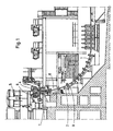
- the liquid metal passes from a ladle 5 over a distribution vessel 6 (of which in a 6-strand plant also two be present can) each through the continuous casting mold 7 (primary cooling) in a cooling chamber 8 (secondary cooling) and is by means of a support roller frame 9 in the bow guided and straight in the horizontal by a directional driver unit 10 again directed (Fig. 1).
- a distribution vessel 6 of which in a 6-strand plant also two be present can
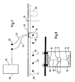
- the invention serves for non-contact measurement of the profile thickness 11 (FIG. 8) or also the entire profile shape 12 with cross-sectional shapes 13 of a billet strand 1a by means of sensors 14, which within a cross-sectional shape 13 of a billet.
- - Block, Beamblank-, slab or thin slab casting strand 1a surrounding Base frame 15 are arranged.
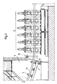
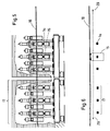
- Fig. 2 is perpendicular to the parallel strand course 16 (Fig. 3 and 4) of the shown Strand groups 17 of the base frame 15 in a trained as a carrier Rail guide 18 movable back and forth.
- a measuring device 19 with pairwise sensors fourteenth arranged.
- the sensors 14 are connected to an evaluation electronics 20.
- the rail guide 18 is in Figs. 2 and 4 outside the spray area 21st arranged.
- the internally cooled base frame 15 is by means of flexible media connections 22 (Fig. 7) to a media port 23 (for air, water and / or Lubricants) connected.
- the internally cooled base frame 15 may be made Be made of stainless steel.
- a flexible cable connection leads 24 to the evaluation electronics 20.
- the evaluation electronics 20 can as Measuring computer 26 be configured.
- the measuring computer 26 is in a switch house 27 of the Mehrstrangg matterstrom 3 (Fig. 3) housed.
- the middle 1b forms one each Measuring position 28 on the travel 29 of the base frame 15.
- the sensors 14 can therefore for scanning a profile page 1c also horizontally lying (in addition) be arranged.
- the two sensors 14 are a triangulation laser system executed.
- the method for contactless measurement of the profile thickness 11 or the profile shape 12 on individual casting strands 1 of the Mehrstrangg messstrom 3 for liquid Metals, especially for liquid steel 4, determines the profile thickness 11 or a Profile mold 12 one of the listed cross-sectional shapes 13 of each species via the sensors 14.
- the transient measuring device 19 after selecting a cast strand 1 to be measured in a measuring position 28 perpendicular to the parallel strand course 16 of the strand groups 17 of the parallel casting strands 1 and then the measuring process is triggered. It is in the transient Measuring device 19 is set to the respective center 1 b of the cast strand 1.
- the setting of the measuring position 28 can take place in a casting pause.
- the measuring device 19 in a parking position 30th (Fig. 7) outside the radiation range of the respective strand group 17 or in a shielded maintenance area 31 are brought.
- the measuring device 19 in a parking position 30th (Fig. 7) outside the radiation range of the respective strand group 17 or in a shielded maintenance area 31 are brought.
- FIG. 8 can either the entire profile form 12 of a casting strand 1 or at least one Profile page 1 c are scanned.
- Figs. 5 and 6 the process is in front view of the directional driver unit 10, the base frame 15 being dashed with the measuring device 19 is drawn. There are also the strand groups 17, 17 visible. In the same Position is the base frame 15 in Fig. 6.
- the determination of the profile thickness 11 via a corresponding signal evaluation and processing in the evaluation electronics 20 The position of the billet strand 1 a with a cross-sectional shape 13 within the base frame 15 is conditional by the used measuring principle. Each sensor 14 detects position and distance the respective profile page 1 c. Due to the used time-synchronous evaluation the signals can be independent of the cross-sectional shape 13 measurement the profile thickness 11 are made. The selected measuring method becomes thereby not impaired.
Landscapes
- Engineering & Computer Science (AREA)
- Mechanical Engineering (AREA)
- Continuous Casting (AREA)
Abstract
Description
- Fig. 1
- eine Seitenansicht einer Stranggießmaschine mit Gießbühne, Stützrollengerüst und Richt-Treiber-Einheit,
- Fig. 2
- einen aus der Seitenansicht der Fig. 1 ausgewählten Ausschnitt im vergrößerten Maßstab mit dem Stützrollengerüst, dem Grundrahmen und der Richt-Treiber-Einheit,
- Fig. 3
- einen Grundriss der Stranggießmaschine gemäß Fig. 1,
- Fig. 4
- den Ausschnitt aus Fig. 1 zu Fig. 2 im Grundriss mit dem Grundrahmen von oben gesehen,
- Fig. 5
- einen Querschnitt parallel zum Verlauf der Schienenführung für den Grundrahmen,
- Fig. 6
- eine Ansicht von oben auf die getrennt dargestellte Messeinrichtung,
- Fig. 7
- dieselbe Ansicht von oben auf die Organe der Messeinrichtung und
- Fig. 8
- eine Seitenansicht auf den Grundrahmen mit Sensoren.
- 1
- Gießstrang
- 1a
- Knüppelstrang
- 1 b
- Mitte
- 1 c
- Profilseite
- 2
- Stranggießmaschine
- 3
- Mehrstranggießanlage
- 4
- flüssiger Stahl
- 5
- Gießpfanne
- 6
- Verteilergefäß
- 7
- Stranggießkokille
- 8
- Kühlkammer
- 9
- Stützrollengerüst
- 10
- Richt-Treiber-Einheit
- 11
- Profildicke
- 12
- Profilform
- 13
- Querschnittsform
- 14
- Sensor
- 15
- Grundrahmen
- 16
- paralleler Strangverlauf
- 17
- Stranggruppe
- 18
- Schienenführung
- 19
- Messeinrichtung
- 20
- Auswerte-Elektronik
- 21
- Spritzbereich
- 22
- flexible Medienverbindung
- 23
- Medienanschluss
- 24
- flexible Kabelverbindung
- 25 26
- Mess-Computer
- 27
- Schalthaus
- 28
- Messposition
- 29
- Verfahrweg
- 30
- Parkposition
- 31
- Wartungsbereich
Claims (13)
- Verfahren zum berührungslosen Messen der Profildicke (11) und / oder der Profilform (12) an Gießsträngen (1) einer Mehrstranggießanlage (3) für flüssige Metalle, insbesondere für Stahl (4), bei dem Profildicken (11) oder Profilformen (12) eines Knüppel-, Block-, Beamblank-, Brammen- oder Dünnbrammen-Gießstranges (1) über Sensoren (14) gemessen werden,
dadurch gekennzeichnet, dass eine instationäre Messeinrichtung (19) nach Auswählen eines zu messenden Gießstrangs (1) in eine Messposition (28) senkrecht zum Verlauf einer Stranggruppe (17) der parallelen Gießstränge (1) verfahren und der Messvorgang ausgelöst wird. - Verfahren nach Anspruch 1,
dadurch gekennzeichnet, dass die instationäre Messeinrichtung (19) auf die jeweilige Mitte (1b) des Gießstranges (1) eingestellt wird. - Verfahren nach den Ansprüchen 1 und 2,
dadurch gekennzeichnet, dass das Einstellen der Messposition (28) in einer Gießpause durchgeführt wird. - Verfahren nach einem der Ansprüche 1 bis 3,
dadurch gekennzeichnet, dass zum Einstellen der Messposition (28) die Messeinrichtung (19) in eine Parkposition (30) außerhalb des Strahlungsbereichs der Stranggruppe (17) oder in einen abgeschirmten Wartungsbereich (31) verfahren wird. - Verfahren nach einem der Ansprüche 1 bis 4,
dadurch gekennzeichnet, dass entweder die gesamte Profilform (12) eines Gießstranges (1) oder zumindest eine Profilseite (1c) gemessen werden. - Einrichtung zum berührungslosen Messen der Profildicke (11) und / oder der Profilform (12) an Gießsträngen (1) einer Mehrstranggießanlage (3) für flüssige Metalle, insbesondere für flüssigen Stahl (4), mit Querschnittsformen (13) und -abmessungen eines Knüppel-, Block-, Beamblank-, Brammen- oder Dünnbrammen-Gießstranges (1) mittels Sensoren (14), die innerhalb eines die Querschnittsform (13) umgebenden Grundrahmens (15) angeordnet sind,
dadurch gekennzeichnet, dass senkrecht zum parallelen Strangverlauf (16) der Stranggruppe (17) eine Schienenführung (18) für einen innen gekühlten, hin- und herverfahrbaren Grundrahmen (15) verläuft, in dem die Messeinrichtung (19) mit den Sensoren (14) angeordnet ist, wobei die Sensoren (14) mit einer Auswerte-Elektronik (20) entfernt von den Gießsträngen (1) kommunizieren. - Einrichtung nach Anspruch 6,
dadurch gekennzeichnet, dass die Schienenführung (18) außerhalb des Spritzbereichs (21) der Kühlkammer (8) angeordnet ist. - Einrichtung nach einem der Ansprüche 6 oder 7,
dadurch gekennzeichnet, dass der innen gekühlte Grundrahmen (15) mittels flexiblen Medienverbindungen (22) an Medienanschlüsse (23) gekuppelt oder in der jeweiligen Messposition (28) über örtlich vorgesehene Kupplungen verbindbar ist. - Einrichtung nach einem der Ansprüche 6 bis 8,
dadurch gekennzeichnet, dass der innen gekühlte Grundrahmen (15) aus Edelstahl hergestellt ist. - Einrichtung nach einem der Ansprüche 6 bis 9,
dadurch gekennzeichnet, dass die zu jedem Gießstrang (1) gehörenden Messpositionen (28) mittels mechanischen Fixierungen reproduzierbar sind. - Einrichtung nach Anspruch 6,
dadurch gekennzeichnet, dass die Sensoren (14) mittels flexiblen und / oder variablen Kabelverbindungen (24) an die Auswerte-Elektronik (20) angeschlossen sind oder über eine drahtlose Funkverbindung kommunizieren. - Einrichtung nach einem der Ansprüche 6, 10 oder 11,
dadurch gekennzeichnet, dass die Auswerte-Elektronik (20) in Form eines Mess-Computers (26) im Schalthaus (27) der Stranggießmaschine (2) untergebracht ist. - Einrichtung nach einem der Ansprüche 6, 11 und 12,
dadurch gekennzeichnet, dass die Sensoren (14) in dem Grundrahmen (15) für eine beidseitige Abstandsmessung zur jeweiligen Profilseite (1c) symmetrisch paarweise gegenüberliegend angeordnet sind.
Applications Claiming Priority (2)
| Application Number | Priority Date | Filing Date | Title |
|---|---|---|---|
| DE10336444A DE10336444A1 (de) | 2003-08-08 | 2003-08-08 | Verfahren und Einrichtung zum berührungslosen Messen der Profildicke und/oder der Profilform an Gießsträngen einer Mehrstranggießanlage für flüssige Metalle, insbesondere für Stahl |
| DE10336444 | 2003-08-08 |
Publications (2)
| Publication Number | Publication Date |
|---|---|
| EP1504832A1 true EP1504832A1 (de) | 2005-02-09 |
| EP1504832B1 EP1504832B1 (de) | 2008-02-13 |
Family
ID=33547154
Family Applications (1)
| Application Number | Title | Priority Date | Filing Date |
|---|---|---|---|
| EP04014660A Expired - Lifetime EP1504832B1 (de) | 2003-08-08 | 2004-06-23 | Verfahren und Einrichtung zum berührungslosen Messen der Profildicke und/oder der Profilform an Giesssträngen einer Mehrstranggiessanlage für flüssige Metalle, insbesondere für Stahl |
Country Status (3)
| Country | Link |
|---|---|
| EP (1) | EP1504832B1 (de) |
| AT (1) | ATE385867T1 (de) |
| DE (2) | DE10336444A1 (de) |
Cited By (1)
| Publication number | Priority date | Publication date | Assignee | Title |
|---|---|---|---|---|
| EP1917115B2 (de) † | 2005-11-22 | 2018-03-14 | SMS group GmbH | Verfahren und vorrichtung zum anstellen von mindestens einem rollensegment einer strangführungseinrichtung an einen strang |
Citations (3)
| Publication number | Priority date | Publication date | Assignee | Title |
|---|---|---|---|---|
| US4311392A (en) * | 1979-09-21 | 1982-01-19 | Bridgestone Tire Company Limited | Thickness measuring apparatus for non-metallic sheet-shaped bodies |
| DE3240515A1 (de) * | 1982-10-30 | 1984-05-03 | Licentia Patent-Verwaltungs-Gmbh, 6000 Frankfurt | Einrichtung zur bestimmung der spiesskantigkeit von stranggiessknueppeln waehrend des giessprozesses |
| US5388341A (en) * | 1993-08-04 | 1995-02-14 | Data Measurement Corporation | Virtual two gauge profile system |
-
2003
- 2003-08-08 DE DE10336444A patent/DE10336444A1/de not_active Withdrawn
-
2004
- 2004-06-23 EP EP04014660A patent/EP1504832B1/de not_active Expired - Lifetime
- 2004-06-23 AT AT04014660T patent/ATE385867T1/de active
- 2004-06-23 DE DE502004006165T patent/DE502004006165D1/de not_active Expired - Lifetime
Patent Citations (3)
| Publication number | Priority date | Publication date | Assignee | Title |
|---|---|---|---|---|
| US4311392A (en) * | 1979-09-21 | 1982-01-19 | Bridgestone Tire Company Limited | Thickness measuring apparatus for non-metallic sheet-shaped bodies |
| DE3240515A1 (de) * | 1982-10-30 | 1984-05-03 | Licentia Patent-Verwaltungs-Gmbh, 6000 Frankfurt | Einrichtung zur bestimmung der spiesskantigkeit von stranggiessknueppeln waehrend des giessprozesses |
| US5388341A (en) * | 1993-08-04 | 1995-02-14 | Data Measurement Corporation | Virtual two gauge profile system |
Cited By (1)
| Publication number | Priority date | Publication date | Assignee | Title |
|---|---|---|---|---|
| EP1917115B2 (de) † | 2005-11-22 | 2018-03-14 | SMS group GmbH | Verfahren und vorrichtung zum anstellen von mindestens einem rollensegment einer strangführungseinrichtung an einen strang |
Also Published As
| Publication number | Publication date |
|---|---|
| ATE385867T1 (de) | 2008-03-15 |
| DE502004006165D1 (de) | 2008-03-27 |
| EP1504832B1 (de) | 2008-02-13 |
| DE10336444A1 (de) | 2005-03-10 |
Similar Documents
| Publication | Publication Date | Title |
|---|---|---|
| EP2024110B1 (de) | Vorrichtung zum messen der breite und/oder der bandlage eines metallbandes oder einer bramme | |
| DE69515251T2 (de) | Formen von dünnen metallurgischen Produkten zwischen zwei Zylindern | |
| EP1142653B1 (de) | Walzenkühl- und/oder Schmiervorrichtung für Kaltbandwalzwerke, insbesondere Feinband- und Folienwalzwerke | |
| EP1706233A1 (de) | Verfahren und einrichtung zum bestimmen der lage der sumpfspitze im giessstrang beim stranggiessen von flüssigen metallen, insbesondere von flüssigen stahlwerkstoffen | |
| DE102009010251A1 (de) | Vorrichtung und Verfahren zur Sekundärkühlung in einer Stranggießanlage | |
| DE19627336C1 (de) | Verfahren zum Führen eines Stranges und Strangführung | |
| WO2006037555A1 (de) | Verfahren und rollensegment zum bestimmen der kernerstarrung und/oder der sumpfspitze beim stranggiessen von metallen, insbesondere von stahlwerkstoffen | |
| DE2450405C3 (de) | Vorrichtung zur Messung des Walzenabstands in einer bogenförmigen Stranggießmaschine | |
| DE69307158T2 (de) | Verfahren und Vorrichtung zur Bestimmung der Dicke der Feuerfeststoffebeschichtung in einem Behälter für schmelzflüssiges Metall und zum Nachweis von durchdringendem Metall in der Beschichtung | |
| EP1504832B1 (de) | Verfahren und Einrichtung zum berührungslosen Messen der Profildicke und/oder der Profilform an Giesssträngen einer Mehrstranggiessanlage für flüssige Metalle, insbesondere für Stahl | |
| DE3136394C2 (de) | ||
| WO2010127820A1 (de) | Spritzbalken, strecke und verfahren zum aufbringen eines mediums auf ein produkt | |
| EP1187688B1 (de) | Automatisches verwaltungssystem für walzwerk | |
| DE69605946T2 (de) | Verfahren und vorrichtung zum schleifen insbesondere von brammen | |
| EP3069133B1 (de) | Verfahren und vorrichtung zur kontaktlosen überprüfung der beschaffenheit eines metallurgischen giessproduktes | |
| EP1486275A1 (de) | Verfahren und Stranggiessmaschine zum Grundeinstellen und Kontrollieren der Rollenspalte von Führungsrollensegmenten oder Treiberrollenpaaren | |
| DD153643A5 (de) | Einrichtung zur identifizierung von giessformeinheiten einer giessstrasse | |
| EP3663017A1 (de) | Überwachen eines verschleisszustands einer strangführungsrolle einer stranggiessanlage | |
| EP0213060B1 (de) | Verfahren und Auszieheinrichtung zum Horizontalstranggiessen von Metall, insbes. von Stahl | |
| DE19547438C2 (de) | Sensorträger | |
| EP2053351A2 (de) | Messsystem, insbesondere zur Messung von Nuten | |
| EP1543900B1 (de) | Verfahren und Stranggiessmaschine zum Grundeinstellen und Kontrollieren der Rollenspalte von Stützrollensegmenten oder Treiberrollenpaaren beim Giessen von flüssigen Metallen, insbesondere von flüssigen Stahlwerkstoffen | |
| AT411579B (de) | Verfahren und markiereinrichtung für ein stranggussprofil | |
| EP3784423B1 (de) | Schrägwalzwerk mit hydraulischer walzenanstellung | |
| EP0463427B1 (de) | Honmachine |
Legal Events
| Date | Code | Title | Description |
|---|---|---|---|
| PUAI | Public reference made under article 153(3) epc to a published international application that has entered the european phase |
Free format text: ORIGINAL CODE: 0009012 |
|
| 17P | Request for examination filed |
Effective date: 20040624 |
|
| AK | Designated contracting states |
Kind code of ref document: A1 Designated state(s): AT BE BG CH CY CZ DE DK EE ES FI FR GB GR HU IE IT LI LU MC NL PL PT RO SE SI SK TR |
|
| AX | Request for extension of the european patent |
Extension state: AL HR LT LV MK |
|
| RIN1 | Information on inventor provided before grant (corrected) |
Inventor name: ALFRED ARLT Inventor name: DR.STEPHAN FELDHAUS Inventor name: FEST, THOMAS Inventor name: JOHANNES ERIC FROESE Inventor name: WEYER, AXEL |
|
| AKX | Designation fees paid |
Designated state(s): AT BE BG CH CY CZ DE DK EE ES FI FR GB GR HU IE IT LI LU MC NL PL PT RO SE SI SK TR |
|
| GRAP | Despatch of communication of intention to grant a patent |
Free format text: ORIGINAL CODE: EPIDOSNIGR1 |
|
| GRAA | (expected) grant |
Free format text: ORIGINAL CODE: 0009210 |
|
| GRAS | Grant fee paid |
Free format text: ORIGINAL CODE: EPIDOSNIGR3 |
|
| AK | Designated contracting states |
Kind code of ref document: B1 Designated state(s): AT BE BG CH CY CZ DE DK EE ES FI FR GB GR HU IE IT LI LU MC NL PL PT RO SE SI SK TR |
|
| REG | Reference to a national code |
Ref country code: GB Ref legal event code: FG4D Free format text: NOT ENGLISH |
|
| REG | Reference to a national code |
Ref country code: CH Ref legal event code: EP |
|
| REG | Reference to a national code |
Ref country code: IE Ref legal event code: FG4D Free format text: LANGUAGE OF EP DOCUMENT: GERMAN |
|
| REF | Corresponds to: |
Ref document number: 502004006165 Country of ref document: DE Date of ref document: 20080327 Kind code of ref document: P |
|
| PG25 | Lapsed in a contracting state [announced via postgrant information from national office to epo] |
Ref country code: ES Free format text: LAPSE BECAUSE OF FAILURE TO SUBMIT A TRANSLATION OF THE DESCRIPTION OR TO PAY THE FEE WITHIN THE PRESCRIBED TIME-LIMIT Effective date: 20080524 Ref country code: FI Free format text: LAPSE BECAUSE OF FAILURE TO SUBMIT A TRANSLATION OF THE DESCRIPTION OR TO PAY THE FEE WITHIN THE PRESCRIBED TIME-LIMIT Effective date: 20080213 |
|
| NLV1 | Nl: lapsed or annulled due to failure to fulfill the requirements of art. 29p and 29m of the patents act | ||
| PG25 | Lapsed in a contracting state [announced via postgrant information from national office to epo] |
Ref country code: PL Free format text: LAPSE BECAUSE OF FAILURE TO SUBMIT A TRANSLATION OF THE DESCRIPTION OR TO PAY THE FEE WITHIN THE PRESCRIBED TIME-LIMIT Effective date: 20080213 Ref country code: SI Free format text: LAPSE BECAUSE OF FAILURE TO SUBMIT A TRANSLATION OF THE DESCRIPTION OR TO PAY THE FEE WITHIN THE PRESCRIBED TIME-LIMIT Effective date: 20080213 |
|
| REG | Reference to a national code |
Ref country code: IE Ref legal event code: FD4D |
|
| PG25 | Lapsed in a contracting state [announced via postgrant information from national office to epo] |
Ref country code: PT Free format text: LAPSE BECAUSE OF FAILURE TO SUBMIT A TRANSLATION OF THE DESCRIPTION OR TO PAY THE FEE WITHIN THE PRESCRIBED TIME-LIMIT Effective date: 20080714 Ref country code: DK Free format text: LAPSE BECAUSE OF FAILURE TO SUBMIT A TRANSLATION OF THE DESCRIPTION OR TO PAY THE FEE WITHIN THE PRESCRIBED TIME-LIMIT Effective date: 20080213 Ref country code: NL Free format text: LAPSE BECAUSE OF FAILURE TO SUBMIT A TRANSLATION OF THE DESCRIPTION OR TO PAY THE FEE WITHIN THE PRESCRIBED TIME-LIMIT Effective date: 20080213 Ref country code: SE Free format text: LAPSE BECAUSE OF FAILURE TO SUBMIT A TRANSLATION OF THE DESCRIPTION OR TO PAY THE FEE WITHIN THE PRESCRIBED TIME-LIMIT Effective date: 20080513 Ref country code: IE Free format text: LAPSE BECAUSE OF FAILURE TO SUBMIT A TRANSLATION OF THE DESCRIPTION OR TO PAY THE FEE WITHIN THE PRESCRIBED TIME-LIMIT Effective date: 20080213 Ref country code: SK Free format text: LAPSE BECAUSE OF FAILURE TO SUBMIT A TRANSLATION OF THE DESCRIPTION OR TO PAY THE FEE WITHIN THE PRESCRIBED TIME-LIMIT Effective date: 20080213 Ref country code: CZ Free format text: LAPSE BECAUSE OF FAILURE TO SUBMIT A TRANSLATION OF THE DESCRIPTION OR TO PAY THE FEE WITHIN THE PRESCRIBED TIME-LIMIT Effective date: 20080213 |
|
| PG25 | Lapsed in a contracting state [announced via postgrant information from national office to epo] |
Ref country code: RO Free format text: LAPSE BECAUSE OF FAILURE TO SUBMIT A TRANSLATION OF THE DESCRIPTION OR TO PAY THE FEE WITHIN THE PRESCRIBED TIME-LIMIT Effective date: 20080213 |
|
| EN | Fr: translation not filed | ||
| PLBE | No opposition filed within time limit |
Free format text: ORIGINAL CODE: 0009261 |
|
| STAA | Information on the status of an ep patent application or granted ep patent |
Free format text: STATUS: NO OPPOSITION FILED WITHIN TIME LIMIT |
|
| BERE | Be: lapsed |
Owner name: SMS DEMAG A.G. Effective date: 20080630 |
|
| 26N | No opposition filed |
Effective date: 20081114 |
|
| PG25 | Lapsed in a contracting state [announced via postgrant information from national office to epo] |
Ref country code: MC Free format text: LAPSE BECAUSE OF NON-PAYMENT OF DUE FEES Effective date: 20080630 |
|
| REG | Reference to a national code |
Ref country code: CH Ref legal event code: PL |
|
| PG25 | Lapsed in a contracting state [announced via postgrant information from national office to epo] |
Ref country code: BE Free format text: LAPSE BECAUSE OF NON-PAYMENT OF DUE FEES Effective date: 20080630 |
|
| PG25 | Lapsed in a contracting state [announced via postgrant information from national office to epo] |
Ref country code: FR Free format text: LAPSE BECAUSE OF FAILURE TO SUBMIT A TRANSLATION OF THE DESCRIPTION OR TO PAY THE FEE WITHIN THE PRESCRIBED TIME-LIMIT Effective date: 20081205 Ref country code: BG Free format text: LAPSE BECAUSE OF FAILURE TO SUBMIT A TRANSLATION OF THE DESCRIPTION OR TO PAY THE FEE WITHIN THE PRESCRIBED TIME-LIMIT Effective date: 20080513 Ref country code: EE Free format text: LAPSE BECAUSE OF FAILURE TO SUBMIT A TRANSLATION OF THE DESCRIPTION OR TO PAY THE FEE WITHIN THE PRESCRIBED TIME-LIMIT Effective date: 20080213 |
|
| PG25 | Lapsed in a contracting state [announced via postgrant information from national office to epo] |
Ref country code: LI Free format text: LAPSE BECAUSE OF NON-PAYMENT OF DUE FEES Effective date: 20080630 Ref country code: CH Free format text: LAPSE BECAUSE OF NON-PAYMENT OF DUE FEES Effective date: 20080630 |
|
| PG25 | Lapsed in a contracting state [announced via postgrant information from national office to epo] |
Ref country code: CY Free format text: LAPSE BECAUSE OF FAILURE TO SUBMIT A TRANSLATION OF THE DESCRIPTION OR TO PAY THE FEE WITHIN THE PRESCRIBED TIME-LIMIT Effective date: 20080213 |
|
| PG25 | Lapsed in a contracting state [announced via postgrant information from national office to epo] |
Ref country code: HU Free format text: LAPSE BECAUSE OF FAILURE TO SUBMIT A TRANSLATION OF THE DESCRIPTION OR TO PAY THE FEE WITHIN THE PRESCRIBED TIME-LIMIT Effective date: 20080814 Ref country code: LU Free format text: LAPSE BECAUSE OF NON-PAYMENT OF DUE FEES Effective date: 20080623 |
|
| PG25 | Lapsed in a contracting state [announced via postgrant information from national office to epo] |
Ref country code: TR Free format text: LAPSE BECAUSE OF FAILURE TO SUBMIT A TRANSLATION OF THE DESCRIPTION OR TO PAY THE FEE WITHIN THE PRESCRIBED TIME-LIMIT Effective date: 20080213 |
|
| PG25 | Lapsed in a contracting state [announced via postgrant information from national office to epo] |
Ref country code: GR Free format text: LAPSE BECAUSE OF FAILURE TO SUBMIT A TRANSLATION OF THE DESCRIPTION OR TO PAY THE FEE WITHIN THE PRESCRIBED TIME-LIMIT Effective date: 20080514 |
|
| PGFP | Annual fee paid to national office [announced via postgrant information from national office to epo] |
Ref country code: GB Payment date: 20150618 Year of fee payment: 12 Ref country code: DE Payment date: 20150619 Year of fee payment: 12 |
|
| REG | Reference to a national code |
Ref country code: DE Ref legal event code: R082 Ref document number: 502004006165 Country of ref document: DE Representative=s name: HEMMERICH & KOLLEGEN, DE Ref country code: DE Ref legal event code: R081 Ref document number: 502004006165 Country of ref document: DE Owner name: SMS GROUP GMBH, DE Free format text: FORMER OWNER: SMS SIEMAG AKTIENGESELLSCHAFT, 40237 DUESSELDORF, DE |
|
| PGFP | Annual fee paid to national office [announced via postgrant information from national office to epo] |
Ref country code: IT Payment date: 20150622 Year of fee payment: 12 Ref country code: AT Payment date: 20150619 Year of fee payment: 12 |
|
| REG | Reference to a national code |
Ref country code: DE Ref legal event code: R119 Ref document number: 502004006165 Country of ref document: DE |
|
| REG | Reference to a national code |
Ref country code: AT Ref legal event code: MM01 Ref document number: 385867 Country of ref document: AT Kind code of ref document: T Effective date: 20160623 |
|
| GBPC | Gb: european patent ceased through non-payment of renewal fee |
Effective date: 20160623 |
|
| PG25 | Lapsed in a contracting state [announced via postgrant information from national office to epo] |
Ref country code: DE Free format text: LAPSE BECAUSE OF NON-PAYMENT OF DUE FEES Effective date: 20170103 |
|
| PG25 | Lapsed in a contracting state [announced via postgrant information from national office to epo] |
Ref country code: AT Free format text: LAPSE BECAUSE OF NON-PAYMENT OF DUE FEES Effective date: 20160623 Ref country code: GB Free format text: LAPSE BECAUSE OF NON-PAYMENT OF DUE FEES Effective date: 20160623 |
|
| PG25 | Lapsed in a contracting state [announced via postgrant information from national office to epo] |
Ref country code: IT Free format text: LAPSE BECAUSE OF NON-PAYMENT OF DUE FEES Effective date: 20160623 |