EP1916220A1 - Mobiler Hubkran mit variabel positionierbarem Gegengewicht - Google Patents
Mobiler Hubkran mit variabel positionierbarem Gegengewicht Download PDFInfo
- Publication number
- EP1916220A1 EP1916220A1 EP07254071A EP07254071A EP1916220A1 EP 1916220 A1 EP1916220 A1 EP 1916220A1 EP 07254071 A EP07254071 A EP 07254071A EP 07254071 A EP07254071 A EP 07254071A EP 1916220 A1 EP1916220 A1 EP 1916220A1
- Authority
- EP
- European Patent Office
- Prior art keywords
- counterweight
- rotating bed
- crane
- mast
- hydraulic cylinder
- Prior art date
- Legal status (The legal status is an assumption and is not a legal conclusion. Google has not performed a legal analysis and makes no representation as to the accuracy of the status listed.)
- Granted
Links
- 238000000034 method Methods 0.000 claims abstract description 21
- 230000002452 interceptive effect Effects 0.000 claims description 3
- 230000006835 compression Effects 0.000 claims description 2
- 238000007906 compression Methods 0.000 claims description 2
- 230000008901 benefit Effects 0.000 description 6
- 230000005484 gravity Effects 0.000 description 4
- 230000007246 mechanism Effects 0.000 description 4
- 238000012986 modification Methods 0.000 description 4
- 230000004048 modification Effects 0.000 description 4
- 230000000712 assembly Effects 0.000 description 1
- 238000000429 assembly Methods 0.000 description 1
- 230000008859 change Effects 0.000 description 1
- 238000006243 chemical reaction Methods 0.000 description 1
- 238000010276 construction Methods 0.000 description 1
- 230000003467 diminishing effect Effects 0.000 description 1
- 238000002360 preparation method Methods 0.000 description 1
- 230000009467 reduction Effects 0.000 description 1
- 238000005096 rolling process Methods 0.000 description 1
Images


Classifications
-
- B—PERFORMING OPERATIONS; TRANSPORTING
- B66—HOISTING; LIFTING; HAULING
- B66C—CRANES; LOAD-ENGAGING ELEMENTS OR DEVICES FOR CRANES, CAPSTANS, WINCHES, OR TACKLES
- B66C23/00—Cranes comprising essentially a beam, boom, or triangular structure acting as a cantilever and mounted for translatory of swinging movements in vertical or horizontal planes or a combination of such movements, e.g. jib-cranes, derricks, tower cranes
- B66C23/62—Constructional features or details
- B66C23/72—Counterweights or supports for balancing lifting couples
- B66C23/74—Counterweights or supports for balancing lifting couples separate from jib
- B66C23/76—Counterweights or supports for balancing lifting couples separate from jib and movable to take account of variations of load or of variations of length of jib
-
- B—PERFORMING OPERATIONS; TRANSPORTING
- B66—HOISTING; LIFTING; HAULING
- B66C—CRANES; LOAD-ENGAGING ELEMENTS OR DEVICES FOR CRANES, CAPSTANS, WINCHES, OR TACKLES
- B66C23/00—Cranes comprising essentially a beam, boom, or triangular structure acting as a cantilever and mounted for translatory of swinging movements in vertical or horizontal planes or a combination of such movements, e.g. jib-cranes, derricks, tower cranes
- B66C23/88—Safety gear
- B66C23/90—Devices for indicating or limiting lifting moment
-
- B—PERFORMING OPERATIONS; TRANSPORTING
- B66—HOISTING; LIFTING; HAULING
- B66C—CRANES; LOAD-ENGAGING ELEMENTS OR DEVICES FOR CRANES, CAPSTANS, WINCHES, OR TACKLES
- B66C23/00—Cranes comprising essentially a beam, boom, or triangular structure acting as a cantilever and mounted for translatory of swinging movements in vertical or horizontal planes or a combination of such movements, e.g. jib-cranes, derricks, tower cranes
- B66C23/18—Cranes comprising essentially a beam, boom, or triangular structure acting as a cantilever and mounted for translatory of swinging movements in vertical or horizontal planes or a combination of such movements, e.g. jib-cranes, derricks, tower cranes specially adapted for use in particular purposes
- B66C23/20—Cranes comprising essentially a beam, boom, or triangular structure acting as a cantilever and mounted for translatory of swinging movements in vertical or horizontal planes or a combination of such movements, e.g. jib-cranes, derricks, tower cranes specially adapted for use in particular purposes with supporting couples provided by walls of buildings or like structures
- B66C23/24—Mobile wall cranes
Definitions
- the present application relates to lift cranes, and particularly to mobile lift cranes having a counterweight that can be moved to different positions in an effort to balance a load on the crane.
- Lift cranes typically include counterweights to help balance the crane when the crane lifts a load.
- the counterweight on the rear of the crane is so large that the carbody is also equipped with counterweight to prevent backward tipping when no load is being lifted.
- an extra counterweight attachment such as a counterweight trailer, is sometimes added to the crane to further enhance the lift capacities of the mobile lift crane. Since the load is often moved in and out with respect to the center of rotation of the crane, and thus generates different moments throughout a crane pick, move and set operation, it is advantageous if the counterweight, including any extra counterweight attachments, can also be moved forward and backward with respect to the center of rotation of the crane. In this way a smaller amount of counterweight can be utilized than would be necessary if the counterweight had to be kept at a fixed distance.
- any extra counterweight attachments also need to be mobile.
- the extra counterweight attachment also has to be able to travel over the ground. This means that the ground has to be prepared and cleared, and often timbers put in place, for swing or travel of the extra counterweight unit.
- a typical example of the forgoing is a Terex Demag CC8800 crane with a Superlift attachment.
- This crane includes 100 metric tonne of carbody counterweight, 280 metric tonne of crane counterweight, and 640 metric tonne on an extra counterweight attachment, for a total of 1020 metric tonne of counterweight.
- the extra counterweight can be moved in and out by a telescoping member.
- This crane has a maximum rated load moment of 23,500 metric tonne-meters. Thus the ratio of maximum rated load moment to total weight of the counterweight is only 23.04.
- the invention is a mobile lift crane comprising a carbody having moveable ground engaging members; a rotating bed rotatably connected to the carbody such that the rotating bed can swing with respect to the ground engaging members; a boom pivotally mounted on a front portion of the rotating bed; a mast mounted at its first end on the rotating bed; a backhitch connected between the mast and a rear portion of the rotating bed; a moveable counterweight unit; at least one hydraulic cylinder; and at least one arm pivotally connected at a first end to the rotating bed and at a second end to the hydraulic cylinder.
- the arm and hydraulic cylinder are connected between the rotating bed and the counterweight unit such that extension and retraction of the hydraulic cylinder changes the position of the counterweight unit compared to the rotating bed.
- the invention is a mobile lift crane comprising a carbody having moveable ground engaging members; a rotating bed rotatably connected to the carbody such that the rotating bed can swing with respect to the ground engaging members; a boom pivotally mounted on a front portion of the rotating bed; a mast mounted at its first end on the rotating bed at a fixed angle compared to the plane of rotation of the rotating bed; a moveable counterweight unit suspended from a tension member connected at second end of the mast; and a counterweight movement structure connected between the rotating bed and the counterweight unit such that the counterweight unit may be moved to and held at a position in front of the top of the mast and moved to and held at a position rearward of the top of the mast.
- a third aspect of the invention is a mobile lift crane comprising a carbody having moveable ground engaging members; a rotating bed rotatably connected about an axis of rotation to the carbody such that the rotating bed can swing with respect to the ground engaging members; a boom pivotally mounted on a front portion of the rotating bed; a mast mounted at its first end on the rotating bed; a moveable counterweight unit; and a counterweight movement structure connected between the rotating bed and the counterweight unit such that the counterweight unit may be moved to and held at both a forward position and a rearward position; wherein the crane has a total amount of counterweight of at least 250 metric tonne and a maximum rated load moment of at least 6,250 metric tonne-meters, and the ratio of the maximum rated load moment to the total weight of all of the counterweight on the crane is at least 25.
- a fourth aspect of the invention is a method of operating a mobile lift crane.
- the lift crane comprises a carbody having moveable ground engaging members; a rotating bed rotatably connected to the carbody such that the rotating bed can swing with respect to the ground engaging members; a boom pivotally mounted on a front portion of the rotating bed, with a hoist line extending therefrom; a mast mounted at its first end on the rotating bed; and a moveable counterweight unit.
- the method comprises the steps of positioning the counterweight forward of a point directly below the top of the mast when no load is on the hook; and positioning the counterweight reward of the top of the mast when the hoist line is supporting a load; wherein the moveable counterweight is never supported by the ground during crane pick, move and set operations other than indirectly by the ground engaging members on the carbody.
- the invention is a method of operating a mobile lift crane.
- the lift crane comprises a carbody having moveable ground engaging members; a rotating bed rotatably connected to the carbody such that the rotating bed can swing with respect to the ground engaging members; a boom pivotally mounted on a front portion of the rotating bed, with a hoist line extending therefrom; a mast mounted at its first end on the rotating bed; at least one hydraulic cylinder; and a moveable counterweight unit.
- the method comprises the step of performing a pick, move and set operation with a load wherein the moveable counterweight is moved toward and away from the front portion of the rotating bed by extending and retracting the hydraulic cylinder during the pick, move and set operation to help counterbalance the load, but wherein the counterweight is never supported by the ground other than indirectly by the ground engaging members on the carbody.
- a single large counterweight can be positioned far forward such that it produces very little backward moment on the crane when no load is on the hook.
- the carbody need not have extra counterweight attached to it.
- This large counterweight can be positioned far backward so that it can counterbalance a heavy load.
- a 700 metric tonne counterweight can be used as the only counterweight on the crane, and the crane can still lift loads equivalent to those of the Terex Demag CC8800 Superlift with 1020 metric tonne of counterweight.
- Another advantage of the preferred embodiment of the invention is that the counterweight need not be set on the ground when the crane sets its load. There is no extra counterweight unit requiring a trailer, and the limitations of having to prepare the ground for such a trailer.
- Figure 1 is a side elevational view of a first embodiment of a mobile lift crane with a variable position counterweight, shown with the counterweight in a far forward position.
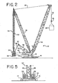
- Figure 2 is a side elevational view of the mobile lift crane of Figure 1 with the counterweight in a mid position.
- Figure 3 is a side elevational view of the mobile lift crane of Figure 1 with the counterweight in a rear position.
- Figure 4 is a partial top plan view of the crane of Figure 1 with the counterweight in a rear position.
- Figure 5 is a partial rear elevational view of the crane of Figure 1.
- Figure 6 is a side elevational view of a second embodiment of a mobile lift crane of the present invention, with dashed lines showing the counterweight in various positions.
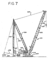
- Figure 7 is a side elevational view of a third embodiment of a mobile lift crane of the present invention, with dashed lines showing the counterweight in various positions.
- Figure 8 is a side elevational view of a fourth embodiment of a mobile lift crane of the present invention, with dashed lines showing the counterweight in a second position.
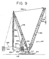
- Figure 9 is a side elevational view of a fifth embodiment of a mobile lift crane of the present invention, with dashed lines showing the counterweight in a second position.
- Figure 10 is a side elevational view of a sixth embodiment of a mobile lift crane of the present invention, with dashed lines showing the counterweight in a second position.
- Figure 11 is a partial rear elevational view of the crane of Figure 10.
- Figure 12 is a cross-sectional view taken along line 12-12 of Figure 11.
- Figure 13 is a cross-sectional view taken along line 13-13 of Figure 11.
- Figure 14 is a cross-sectional view taken along line 14-14 of Figure 11.
- the front of the rotating bed is defined as the portion of the rotating bed that is between the axis of rotation of the rotating bed and the position of the load when a load is being lifted.
- the rear portion of the rotating bed includes everything opposite the axis of rotation from the front of the rotating bed.
- the terms "front” and “rear” (or modifications thereof such as “rearward") referring to other parts of the rotating bed, or things connected thereto, such as the mast, are taken from this same context, regardless of the actual position of the rotating bed with respect to the ground engaging members.
- the position of the counterweight unit is defined as the center of gravity of the combination of all counterweight elements and any holding tray to which the counterweights are attached, or otherwise move in conjunction with. All counterweight units on a crane that are tied together so as to always move simultaneously are treated as a single counterweight for purposes of determining the center of gravity.
- the top of the mast is defined as the furthest back position on the mast from which any line or tension member supported from the mast is suspended. If no line or tension member is supported from the mast, then the top of the mast is the position to which any backhitch is attached.
- the moveable ground engaging members are defined as members that are designed to remain engaged with the ground while the crane moves over the ground, such as tires or crawlers, but does not include ground engaging members that are designed to be stationary with respect to the ground, or be lifted from contact with the ground when they are moved, such as a ring on a ring supported crane.
- the term "move" when referring to a crane operation includes movement of the crane with respect to the ground. This can be either a travel operation, where the crane traverses a distance over the ground on its ground engaging members, a swing operation, in which the rotating bed rotates with respect to the ground, or combinations of travel and swing operations.
- the mobile lift crane 10 includes lower works, also referred to as a carbody 12, and moveable ground engaging members in the form of crawlers 14 and 16.
- crawlers 14 and 16 There are of course two front crawlers 14 and two rear crawlers 16, only one each of which can be seen from the side view of Figure 1. The other set of crawlers can be seen in the top view of Figure 4.
- Figures 4 and 5 are simplified for sake of clarity, and do not show the boom, mast, and backhitch.
- the ground engaging members could be just one set of crawlers, one crawler on each side. Of course additional crawlers than those shown, or other ground engaging members such as tires, can be used.
- a rotating bed 20 is rotatably connected to the carbody 12 such that the rotating bed can swing with respect to the ground engaging members.
- the rotating bed is mounted to the carbody 12 with a slewing ring, such that the rotating bed 20 can swing about an axis with respect to the ground engaging members 14, 16.
- the rotating bed supports a boom 22 pivotally mounted on a front portion of the rotating bed; a mast 28 mounted at its first end on the rotating bed; a backhitch 30 connected between the mast and a rear portion of the rotating bed; and a moveable counterweight unit having counterweights 34 on a support member 33.
- the counterweights may be in the form of multiple stacks of individual counterweight members on the support member 33 as shown in Figure 5.
- Boom hoist rigging 25 between the top of mast 28 and boom 22 is used to control the boom angle and transfers load so that the counterweight can be used to balance a load lifted by the crane.
- a hoist line 24 extends from the boom 22, supporting a hook 26.
- the rotating bed 20 may also includes other elements commonly found on a mobile lift crane, such as an operator's cab and hoist drums for the rigging 25 and hoist line 24.
- the boom 22 may comprise a luffing jib pivotally mounted to the top of the main boom, or other boom configurations.
- the backhitch 30 is connected adjacent the top of the mast 28.
- the backhitch 30 may comprise a lattice member designed to carry both compression and tension loads as shown in Figure 1. In the crane 10, the mast is held at a fixed angle with respect to the rotating bed during crane operations, such as a pick, move and set operation.
- the counterweight unit is moveable with respect to the rest of the rotating bed 20.
- a tension member 32 connected adjacent the top of the mast supports the counterweight unit in a suspended mode.
- a counterweight movement structure is connected between the rotating bed and the counterweight unit such that the counterweight unit may be moved to and held at a first position in front of the top of the mast, and moved to and held at a second position rearward of the top of the mast.
- At least one hydraulic cylinder 38 and at least one arm pivotally connected at a first end to the rotating bed and at a second end to the hydraulic cylinder are used in the counterweight movement structure of crane 10 to change the position of the counterweight.
- the arm and hydraulic cylinder 38 are connected between the rotating bed and the counterweight unit such that extension and retraction of the hydraulic cylinder changes the position of the counterweight unit compared to the rotating bed.
- the at least one arm preferably comprises a pivot frame 40 and a rear arm 36.
- the rear arm 36 actually has both left and right members ( Figures 4 and 5), only one of which can be seen in Figure 1, and the hydraulic cylinder comprises two cylinders that move in tandem.
- the following discussion only refers to one cylinder 38 and one arm 36 for sake of simplicity.
- the pivot frame 40 is connected between the rotating bed 20 and hydraulic cylinder 38, and the rear arm 36 is connected between the pivot frame 40 and the counterweight unit.
- a trunion 37 is used to connect the rear arm 36 and pivot frame 40.
- the hydraulic cylinder 38 is pivotally connected to the rotating bed 20 on a support frame 42 which elevates the hydraulic cylinder 38 to a point so that the geometry of the cylinder 38, pivot frame 40 and rear arm 36 can move the counterweight through its entire range of motion. In this manner the cylinder 38 causes the rear arm 36 to move the counterweight unit when the cylinder is retracted and extended.
- Figure 1 shows the counterweight unit in its most forward position
- Figure 2 shows the hydraulic cylinder 38 partially extended, which moves the counterweight unit to a mid position, such as when a first load 29 is suspended from the hook 26.
- Figures 3 and 4 show the cylinder 38 fully extended, which moves the counterweight unit to its most rearward position, such as when a larger load 31 is suspended from the hook, or the boom is pivoted forward to extend the load further from the rotating bed.
- the counterweight is positioned forward of a point directly below the top of the mast when no load is on the hoist line; and the counterweight is positioned reward of the top of the mast when the hoist line supports a load.
- no load on the hoist line is used in its common meaning of no extra lifted load.
- the hook and any associated hook block may have a significant weight and apply tension to the hoist line even when no load is on the hoist line.
- the moveable counterweight is never supported by the ground during crane operations.
- the crane can performing a pick, move and set operation with a load wherein the moveable counterweight is moved toward and away from the front portion of the rotating bed by extending and retracting the hydraulic cylinder during the operation to help counterbalance the load, but the counterweight is never supported by the ground other than indirectly by the ground engaging members on the carbody.
- the single moveable counterweight unit is the only functional counterweight on the crane.
- the carbody is not provided with any separate functional counterweight.
- FIG. 6 shows a second embodiment of a crane 110 of the present invention.
- crane 110 includes a carbody 112, crawlers 114 and 116, a rotating bed 120, boom 122, boom hoist rigging 125, a load hoist line 124, a hook 126, a mast 128, a backhitch 130, a tension member 132 and a counterweight unit 134.
- the primary difference between the crane 110 compared to crane 10 is the configuration of the cylinder and arm used to move the counterweight unit.
- crane 110 there are two hydraulic cylinders 136 and 138.
- cylinder 138 is pivotally connected to the rotating bed 120.
- arm 140 is pivotally connected at one end to the rotating bed and at its other end to the cylinder 138.
- the second hydraulic cylinder 136 is connected between the arm and the counterweight unit, as the rear arm 36 was in crane 10.
- the counterweight unit can be moved between a far forward position, when both hydraulic cylinders are retracted, to mid and far rearward positions (shown in phantom lines) when, respectively, the rear cylinder 136 is extended, and when both cylinders are fully extended.
- FIG. 7 shows a third embodiment of a crane 210.
- crane 210 includes a carbody 212, crawlers 214, a rotating bed 220, boom 222, boom hoist rigging 225, a load hoist line 224, a hook 226, a mast 228, a backhitch 230, a tension member 232 and a counterweight unit 234.
- This crane is different than cranes 10 and 110 in that it has a second counterweight unit 237 which is supported directly on the rotating bed. Also, instead of having an arm and a hydraulic cylinder to move the counterweight unit 234, it has only one hydraulic cylinder 236.
- the cylinder 236 is only indirectly connected to the rotating bed, as it is connected to the second counterweight unit which is supported on the rotating bed. In this fashion, when the second counterweight unit 237 is moved forward and backward, the counterweight unit 234 is also moved.
- the hydraulic cylinder 236 can be extended to move the counterweight 234 even further away from the centerline of rotation of the rotating bed, as shown in phantom lines.
- FIG 8 shows a fourth embodiment of a crane 310 of the present invention.
- crane 310 includes a carbody 312, crawlers 314, rotating bed 320, boom 322, boom hoist rigging 325, a load hoist line 324, a hook 326, a mast 328, a backhitch 330, a tension member 332 and a counterweight 334.
- the primary difference between the crane 310 compared to crane 10 is that only the hydraulic cylinder 336 is used to move the counterweight unit, and no pivoting arm is employed.
- cylinder 336 is pivotally connected to the rotating bed 320.
- the hydraulic cylinder 336 is connected to the counterweight unit, in this case indirectly by being connected to tension member 332.
- the counterweight unit can be moved between a far forward position (shown in phantom lines) when the hydraulic cylinder 336 is fully extended in one direction.
- the counterweight is moved to a mid position by retracting the cylinder 336.
- the counterweight is moved into a far rearward position when the cylinder 336 is again fully extended.
- FIG 9 shows a fifth embodiment of a crane 410 of the present invention.
- crane 410 includes a carbody 412, crawlers 414 and 416, a rotating bed 420, boom 422, boom hoist rigging 425, a load hoist line 424, a hook 426, a mast 428, a backhitch 430, a tension member 432 and a counterweight unit 434.
- the primary difference between the crane 410 compared to crane 10 is the configuration of the cylinder and arms used to move the counterweight unit, and the fact that the counterweight is moved backward by retracting the cylinder.
- the hydraulic cylinder 436 is pivotally connected to the rotating bed, but at a point behind where the arm 438 connects to the rotating bed.
- Arm 438 is pivotally connected at one end to the rotating bed and at its other end to the cylinder 436.
- a second arm 440 is connected between the arm 438 and the counterweight unit 434, as the rear arm 36 was in crane 10.
- the counterweight unit can be moved between a far forward position, when the hydraulic cylinder 436 is fully extended, to a far rearward position (shown in phantom lines) when the cylinder 436 is fully retracted.
- FIGS 10-14 show a sixth embodiment of a crane 510 of the present invention.
- crane 510 includes a carbody 512, crawlers 514 and 516, a rotating bed 520, boom 522, boom hoist rigging 525, a load hoist line 524, a hook 526, a mast 528, a backhitch 530, a tension member 532 and a counterweight unit 534.
- the primary difference between the crane 510 compared to crane 10 is the configuration and placement of the backhitch, and the geometry of the arms 538.
- Arms 538 are not straight like arms 38 of crane 10, but rather have an angled portion 539 at the end that connects to the pivot frame 540.
- the rotating bed is shortened, and hence the point on the rotating bed where the backhitch 530 is connected is forward of the point where the mast and backhitch connect, which causes the backhitch to be at an angle from the axis of rotation of the rotating bed.
- This angle may be between about 10° and about 20°.
- the preferred angle is about 16°.
- the backhitch 530 and tension member 532 are not connected at the very top of the mast 528, they are both still connected adjacent the top of the mast.
- the backhitch 530 has an A-frame configuration, with two spaced apart legs 542 and 544 and a central upstanding member 546.
- the lattice connections 552 of the upstanding member 546 are shown in Figure 12.
- the lattice connections 554 of the legs 542 and 544 are shown in Figure 13.
- Figure 14 shows the lattice connections 556 used to construct the pivot frame 540.
- the legs 542 and 544 are spaced apart so that arms 538 and pivot frame 540 can fit between legs 542 and 544 of the backhitch 530 as the counterweight 534 swings outwardly.
- the top lattice member of the pivot frame 40 is spaced down low enough so that when the pivot frame 40 is in the position seen in Figure 3, the ends of the pivot frame can straddle the connection of the backhitch 30 to the rotating bed 20 without the lattice work of the pivot frame 40 contacting the backhitch.
- the counterweight unit 534 can be moved between a far forward position, when the hydraulic cylinder 536 is fully retracted, to a far rearward position (shown in phantom lines) when the cylinder 536 is fully extended.
- the A-frame structure permits the backhitch to be connected up closer to the centerline of rotation without interfering with the movement of the pivot frame 540 and arms 538. Having the backhitch connect at this closer position allows for the rotating bed to be shortened compared to crane 10.
- the counterweight unit is supported by the mast and the positioning mechanism at all times. There is no need for a separate wagon to support counterweight when less than the rated capacity is applied to the hook. Compared to the case of a free hanging counterweight as is used in some prior art mobile lift cranes, there is no need to set the counterweight unit on the ground. As a result, there is much less ground preparation needed for operation of the crane 10. This is a huge advantage over the systems presently in the field, in which the wagons are always in place and must be part of the lift planning with or without load on the hook. Frequently obstacles on the construction site make it difficult to position the crane and wagon.
- the counterweight movement structure will generally be able to move the counterweight over a distance of at least 10 meters, and preferably at least 20 meters, depending on the crane size.
- the hydraulic cylinder 38 will preferably have a stroke of at least 5 meters. For the geometry shown, this results in the center of gravity of the counterweight unit being able to be moved to a distance of 28 meters (90 feet) from the center of rotation of the rotating bed. Alternatively, when the cylinder 38 is fully retracted, the center of gravity of the counterweight unit is only 7 meters (23 feet) from the center of rotation. This forward position can be even shorter, depending on the geometry of the positioning mechanism.
- the counterweight movement structure can move the counterweight to a position within 7 meters of the axis of rotation and to a position of at least 28 meters away from the axis of rotation.
- the counterweight movement structure can move the counterweight over a distance of at least 22 meters with a cylinder stroke of only 5.6 meters. With this configuration, the counterweight can be moved to a position within about 6 meters of the axis of rotation and to a position of at least 28 meters away from the axis of rotation.
- the counterweight movement structure can move and hold the counterweight at a position forward of the top of the mast such that the tension member is at an angle of over 5° compared to the axis of rotation, preferably over 10°, and more preferably over 13°.
- the tension member is at an angle of at least 5°, preferably at least 10°, and more preferably over 15° compared the axis of rotation.
- the extension of the cylinder 38 can be controlled by a computer to move the counterweight unit automatically to a position needed to counterbalance a load being lifted, or a luffing operation.
- a pinstyle load cell may be used to sense the load in the backhitch, and move the counterweight to a point where that the load is at a desired level.
- the counterweight unit position can be infinitely variable between any position within the range permitted by complete retraction and complete extension of the cylinder 38.
- the variable positioning system self compensates for the required load moment. In other words, if partial counterweight is installed, the counterweight will automatically be positioned farther back to offset the required load moment. Only when the maximum rearward position is reached will the crane's capacity be reduced.
- all of the counterweight is moved to the rearmost position, maximizing the counterweight's contribution to the crane's load moment.
- the counterweight is positioned as far forward as possible. This forward position allows the counterweight to be maximized while maintaining the required backward stability.
- the crane has a total amount of counterweight of at least 250 metric tonne, preferably at least 700 metric tonne, and more preferably at least 900 metric tonne, and a maximum rated load moment of at least 6,250 metric tonne-meters, preferably at least 17,500 metric tonne-meters, and more preferably at least 27,500 metric tonne-meters, and the ratio of maximum rated load moment to total weight of the counterweight is at least 25, and preferably at least 30.
- variable position counterweight of the preferred crane has only one assembly.
- the crane 10 with a single variable position counterweight will require approximately 70%, or 700 metric tonne of counterweight, to develop the same load moment.
- the 30% counterweight reduction directly reduces the cost of the counterweight, although this cost is partially offset by the cost of the positioning mechanism.
- 300 metric tonne of counterweight requires 15 trucks for transport.
- reducing the total counterweight reduces the number of trucks required to transport the crane between operational sites.
- the positioning mechanism is envisioned to be integrated into the rear rotating bed section and require no additional transport trucks. If it must be removed to achieve the transport weight, one truck may be required.
- the counterweight is reduced significantly (in the above example, 300 metric tonne), the maximum ground bearing reactions are also reduced by the same amount.
- the counterweight is positioned only as far rearward as required to lift the load.
- the crane and counterweight remain as compact as possible and only expand when additional load moment is required.
- a further feature is the capability to operate with reduced counterweight in the mid position.
- the reduced counterweight would balance the backward stability requirements when no load is applied to the hook.
- the variable position function could then be turned off and the crane would operate as a traditional lift crane.
- the system is scalable. The advantages seen on a very large capacity crane will also be seen on a crane of 300 metric tonne capacity and perhaps as small as 200 metric tonne.
- the backhitch could comprise a strap designed to carry just a tension load if the loading and operation of the crane never produces a compressive force in the backhitch.
- the cylinders, rear arms and pivot frames can be interconnected differently than shown in the drawings and still be connected between the rotating bed and counterweight unit to produce the desired movement of the counterweight unit.
- parts of the crane need not always be directly connected together as shown in the drawings.
- the tension member could be connected to the mast by being connected to the backhitch near where the backhitch is connected to the mast.
Priority Applications (7)
| Application Number | Priority Date | Filing Date | Title |
|---|---|---|---|
| EP13153415.8A EP2589563A1 (de) | 2006-10-27 | 2007-10-15 | Mobiler Hubkran mit variabel positionierbarem Gegengewicht |
| EP13153480.2A EP2589564B1 (de) | 2006-10-27 | 2007-10-15 | Mobiler Hubkran mit variabel positionierbarem Gegengewicht |
| EP13155808.2A EP2597066B1 (de) | 2006-10-27 | 2007-10-15 | Mobiler Hubkran mit variabel positionierbarem Gegengewicht |
| EP16173277.1A EP3106420B1 (de) | 2007-04-09 | 2008-04-01 | Mobiler hebekran mit gegengewicht mit veränderlicher position |
| EP14183968.8A EP2829500B1 (de) | 2007-04-09 | 2008-04-01 | Mobiler Hebekran mit veränderlicher Gegengewichtsposition |
| EP13153486.9A EP2589565B1 (de) | 2007-04-09 | 2008-04-01 | Mobiler Hebekran mit veränderlicher Gegengewichtposition |
| EP08251277.3A EP1990306B1 (de) | 2007-04-09 | 2008-04-01 | Mobiler Hebekran mit veränderlicher Gegengewichtposition |
Applications Claiming Priority (2)
| Application Number | Priority Date | Filing Date | Title |
|---|---|---|---|
| US86326506P | 2006-10-27 | 2006-10-27 | |
| US11/733,104 US7546928B2 (en) | 2006-10-27 | 2007-04-09 | Mobile lift crane with variable position counterweight |
Related Child Applications (5)
| Application Number | Title | Priority Date | Filing Date |
|---|---|---|---|
| EP13153415.8A Division-Into EP2589563A1 (de) | 2006-10-27 | 2007-10-15 | Mobiler Hubkran mit variabel positionierbarem Gegengewicht |
| EP13153480.2A Division-Into EP2589564B1 (de) | 2006-10-27 | 2007-10-15 | Mobiler Hubkran mit variabel positionierbarem Gegengewicht |
| EP13153480.2A Division EP2589564B1 (de) | 2006-10-27 | 2007-10-15 | Mobiler Hubkran mit variabel positionierbarem Gegengewicht |
| EP13155808.2A Division-Into EP2597066B1 (de) | 2006-10-27 | 2007-10-15 | Mobiler Hubkran mit variabel positionierbarem Gegengewicht |
| EP13155808.2A Division EP2597066B1 (de) | 2006-10-27 | 2007-10-15 | Mobiler Hubkran mit variabel positionierbarem Gegengewicht |
Publications (2)
| Publication Number | Publication Date |
|---|---|
| EP1916220A1 true EP1916220A1 (de) | 2008-04-30 |
| EP1916220B1 EP1916220B1 (de) | 2016-07-27 |
Family
ID=39004446
Family Applications (4)
| Application Number | Title | Priority Date | Filing Date |
|---|---|---|---|
| EP13153415.8A Withdrawn EP2589563A1 (de) | 2006-10-27 | 2007-10-15 | Mobiler Hubkran mit variabel positionierbarem Gegengewicht |
| EP13155808.2A Active EP2597066B1 (de) | 2006-10-27 | 2007-10-15 | Mobiler Hubkran mit variabel positionierbarem Gegengewicht |
| EP07254071.9A Active EP1916220B1 (de) | 2006-10-27 | 2007-10-15 | Mobiler Hubkran mit variabel positionierbarem Gegengewicht |
| EP13153480.2A Active EP2589564B1 (de) | 2006-10-27 | 2007-10-15 | Mobiler Hubkran mit variabel positionierbarem Gegengewicht |
Family Applications Before (2)
| Application Number | Title | Priority Date | Filing Date |
|---|---|---|---|
| EP13153415.8A Withdrawn EP2589563A1 (de) | 2006-10-27 | 2007-10-15 | Mobiler Hubkran mit variabel positionierbarem Gegengewicht |
| EP13155808.2A Active EP2597066B1 (de) | 2006-10-27 | 2007-10-15 | Mobiler Hubkran mit variabel positionierbarem Gegengewicht |
Family Applications After (1)
| Application Number | Title | Priority Date | Filing Date |
|---|---|---|---|
| EP13153480.2A Active EP2589564B1 (de) | 2006-10-27 | 2007-10-15 | Mobiler Hubkran mit variabel positionierbarem Gegengewicht |
Country Status (9)
| Country | Link |
|---|---|
| US (1) | US7546928B2 (de) |
| EP (4) | EP2589563A1 (de) |
| JP (1) | JP5297624B2 (de) |
| KR (1) | KR20080038034A (de) |
| CN (2) | CN102862921A (de) |
| BR (1) | BRPI0704004C1 (de) |
| IN (1) | IN2014CH02447A (de) |
| MX (1) | MX2007013265A (de) |
| RU (1) | RU2464221C2 (de) |
Cited By (7)
| Publication number | Priority date | Publication date | Assignee | Title |
|---|---|---|---|---|
| EP2281771A1 (de) * | 2009-08-06 | 2011-02-09 | Manitowoc Crane Companies, LLC | Hubkran mit beweglichem Gegengewicht |
| CN102583175A (zh) * | 2011-01-12 | 2012-07-18 | 马尼托瓦克起重机有限责任公司 | 将起重机悬架组件段连接在一起的方法及其使用的框架安装组件 |
| CN103241665A (zh) * | 2013-05-17 | 2013-08-14 | 湖南中铁五新重工有限公司 | 起重臂架自动平衡辅助装置 |
| US8511489B2 (en) | 2006-10-27 | 2013-08-20 | Manitowoc Cranes, Llc | Mobile lift crane with variable position counterweight |
| CN105439017A (zh) * | 2016-01-11 | 2016-03-30 | 徐工集团工程机械股份有限公司 | 起重机 |
| US10179722B2 (en) | 2014-01-27 | 2019-01-15 | Manitowoc Crane Companies, Llc | Lift crane with improved movable counterweight |
| US10183848B2 (en) | 2014-01-27 | 2019-01-22 | Manitowoc Crane Companies, Llc | Height adjustment mechanism for an auxiliary member on a crane |
Families Citing this family (38)
| Publication number | Priority date | Publication date | Assignee | Title |
|---|---|---|---|---|
| US7762412B2 (en) | 2007-04-26 | 2010-07-27 | Manitowoc Crane Companies, Llc | Mast raising structure and process for high-capacity mobile lift crane |
| US8397924B2 (en) | 2008-09-19 | 2013-03-19 | Manitowoc Crane Companies, Llc | Drum frame system for cranes |
| JP2009149438A (ja) | 2007-11-29 | 2009-07-09 | Manitowoc Crane Companies Ltd | クレーンブームセグメント用の接続システム |
| US8348073B2 (en) * | 2008-09-22 | 2013-01-08 | Manitowoc Crane Companies, Llc | Carbody connection system and crane using same |
| US7997432B2 (en) * | 2008-09-22 | 2011-08-16 | Manitowoc Crane Companies, Llc | Trunnion transportation system and crane using same |
| CN101774514B (zh) * | 2010-01-26 | 2012-02-22 | 昆山三一机械有限公司 | 履带起重机超起配重无级变幅机构及其操作方法 |
| US8739988B2 (en) | 2010-09-20 | 2014-06-03 | Manitowoc Crane Companies, Llc | Pinned connection system for crane column segments |
| CN201952140U (zh) * | 2011-01-19 | 2011-08-31 | 上海三一科技有限公司 | 一种履带起重机可移动式后配重装置 |
| DE102011108284A1 (de) * | 2011-07-21 | 2013-01-24 | Liebherr-Werk Ehingen Gmbh | Kransteuerung und Kran |
| RU2477253C1 (ru) * | 2011-10-07 | 2013-03-10 | Дамир Баратевич Магафуров | Подвижный противовес подъемно-транспортных средств |
| AU2012368023A1 (en) * | 2012-02-01 | 2014-08-21 | Vsl International Ag | Heavy lifting apparatus and method |
| DE102012006494B4 (de) | 2012-03-30 | 2014-03-13 | Manitowoc Crane Group France Sas | Fahrzeugkran mit entkoppelbarer Gegengewichtsanordnung |
| EP2746214B1 (de) | 2012-12-20 | 2016-04-27 | Manitowoc Crane Companies, LLC | Säulenverbindungssystem |
| US9815674B2 (en) | 2013-02-21 | 2017-11-14 | Manitowoc Crane Companies, Llc | Pin puller for crane connections |
| CN103693555A (zh) * | 2013-12-20 | 2014-04-02 | 天津港集装箱码头有限公司 | 岸边起重机用侧向集装箱吊具 |
| CN104071712A (zh) * | 2014-07-10 | 2014-10-01 | 太原重工股份有限公司 | 一种大吨位履带起重机 |
| RU2577720C1 (ru) * | 2014-09-24 | 2016-03-20 | Олег Станиславович Баринов | Кран стреловой самоходный |
| DE202014008661U1 (de) | 2014-10-31 | 2014-12-02 | Liebherr-Werk Ehingen Gmbh | Mobilkran mit Ballastaufnahmevorrichtung |
| DE102015200358A1 (de) * | 2015-01-13 | 2016-07-14 | Terex Cranes Germany Gmbh | Kran sowie Stützeinheit für einen derartigen Kran |
| NO2694425T3 (de) * | 2015-01-28 | 2018-04-28 | ||
| WO2016119135A1 (zh) * | 2015-01-28 | 2016-08-04 | 徐州重型机械有限公司 | 一种起重机械的移动式配重机构及起重机械 |
| US9587377B2 (en) * | 2015-02-06 | 2017-03-07 | Harnischfeger Technologies, Inc. | Raised counterweight for a mining machine |
| EP3307667B1 (de) * | 2015-06-12 | 2019-10-09 | Manitowoc Crane Companies, LLC | System und verfahren zur berechnung der kapazität-darstellungen bei zwischenpositionen des gegengewichts |
| FR3037681B1 (fr) * | 2015-06-18 | 2017-11-24 | Manitowoc Crane Group France | Procede de definition d’une courbe de charges optimisee pour grue, procede et dispositif de controle pour controler la charge suspendue a une grue a partir de la courbe de charges optimisee |
| DE102015119379B3 (de) | 2015-11-10 | 2017-03-30 | Terex Global Gmbh | Mobilkran und Verfahren zum Abwinkeln einer Hauptauslegerverlängerung relativ zu einem Hauptausleger eines Mobilkrans |
| DE102015119381B3 (de) | 2015-11-10 | 2017-04-27 | Terex Global Gmbh | Mobilkran und Verfahren zum Abwinkeln einer Hauptauslegerverlängerung relativ zu einem Hauptausleger eines Mobilkrans |
| DE102015120350B3 (de) | 2015-11-24 | 2017-05-24 | Terex Global Gmbh | Mobilkran zum Abwinkeln einer Hauptauslegerverlängerung relativ zu einem Hauptausleger eines Mobilkrans |
| DE202016003698U1 (de) * | 2016-06-13 | 2017-09-14 | Liebherr-Werk Ehingen Gmbh | Mobilkran |
| CN106744393B (zh) * | 2017-03-03 | 2018-07-17 | 合肥工业大学 | 具有调节稳定机构的起重装置及控制方法 |
| JP6877201B2 (ja) * | 2017-03-16 | 2021-05-26 | 住友重機械建機クレーン株式会社 | クレーン |
| US10703612B2 (en) * | 2017-11-10 | 2020-07-07 | Manitowoc Crane Companies, Llc | System and method for calculation of capacity charts at a locked counterweight position |
| DE102018102025A1 (de) * | 2018-01-30 | 2019-08-01 | Liebherr-Werk Ehingen Gmbh | Klappbare Schwebeballastführung für einen Kran und Kran mit einer klappbaren Schwebeballastführung |
| DE102019103509A1 (de) * | 2019-02-12 | 2020-08-13 | Liebherr-Werk Ehingen Gmbh | Klappbare Schwebeballastführung für einen Kran und Kran mit einer klappbaren Schwebeballastführung |
| DE102019104142B9 (de) * | 2019-02-19 | 2020-11-19 | Liebherr-Werk Ehingen Gmbh | Klappbare Schwebeballastführung für einen Kran |
| DE102019117178B3 (de) * | 2019-06-26 | 2020-09-24 | Liebherr-Werk Ehingen Gmbh | Kran mit verstellbarem Schwebeballast |
| CN111731998B (zh) * | 2020-07-01 | 2022-11-08 | 太原科技大学 | 一种排岩机可移动配重块位置调控系统 |
| CN114132853B (zh) * | 2020-11-03 | 2022-08-30 | 中联重科股份有限公司 | 起重设备的安全控制方法及系统 |
| DE102022118812B3 (de) | 2022-07-27 | 2024-01-04 | Liebherr-Werk Ehingen Gmbh | Kran mit verstellbarem Schwebeballast |
Citations (7)
| Publication number | Priority date | Publication date | Assignee | Title |
|---|---|---|---|---|
| GB1291541A (en) * | 1971-03-31 | 1972-10-04 | Schermaschb Georgi Dimitroff V | A mobile crane including apparatus for mounting a counterweight on a slewing superstructure thereof |
| JPS55145993A (en) * | 1979-04-23 | 1980-11-13 | Hitachi Ltd | Balance device for crane |
| DE3838975A1 (de) * | 1988-11-14 | 1990-05-17 | Mannesmann Ag | Fahrzeugkran |
| DE29723587U1 (de) * | 1997-07-04 | 1998-11-05 | Mannesmann Ag | Fahrbarer Kran, insbesondere Großkran |
| EP0945393A2 (de) * | 1998-03-27 | 1999-09-29 | Manitowoc Crane Group, Inc. | Kran mit einer Anordnung von vier Gleisketten |
| US6568547B1 (en) * | 1998-12-04 | 2003-05-27 | Atecs Mannesmann Ag | Crane, especially a self-propelled crane |
| WO2005026036A1 (fr) * | 2003-09-15 | 2005-03-24 | Jean-Marc Yerli | Engin de levage |
Family Cites Families (54)
| Publication number | Priority date | Publication date | Assignee | Title |
|---|---|---|---|---|
| US524619A (en) | 1894-08-14 | Crane or derrick | ||
| US752248A (en) | 1904-02-16 | Crane | ||
| US970773A (en) | 1910-01-29 | 1910-09-20 | Hamilton Neil Wylie | Jib-crane. |
| GB190594A (en) | 1921-11-01 | 1922-12-28 | Ernest Wigglesworth Westwood | Improvements in or relating to cranes |
| US3202299A (en) | 1963-07-22 | 1965-08-24 | T S Decuir | Mobile guy derrick and counter balancing crane |
| US3209920A (en) | 1964-02-12 | 1965-10-05 | T S Decuir | Combination crane |
| DE1281128B (de) | 1965-12-06 | 1968-10-24 | E H Hans Liebherr Dr Ing | Fahrbarer Mehrzweckkran |
| GB1196554A (en) * | 1968-05-03 | 1970-07-01 | Boughton T T Sons Ltd | Improvements in or relating to Mobile Cranes |
| US3842984A (en) | 1970-12-29 | 1974-10-22 | American Hoist & Derrick Co | Crane counterbalancing trailer assembly |
| US3930583A (en) | 1972-07-31 | 1976-01-06 | Creusot-Loire | Balancing system for high capacity cranes |
| US3921815A (en) | 1974-05-03 | 1975-11-25 | American Hoist & Derrick Co | Crane with a suspended rotatable counterbalance |
| DE2451105A1 (de) | 1974-10-28 | 1976-04-29 | Kocks Gmbh Friedrich | Antrieb fuer eine zahnstange |
| CA1033688A (en) * | 1975-10-23 | 1978-06-27 | Manitowoc Company | Demountable gantry, boom hoist and counter-weight |
| US4172529A (en) * | 1976-09-09 | 1979-10-30 | Pyramid Manufacturing Company--a division of Precorp | Crane |
| FR2388756A1 (fr) | 1977-04-29 | 1978-11-24 | Creusot Loire | Grue de forte capacite equipee d'un dispositif d'equilibrage |
| US4258852A (en) | 1979-05-25 | 1981-03-31 | Harnischfeger Corporation | Auxiliary counterweight arrangement for mobile crane |
| US4349115A (en) | 1980-04-14 | 1982-09-14 | Riggers Manufacturing Co. | Crane |
| EP0048076A1 (de) | 1980-08-18 | 1982-03-24 | AMERICAN HOIST & DERRICK COMPANY | Fahrbare Kranstruktur |
| JPS6113507Y2 (de) * | 1980-12-04 | 1986-04-25 | ||
| FR2497903B1 (fr) | 1981-01-14 | 1985-09-06 | Brissonneau & Lotz | Cremaillere double pour dispositif elevateur du type a " pignons et cremaillere " pour plates-formes marines |
| GB2096097B (en) | 1981-04-04 | 1984-12-19 | Mannesmann Ag | Telescopic jib cranes |
| US4508232A (en) | 1981-12-10 | 1985-04-02 | Riggers Manufacturing Co. | Counterbalanced crane structure |
| JPS59207394A (ja) | 1983-05-11 | 1984-11-24 | 株式会社神戸製鋼所 | 超大型クレ−ン |
| DE3322268A1 (de) | 1983-06-21 | 1985-01-17 | Liebherr-Werk Bischofshofen GmbH, Bischofshofen | Kran mit teleskopierbarem turm |
| US4557390A (en) | 1983-09-01 | 1985-12-10 | Fmc Corporation | Suspended counterweight control system |
| US4540097A (en) | 1984-06-04 | 1985-09-10 | Harnischfeger Corporation | Crane with outboard counterweight carrier |
| DE3438937C2 (de) | 1984-10-24 | 1996-12-19 | Liebherr Werk Biberach Gmbh | Turmdrehkran mit verstellbarem Gegengewicht |
| JPS61203095A (ja) | 1985-03-04 | 1986-09-08 | 株式会社神戸製鋼所 | カウンタバランス型クレ−ン |
| US4729486A (en) | 1986-04-07 | 1988-03-08 | The Manitowoc Company, Inc. | Lift enhancing beam attachment with movable counterweights |
| JPS6332893U (de) * | 1986-08-14 | 1988-03-03 | ||
| SU1521703A1 (ru) * | 1987-09-16 | 1989-11-15 | Всесоюзный конструкторско-технологический институт по механизации монтажных и специальных строительных работ | Грузоподъемный кран |
| US4953722A (en) | 1988-11-09 | 1990-09-04 | The Manitowoc Company, Inc. | Crane and lift enhancing beam attachment with moveable counterweight |
| FR2641773B1 (fr) | 1989-01-18 | 1991-03-15 | Potain Sa | Grue a fleche relevable avec dispositif de renvoi de fleche |
| CA2108958C (en) | 1993-01-08 | 1996-12-03 | David J. Pech | Ring segment connection |
| DE9404670U1 (de) * | 1993-10-09 | 1995-02-09 | Orenstein & Koppel Ag | Verstellbares Gegengewicht für eine Baumaschine und Hydraulikbagger, der mit einem verstellbaren Gegengewicht ausgerüstet ist |
| US5586667A (en) * | 1995-12-14 | 1996-12-24 | Landry Camile J | Mobile crane with main and auxiliary counterweight assemblies |
| US6131751A (en) * | 1996-04-26 | 2000-10-17 | Manitowoc Crane Group, Inc. | Counter weight handling system and boom parking device |
| JP2937864B2 (ja) * | 1996-06-13 | 1999-08-23 | 住友建機株式会社 | クレーンの負荷制御装置 |
| GB2316383B (en) | 1996-08-23 | 2000-04-05 | Liebherr Werk Ehingen | Mobile crane |
| US5941401A (en) | 1997-01-29 | 1999-08-24 | Manitowoc Crane Group, Inc. | Counterweight handling system for ring supported cranes |
| JP4156059B2 (ja) * | 1997-11-21 | 2008-09-24 | 株式会社タダノ | 移動式クレーンのアウトリガ装置 |
| DE19814636A1 (de) | 1998-03-26 | 1999-09-30 | Mannesmann Ag | Ringliftkran |
| DE29816385U1 (de) | 1998-09-11 | 1999-04-08 | Liebherr Werk Ehingen | Kran, vorzugsweise Derrickkran |
| DE19931301B4 (de) * | 1999-07-07 | 2005-08-18 | Liebherr-Werk Ehingen Gmbh | Verfahren und Vorrichtung zum Führen eines Kranlasthakens |
| JP4763119B2 (ja) | 1999-08-04 | 2011-08-31 | リープヘル−ヴェルク エーインゲン ゲーエムベーハー | クローラー搭載式クレーン |
| US6341665B1 (en) | 1999-09-13 | 2002-01-29 | Grove U.S. L.L.C. | Retractable counterweight for straight-boom aerial work platform |
| DE20014268U1 (de) | 2000-08-18 | 2002-01-03 | Liebherr Werk Ehingen | Fahrbarer Kran |
| DE20019287U1 (de) | 2000-11-14 | 2002-03-21 | Liebherr Werk Biberach Gmbh | Vorrichtung zum Ballastieren eines Krans |
| DE10061331B4 (de) | 2000-12-04 | 2006-01-12 | Terex-Demag Gmbh & Co. Kg | Kranfahrzeug |
| DE10155006B4 (de) | 2001-11-06 | 2004-12-16 | Terex-Demag Gmbh & Co. Kg | Fahrzeugkran mit Superlifteinrichtung |
| JP3748815B2 (ja) * | 2001-12-25 | 2006-02-22 | 日本車輌製造株式会社 | 杭打機の昇降装置 |
| JP4388345B2 (ja) * | 2003-11-07 | 2009-12-24 | 三菱重工業株式会社 | 荷役車両 |
| RU2268234C1 (ru) * | 2004-03-22 | 2006-01-20 | Дамир Баратевич Магафуров | Подвижный противовес грузоподъемного крана |
| JP2006062789A (ja) * | 2004-08-25 | 2006-03-09 | Kobelco Cranes Co Ltd | クレーンのカウンタウェイト自力着脱装置 |
-
2007
- 2007-04-09 US US11/733,104 patent/US7546928B2/en active Active
- 2007-10-11 JP JP2007265430A patent/JP5297624B2/ja active Active
- 2007-10-15 EP EP13153415.8A patent/EP2589563A1/de not_active Withdrawn
- 2007-10-15 EP EP13155808.2A patent/EP2597066B1/de active Active
- 2007-10-15 EP EP07254071.9A patent/EP1916220B1/de active Active
- 2007-10-15 EP EP13153480.2A patent/EP2589564B1/de active Active
- 2007-10-24 MX MX2007013265A patent/MX2007013265A/es not_active Application Discontinuation
- 2007-10-25 BR BRC10704004-0A patent/BRPI0704004C1/pt not_active IP Right Cessation
- 2007-10-25 KR KR1020070107768A patent/KR20080038034A/ko not_active Application Discontinuation
- 2007-10-26 CN CN2012102535793A patent/CN102862921A/zh active Pending
- 2007-10-26 CN CN2007101929852A patent/CN101254888B/zh not_active Ceased
- 2007-10-29 RU RU2007139810/11A patent/RU2464221C2/ru not_active IP Right Cessation
-
2014
- 2014-05-16 IN IN2447CH2014 patent/IN2014CH02447A/en unknown
Patent Citations (7)
| Publication number | Priority date | Publication date | Assignee | Title |
|---|---|---|---|---|
| GB1291541A (en) * | 1971-03-31 | 1972-10-04 | Schermaschb Georgi Dimitroff V | A mobile crane including apparatus for mounting a counterweight on a slewing superstructure thereof |
| JPS55145993A (en) * | 1979-04-23 | 1980-11-13 | Hitachi Ltd | Balance device for crane |
| DE3838975A1 (de) * | 1988-11-14 | 1990-05-17 | Mannesmann Ag | Fahrzeugkran |
| DE29723587U1 (de) * | 1997-07-04 | 1998-11-05 | Mannesmann Ag | Fahrbarer Kran, insbesondere Großkran |
| EP0945393A2 (de) * | 1998-03-27 | 1999-09-29 | Manitowoc Crane Group, Inc. | Kran mit einer Anordnung von vier Gleisketten |
| US6568547B1 (en) * | 1998-12-04 | 2003-05-27 | Atecs Mannesmann Ag | Crane, especially a self-propelled crane |
| WO2005026036A1 (fr) * | 2003-09-15 | 2005-03-24 | Jean-Marc Yerli | Engin de levage |
Cited By (20)
| Publication number | Priority date | Publication date | Assignee | Title |
|---|---|---|---|---|
| US10336589B2 (en) | 2006-10-27 | 2019-07-02 | Manitowoc Crane Companies, Llc | Mobile lift crane with variable position counterweight |
| US8827092B2 (en) | 2006-10-27 | 2014-09-09 | Manitowoc Crane Companies, Llc | Mobile lift crane with variable position counterweight |
| US11884522B2 (en) | 2006-10-27 | 2024-01-30 | Grove U.S. L.L.C. | Mobile lift crane with variable position counterweight |
| US8985353B2 (en) | 2006-10-27 | 2015-03-24 | Manitowoc Crane Companies, Llc | Mobile lift crane with variable position counterweight |
| US8511489B2 (en) | 2006-10-27 | 2013-08-20 | Manitowoc Cranes, Llc | Mobile lift crane with variable position counterweight |
| RU2556678C2 (ru) * | 2009-08-06 | 2015-07-10 | МАНИТОВОК КРЕЙН КАМПЕНИЗ, ЭлЭлСи | Подъемный кран с перемещаемым противовесом |
| CN102020210A (zh) * | 2009-08-06 | 2011-04-20 | 马尼托瓦克起重机有限责任公司 | 具有可移动配重的提升起重机 |
| US10457530B2 (en) | 2009-08-06 | 2019-10-29 | Manitowoc Cranes, Llc | Lift crane with moveable counterweight |
| CN106144924A (zh) * | 2009-08-06 | 2016-11-23 | 马尼托瓦克起重机有限责任公司 | 具有可移动配重的提升起重机 |
| US11261064B2 (en) | 2009-08-06 | 2022-03-01 | Manitowoc Cranes, Llc | Lift crane with moveable counterweight |
| US9278834B2 (en) | 2009-08-06 | 2016-03-08 | Manitowoc Crane Group, LLC | Lift crane with moveable counterweight |
| CN106144924B (zh) * | 2009-08-06 | 2019-03-26 | 马尼托瓦克起重机有限责任公司 | 具有可移动配重的提升起重机 |
| EP2281771A1 (de) * | 2009-08-06 | 2011-02-09 | Manitowoc Crane Companies, LLC | Hubkran mit beweglichem Gegengewicht |
| CN102583175B (zh) * | 2011-01-12 | 2016-01-20 | 马尼托瓦克起重机有限责任公司 | 将起重机悬架组件段连接在一起的方法及其使用的框架安装组件 |
| CN102583175A (zh) * | 2011-01-12 | 2012-07-18 | 马尼托瓦克起重机有限责任公司 | 将起重机悬架组件段连接在一起的方法及其使用的框架安装组件 |
| CN103241665A (zh) * | 2013-05-17 | 2013-08-14 | 湖南中铁五新重工有限公司 | 起重臂架自动平衡辅助装置 |
| US11208303B2 (en) | 2014-01-27 | 2021-12-28 | Manitowoc Crane Companies, Llc | Lift crane with improved movable counterweight |
| US10183848B2 (en) | 2014-01-27 | 2019-01-22 | Manitowoc Crane Companies, Llc | Height adjustment mechanism for an auxiliary member on a crane |
| US10179722B2 (en) | 2014-01-27 | 2019-01-15 | Manitowoc Crane Companies, Llc | Lift crane with improved movable counterweight |
| CN105439017A (zh) * | 2016-01-11 | 2016-03-30 | 徐工集团工程机械股份有限公司 | 起重机 |
Also Published As
| Publication number | Publication date |
|---|---|
| US20080099421A1 (en) | 2008-05-01 |
| RU2464221C2 (ru) | 2012-10-20 |
| KR20080038034A (ko) | 2008-05-02 |
| EP1916220B1 (de) | 2016-07-27 |
| JP2008110877A (ja) | 2008-05-15 |
| CN102862921A (zh) | 2013-01-09 |
| EP2597066A1 (de) | 2013-05-29 |
| BRPI0704004C1 (pt) | 2008-07-15 |
| RU2007139810A (ru) | 2009-05-10 |
| CN101254888B (zh) | 2012-09-05 |
| EP2589564A1 (de) | 2013-05-08 |
| EP2597066B1 (de) | 2020-12-09 |
| EP2589564B1 (de) | 2017-03-15 |
| BRPI0704004A (pt) | 2008-06-10 |
| IN2014CH02447A (de) | 2015-07-03 |
| EP2589563A1 (de) | 2013-05-08 |
| US7546928B2 (en) | 2009-06-16 |
| MX2007013265A (es) | 2009-02-19 |
| JP5297624B2 (ja) | 2013-09-25 |
| CN101254888A (zh) | 2008-09-03 |
Similar Documents
| Publication | Publication Date | Title |
|---|---|---|
| US7546928B2 (en) | Mobile lift crane with variable position counterweight | |
| US11884522B2 (en) | Mobile lift crane with variable position counterweight | |
| EP1990306B1 (de) | Mobiler Hebekran mit veränderlicher Gegengewichtposition | |
| EP1985573B1 (de) | Mastenaufstellstruktur und Verfahren für einen leistungsstarken, mobilen Hebekran | |
| US6695158B2 (en) | Crane with self-raising mast | |
| JP2009007164A5 (de) | ||
| RU2467946C2 (ru) | Самоходный подъемный кран и способ обеспечения его работы |
Legal Events
| Date | Code | Title | Description |
|---|---|---|---|
| PUAI | Public reference made under article 153(3) epc to a published international application that has entered the european phase |
Free format text: ORIGINAL CODE: 0009012 |
|
| AK | Designated contracting states |
Kind code of ref document: A1 Designated state(s): AT BE BG CH CY CZ DE DK EE ES FI FR GB GR HU IE IS IT LI LT LU LV MC MT NL PL PT RO SE SI SK TR |
|
| AX | Request for extension of the european patent |
Extension state: AL BA HR MK RS |
|
| 17P | Request for examination filed |
Effective date: 20081024 |
|
| AKX | Designation fees paid |
Designated state(s): DE ES FR GB IT |
|
| 17Q | First examination report despatched |
Effective date: 20110210 |
|
| RAP1 | Party data changed (applicant data changed or rights of an application transferred) |
Owner name: MANITOWOC CRANE COMPANIES, LLC |
|
| GRAP | Despatch of communication of intention to grant a patent |
Free format text: ORIGINAL CODE: EPIDOSNIGR1 |
|
| INTG | Intention to grant announced |
Effective date: 20160219 |
|
| RIN1 | Information on inventor provided before grant (corrected) |
Inventor name: PORUBCANSKY, KENNETH J. Inventor name: PECH, DAVID J. |
|
| GRAS | Grant fee paid |
Free format text: ORIGINAL CODE: EPIDOSNIGR3 |
|
| GRAA | (expected) grant |
Free format text: ORIGINAL CODE: 0009210 |
|
| AK | Designated contracting states |
Kind code of ref document: B1 Designated state(s): DE ES FR GB IT |
|
| REG | Reference to a national code |
Ref country code: GB Ref legal event code: FG4D |
|
| REG | Reference to a national code |
Ref country code: DE Ref legal event code: R096 Ref document number: 602007047158 Country of ref document: DE |
|
| REG | Reference to a national code |
Ref country code: FR Ref legal event code: PLFP Year of fee payment: 10 |
|
| PG25 | Lapsed in a contracting state [announced via postgrant information from national office to epo] |
Ref country code: IT Free format text: LAPSE BECAUSE OF FAILURE TO SUBMIT A TRANSLATION OF THE DESCRIPTION OR TO PAY THE FEE WITHIN THE PRESCRIBED TIME-LIMIT Effective date: 20160727 |
|
| PG25 | Lapsed in a contracting state [announced via postgrant information from national office to epo] |
Ref country code: ES Free format text: LAPSE BECAUSE OF FAILURE TO SUBMIT A TRANSLATION OF THE DESCRIPTION OR TO PAY THE FEE WITHIN THE PRESCRIBED TIME-LIMIT Effective date: 20160727 |
|
| REG | Reference to a national code |
Ref country code: DE Ref legal event code: R097 Ref document number: 602007047158 Country of ref document: DE |
|
| PLBE | No opposition filed within time limit |
Free format text: ORIGINAL CODE: 0009261 |
|
| STAA | Information on the status of an ep patent application or granted ep patent |
Free format text: STATUS: NO OPPOSITION FILED WITHIN TIME LIMIT |
|
| 26N | No opposition filed |
Effective date: 20170502 |
|
| REG | Reference to a national code |
Ref country code: FR Ref legal event code: PLFP Year of fee payment: 11 |
|
| REG | Reference to a national code |
Ref country code: FR Ref legal event code: PLFP Year of fee payment: 12 |
|
| PGFP | Annual fee paid to national office [announced via postgrant information from national office to epo] |
Ref country code: GB Payment date: 20191021 Year of fee payment: 13 |
|
| GBPC | Gb: european patent ceased through non-payment of renewal fee |
Effective date: 20201015 |
|
| PG25 | Lapsed in a contracting state [announced via postgrant information from national office to epo] |
Ref country code: GB Free format text: LAPSE BECAUSE OF NON-PAYMENT OF DUE FEES Effective date: 20201015 |
|
| PGFP | Annual fee paid to national office [announced via postgrant information from national office to epo] |
Ref country code: FR Payment date: 20231023 Year of fee payment: 17 Ref country code: DE Payment date: 20231020 Year of fee payment: 17 |