EP1911700A2 - Système de transport et dispositif coulissant - Google Patents
Système de transport et dispositif coulissant Download PDFInfo
- Publication number
- EP1911700A2 EP1911700A2 EP08150256A EP08150256A EP1911700A2 EP 1911700 A2 EP1911700 A2 EP 1911700A2 EP 08150256 A EP08150256 A EP 08150256A EP 08150256 A EP08150256 A EP 08150256A EP 1911700 A2 EP1911700 A2 EP 1911700A2
- Authority
- EP
- European Patent Office
- Prior art keywords
- conveyor belt
- slide
- conveying
- over
- fingers
- Prior art date
- Legal status (The legal status is an assumption and is not a legal conclusion. Google has not performed a legal analysis and makes no representation as to the accuracy of the status listed.)
- Granted
Links
Images

Classifications
-
- B—PERFORMING OPERATIONS; TRANSPORTING
- B65—CONVEYING; PACKING; STORING; HANDLING THIN OR FILAMENTARY MATERIAL
- B65G—TRANSPORT OR STORAGE DEVICES, e.g. CONVEYORS FOR LOADING OR TIPPING, SHOP CONVEYOR SYSTEMS OR PNEUMATIC TUBE CONVEYORS
- B65G47/00—Article or material-handling devices associated with conveyors; Methods employing such devices
- B65G47/52—Devices for transferring articles or materials between conveyors i.e. discharging or feeding devices
- B65G47/66—Fixed platforms or combs, e.g. bridges between conveyors
Definitions
- This invention relates to a conveying system, comprising an endless first conveyor belt circulating between at least first and second divert elements, a top run of the first conveyor belt forming a first conveying surface movable between the divert elements in a first conveying direction, and an endless second conveyor belt circulating between at least third and fourth divert elements, a top run of the second conveyor belt forming a second conveying surface movable between the divert elements in a second conveying direction, the top run of the second conveyor belt extending at least partly above and along the second divert element, so that the first and second conveyor belts, while including a gap-shaped interspace, are in mutually transverse alignment.
- Conveying systems of the type mentioned in the opening paragraph hereof are generally known and are used for conveying products in, for instance, the packaging and food industries.
- the conveyor belts of these systems can be designed, for instance, as rubber mats or metal mesh belts, but also as modular mats or chains from metal and/or plastic.
- the divert elements can then be designed, for instance, as pulleys, but also, for instance, as single or multiple chain wheels. In conveying systems, often a number of conveyor belts are connected in succession.
- slide-over devices are used.
- An example of such a slide-over device is a slide-over plate with fingers that cooperate with grooves formed in the surface of a conveyor belt.
- the conveying systems are increasingly used to convey small batches of products.
- the conveying systems are then designed such that the conveying system is self-clearing, without human intervention.
- a drawback of the slide-over plates, also called finger plates or combs, is that at the end of a production run, the last products remain behind on the slide-over plates.
- the conveying system mentioned in the opening paragraph hereof has been developed. What can be achieved owing to the top run of the second conveyor belt extending at least partly above and alongside the second divert element, is that the conveying surfaces link up without an intervening "dead" area. To make the gap-shaped interspace as small as possible, the longitudinal edge of the second conveyor belt facing the first conveyor belt is provided with a bevel.
- a drawback of the conveying system mentioned in the opening paragraph hereof is that where less stable products are involved, the interspace between the first and the second conveyor belt may be too large, so that the products may fall over.
- the longitudinal edge of the second conveyor belt then forms, as it were, a bumper.
- a further disadvantage is that the longitudinal edge mentioned is susceptible to damage resulting from products butting against the edge.
- the object of the invention is to provide a conveying system of the type mentioned in the opening paragraph hereof, by which the disadvantages mentioned can be avoided.
- the conveying system according to the invention is characterized in that in the interspace at least one intermediate element is arranged which bridges the gap between the first and the second conveying surface.
- the intermediate element can be manufactured from material that is less sensitive to wear than the conveyor belt and can, for instance, be replaced as a loose unit.
- the intermediate elements can for instance be provided with a substantially horizontally oriented supporting surface which forms a slide-over surface that is arranged in the entry of the gap-shaped space.
- the intermediate elements preferably comprise fingers extending preferably in uniformly spaced-apart relation, parallel to the conveying direction of the first conveyor belt. Back parts of the fingers can then form a grid-shaped part of the slide-over surface at the entry of the gap between the first conveying surface and the second conveying surface. With the aid of such a grid-shaped slide-over surface, not only can products be supported during slide-over, but also the entry of larger dirt entities into the gap can be prevented, while smaller dirt entities can be discharged between the fingers via the gap. This is specifically important with modular mats, since in the case of such mats the gap size between the first and the second conveyor varies.
- the mat when passing around the chain wheel, forms a rotating polygon whose angular points may jam dirt entities in the gap.
- abrasive pollutions such as glass frits
- considerable damages may be prevented by the grid formed by the fingers.
- the slide-over surface may then be built up from a substantially closed part of the supporting surface, with the grid-shaped part contiguous thereto, as with a comb or finger plate.
- the slide-over surface can also be made of fully grid-shaped or fully closed design.
- the intermediate elements can be formed by loose fingers.
- the fingers can be made, for instance, of bar-shaped design and may optionally be provided with a plate-shaped supporting part of substantially upstanding orientation. Naturally, the fingers and the supporting part may be integrated to form a single component.
- the fingers can be replaced individually or in groups, while the longitudinal edge of the conveyor belt remains intact.
- a further advantage of intermediate elements designed as fingers, or provided with fingers is that the fingers can cooperate with grooves in the surface of the first conveyor belt, extending in the conveying direction.
- the fingers are then preferably provided with a first back part which extends from the second conveying surface into the first conveying surface.
- any larger fouling entities can be taken from the first conveying surface, and be discharged via the slide-over surface.
- the intermediate elements can optionally be supported on the first conveying surface.
- the grooves in the surface of the conveying mat can for instance be formed by slots in a substantially flat surface of the conveyor belt, but may also be formed, for instance, between upstanding ribs on the surface of the conveyor belt.
- the walls and the bottom of the grooves may be staggered or even be locally interrupted.
- the slide-over surface formed by the backs of the fingers may overlap with the first conveying surface. Furthermore, it will be clear that the non-overlapping part of the slide-over surface forms a stationary, "dead" area. To prevent the possibility of products remaining behind on this slide-over surface when the conveyor belt is running empty, the length of the slide-over surface between the first conveying surface and the second conveying surface in a first conveying direction is preferably made smaller than the minimum dimension of the base of the product to be conveyed.
- the system can be traversed with products in two directions.
- the products are slid over from the first conveying surface via the slide-over surface to the second conveying surface.
- this order is reversed.
- Such a bevel constitutes a reduction and can have a substantially straight configuration, but can naturally also have a different configuration, such as a concave configuration, a convex configuration or a combined configuration.
- the intermediate elements in particular the fingers, are provided with a further back part which is situated lower with respect to the slide-over surface formed by the first back part, and which is formed to correspond to the bevel of the longitudinal edge of the second conveyor belt.
- the intermediate elements can link up very closely with the longitudinal edge of the second conveyor belt.
- the intermediate elements in particular the fingers, reach under the top run of the second conveyor belt.
- the intermediate elements can, for instance, be secured on a supporting frame of the second conveyor belt.
- the intermediate elements support the top run of the second conveyor belt.
- alignment of the second conveying surface relative to the slide-over surface in a height direction is not necessary.
- the slide-over surface, the first conveying surface and the second conveying surface do not need to be situated at the same height. Preferably, however, the surfaces referred to are situated substantially at the same height.
- the slide-over surface can be chosen to be slightly lower than the first conveying surface and the second conveying surface.
- the slide-over surface then forms, for instance, a pit which is lowered relative to the second conveying surface and the first conveying surface.
- the slide-over surface can form steps with the first and second conveying surface. In case of descending conveyance, i.e. from the second belt to the first belt, this relation can be the other way around.
- the intermediate elements comprise fingers which are groupwise connected with a central carrier.
- the central carrier together with the fingers can form a comb, which can be replaced as a unit.
- the fingers may be connected to the central carrier such that they are each separately detachable. The fingers can then be secured to a support, directly or by way of a central carrier. What can thus be achieved is that a finger can be replaced as a separate unit.
- the fingers can be provided with a breaking point in that, for instance, the surface area of the cross section is locally smaller than at adjacent parts of the finger. What can thus be achieved is that in case of any overloading or damage, the finger breaks off in a predefined manner which does not impede the functioning of the conveying system.
- the intermediate elements are arranged so as to be movable transversely to the conveying direction of the first conveyor belt. What can thus be achieved is that any variation in width of the conveyor belt as a result of temperature change during operation can be accommodated. This is specifically important in the case of wide modular conveying mats from plastic material, such as conveying mats that are used in tunnel pasteurizers, heaters or coolers.
- the fingers may then be arranged so as to be slidable each separately or in groups, for instance by slidably connecting the fingers directly or via a central carrier with a support.
- the invention further relates to a slide-over device, comprising a central carrier with a number of substantially parallel extending fingers, back parts of which form a grid-shaped part of a slide-over surface, the slide-over device being further provided with an endless conveyor belt circulating between at least two divert elements, a top run of the endless conveyor belt forming a conveying surface movable between the divert elements in a conveying direction, which conveying surface is substantially contiguous to the slide-over surface.
- the slide-over surface can then be fully grid-shaped, so that the backs of the fingers link up directly with the conveying surface, but it may also link up with the conveying surface by way of a closed part.
- the fingers extend substantially transversely to the conveying direction of the conveyor belt.
- the invention furthermore relates to a finger for use in the above-mentioned conveying system or slide-over device.
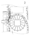
- the conveying system 1 comprises an endless conveyor belt 3 circulating between first divert wheels 2A (not shown) and second divert wheels 2B.
- the first conveyor belt 3 comprises a top run 4A and a bottom run 4B.
- the top run 4A forms a first conveying surface 5 movable between the first and second divert wheels in a first conveying direction represented by arrow P1.
- the conveying system 1 further comprises an endless second conveyor belt 7 circulating between third divert wheels 6A (not shown) and fourth divert wheels 6B (not shown).
- the second conveyor belt 7 comprises a top run 8A and a bottom run 8B.
- the top run 8A forms a second conveying surface 9, movable between the third and fourth divert wheels in a second conveying direction indicated by the arrow P2.
- the top run 8A of the second conveyor belt 7 extends at least partly above and alongside the second divert wheels 2B.
- the top run 8A of the second conveyor belt 7 extends at least partly above and along a downwardly extending quadrant aligning with the first conveying surface 5, of the second divert element formed by the second divert wheels 2B.
- the first conveyor belt 3 and the second conveyor belt 7 are in transverse mutual alignment, thereby including a gap-shaped interspace 10.
- intermediate elements T Arranged in the interspace 10 are intermediate elements T, designed as fingers 11, which bridge the gap 10 between the first conveying surface 5 and the second conveying surface 9.
- the intermediate elements T are of comb-shaped design and comprise a central carrier 31 with fingers 11.
- the central carrier 31 defines a substantially flat, closed part V of the slide-over surface, while the back parts of the fingers form a grid-shaped part R of the slide-over surface.
- the conveying system 1 further comprises a third endless conveyor belt 12, which circulates between fifth and sixth divert wheels, not shown.
- the third conveyor belt 12 runs parallel to the second conveyor belt 7, while the third conveying surface 13 formed by the top run of the third conveyor belt 12 is situated substantially in the same plane as the second conveying surface 9.
- the third conveying surface 13 moves between the fifth and the sixth divert wheels, preferably in the same direction as the second conveying surface 9, that is, in the second conveying direction indicated by arrow P2.
- the second conveyor belt 7 and the third conveyor belt 12 bound each other by their longitudinal edges 14 and 15, respectively.
- the products 16 are supplied in the first conveying direction P1 and are moved along a guide 17 from the first conveying surface 5, via the grid-shaped part R of the slide-over surface 22 formed by the back parts 26 of the fingers 11, and the closed part V of the slide-over surface 22 formed by the central carrier, onto the second conveying surface 9.
- the longitudinal edge 18 of the second conveyor belt 7 is protected, while further the falling over of products 16 is prevented.
- the length of the slide-over surface 22 between the first conveying surface 5 and the second conveying surface 9, viewed in the first conveying direction, that is, in the direction of arrow P1 has been chosen to be less than the minimum dimension of the base 23 of a product 16 to be conveyed.
- any products that remain standing on the slide-over surface 22 can be pushed on in a mechanical manner, for instance with an arm or with a vibrating device.
- the products 16 Upon arrival at the second conveying surface 9, the products 16 are moved further via the guide 17 onto the third conveying surface 13 of the third conveyor belt 12. Because the second conveyor belt 7 and the third conveyor belt 12 run in the same direction, the gap-shaped interspace 19 included between the second conveyor belt 7 and the third conveyor belt 12 can be very narrow, thus avoiding problems of damage to the longitudinal edge 15 and products falling over.
- the grid-shaped part R of the slide-over surface 22 may link up directly with the second conveying surface 9.
- the central carrier 31 or the finger 11 may then continue under the second conveying surface 9; in that case, the closed part V of the slide-over surface 22 is not present.
- the third conveyor belt 12 as such is not requisite. If desired, just a second conveyor belt 7 will suffice.
- the second conveyor belt 7 can be designed to have a large width transversely to the second conveying direction P2.
- the fingers 11 and the second conveyor belt 7 may be part of a slide-over device 20 which is placed in-between the first conveyor belt 3 and the third conveyor belt 12.
- This can provide the advantage that the first and third conveyor belts can each have their own track construction and that the slide-over device 20 is supported independently.
- the slide-over device 20 is supported on the frame 21 of the third conveyor belt 12.
- the slide-over device 20 can also be applied between a first conveyor belt 3 and a third conveyor belt 12 whose conveying directions are equally directed.
- the slide-over device 20 can be placed between the two conveyor belts, so that the second conveyor belt 7 has one extreme longitudinal edge 18 extending above and along the second chain wheels 2B of the first conveyor and has another extreme longitudinal edge 14 extending above and along the fifth chain wheels of the third conveyor belt.
- the second conveyor belt may be built up from a number of parallel conveyor belts, such as a number of chain tracks running next to each other.
- the first and the third conveyor belts can be built up from several parallel belts whose top runs in each case jointly form a conveying surface.
- the first conveyor belt 3 is designed as a modular conveying mat which is built up from a number of successive modules 23A in conveying direction P1, which have been coupled through hinge pins 24. Transversely to the conveying direction P1, the mat is built up from a number of juxtaposed rows of modules 23A which have been coupled according to a brick pattern by the hinge pins 24 extending throughout width of the mat.
- the construction of such a modular conveying mat is known to those skilled in the art, for instance from US 3,870,141 , WO 00/13993 or EP 0 903 247 .
- the second conveyor belt 7 is here likewise designed as a modular conveying mat from plastic material.
- This modular conveying mat is built up from just a single row of successive modules 23B in the second conveying direction P2, coupled by means of hinge pins (not shown).
- the longitudinal edge 15 proximal to the first conveyor belt 3 is provided with a bevel to make the gap-shaped interspace 10 between the first conveyor belt 3 and the second conveyor belt 7 as small as possible.
- Such a beveled conveying mat is known, for instance, from EP 0 722 896 . It is noted that the bevel may also be built up from separate modules which are secured to longitudinal edges of the individual modules 23.
- the third conveyor belt 12 is built up from a number of parallel tracks of modular chain.
- Each chain track is built up from a number of successive modules 23C in conveying direction P2, coupled by hinge pins.
- the hinge pins couple only the successive modules of a chain track, so that the juxtaposed tracks of the chain are not coupled.
- Such a modular chain is known to those skilled in the art and is described inter alia in EP 0 344 411 or EP 0 700 843 .
- the fingers 11 are plate-shaped and extend next to each other, upstanding, equidistantly spaced, parallel to the first conveying direction P1. Back parts 26 of the fingers 11 form a grid-shaped slide-over surface 22 at the entry 27 of the gap 10.
- the fingers 11 cooperate with grooves 28 extending in conveying direction P1 in the surface of the first conveyor belt 7.
- the fingers 11 are provided with a further back part 28 which has been formed to correspond to the bevel 29 of the longitudinal edge 18 of the second conveyor belt 7 facing the first conveying mat.
- the fingers 11 reach under the top run 8A of the second conveyor belt 7.
- the fingers support the top run 8A of the second conveyor belt 7 and form a guide 32 for the guiding projections 33 of the modules 23B of the top run 8A of the second conveyor belt 7.
- the first conveying surface 5, the second conveying surface 9 and the slide-over surface 22 are situated substantially at the same level.
- the slide-over surface 22 can be chosen to be just slightly lower than the second conveying surface 9, which in turn is situated just slightly lower than the first conveying surface 5.
- the fingers 11 are here each non-detachably connected with a central carrier 31.
- the fingers 11 are connected to the frame 21 by way of the central carrier 31, such that they are slidable transversely to the conveying direction P1 of the first conveyor belt 3, that is, in the conveying direction P2 of the second conveyor belt 7.
- the central carrier 31 is supported on a support 33 arranged on the track frame 21 of the third conveyor belt 12, but, as stated, may also be supported by an independent frame.
- the fingers can also be supported on the track frame of the first conveyor belt 3.
- the slide-over device can be supported on the track frame of the first and/or the second conveyor belt and may further be supported on a frame of its own.
- the individual fingers can be differently designed, and the interspace between the successive fingers can be different, for instance when the pattern of grooves in the first conveyor belt 3 has been chosen to be of a design with alternating interspaces or of an irregular design.
- a supporting surface formed by the intermediate elements can be designed as a slide-over plate which may or may not be provided with apertures or grooves, which is arranged in the entry of the gap-shaped interspace.
- a conveyor belt can also be manufactured in one piece.
- both the first and the second conveyor belt can circulate between more than two divert elements.
- the second conveyor belt can circulate in a rectangle, passing around four divert elements, while optionally a further divert element may be used to tension the belt.
- the dislosure includes the following.
- a conveying system comprising an endless first conveyor belt circulating between at least first and second divert elements, a top run of the first conveyor belt forming a first conveying surface movable between the divert elements in a first conveying direction, and an endless second conveyor belt circulating between at least third and fourth divert elements, a top run of the second conveyor belt forming a second conveying surface movable between the divert elements in a second conveying direction, the top run of the second conveyor belt extending at least partly above and along the second divert element, so that the first and second conveyor belts, while including a gap-shaped interspace, are in mutually transverse alignment, wherein in the interspace at least one intermediate element is arranged which bridges the gap between the first and the second conveying surface.
- a plurality of intermediate elements may be arranged, and back parts of the intermediate elements, at the entry of the gap between the first conveying surface and the second conveying surface, may form a grid-shaped part of a slide-over surface between the first and the second conveying surface.
- the intermediate elements may be designed as mutually spaced apart fingers extending in the first conveying direction. The fingers may cooperate with grooves in the surface of the first conveyor belt, extending in the first conveying direction.
- the grid-shaped part of the slide-over surface may extend from the second conveying surface into the first conveying surface.
- the longitudinal edge of the second conveyor belt that faces the first conveyor belt may be provided with a bevel.
- the at least one intermediate element may be provided with a further back part which is located lower with respect to the slide-over surface formed by the first back part and which is formed to correspond to the bevel.
- the at least one intermediate element may reach under the top run of the second conveyor belt.
- the at least one intermediate element may support the top run of the second conveyor belt.
- the intermediate elements may each comprise a plate-shaped supporting part of substantially upright orientation.
- the intermediate elements may be groupwise be connected with a central carrier.
- the intermediate elements may be provided with a breaking point.
- the intermediate elements may be arranged such that they are slidable transversely to the conveying direction of the first conveyor belt.
- the first and/or the second conveyor belt may be built up from one or more rows of successive modules in the conveying direction of the conveyor belt, which modules are pivotally coupled with the aid of hinge pins extending transversely to the conveying direction of the conveyor belt.
- a slide-over device comprising a central carrier with a number of mutually spaced-apart, substantially parallel extending fingers, back parts of the fingers forming a grid-shaped part of a slide-over surface, wherein the slide-over device is provided with an endless conveyor belt circulating between at least two divert elements, a top run of the endless conveyor belt forming a conveying surface movable between the divert elements in a conveying direction, which conveying surface is in substantially flat alignment with the slide-over surface.
- the fingers may extend substantially transversely to the conveying direction of the conveyor belt.
- the fingers may support the top run of the second conveyor belt.
- An intermediate element for a conveying system or slide-over device as above comprising at least a bar- or plate-shaped element having a first back part which during use forms a slide-over surface and a further back part which is staggered with respect to the first back part and which during use is located lower with respect to the slide-over surface and which is formed to correspond to the longitudinal edge of a conveying mat.
Landscapes
- Engineering & Computer Science (AREA)
- Mechanical Engineering (AREA)
- Structure Of Belt Conveyors (AREA)
- Chain Conveyers (AREA)
- Belt Conveyors (AREA)
- Feeding Of Articles By Means Other Than Belts Or Rollers (AREA)
- Framework For Endless Conveyors (AREA)
- Sampling And Sample Adjustment (AREA)
- Centrifugal Separators (AREA)
- Electrical Discharge Machining, Electrochemical Machining, And Combined Machining (AREA)
- Intermediate Stations On Conveyors (AREA)
Applications Claiming Priority (2)
| Application Number | Priority Date | Filing Date | Title |
|---|---|---|---|
| NL1021038A NL1021038C2 (nl) | 2002-07-09 | 2002-07-09 | Transportsysteem en overschuifinrichting. |
| EP03762929A EP1546011B1 (fr) | 2002-07-09 | 2003-07-09 | Systeme de transport equipe d'un dispositif de glissement place entre deux transporteurs a courroie et utilisation d'un element intermediaire |
Related Parent Applications (2)
| Application Number | Title | Priority Date | Filing Date |
|---|---|---|---|
| EP03762929.2 Division | 2003-07-09 | ||
| EP03762929A Division EP1546011B1 (fr) | 2002-07-09 | 2003-07-09 | Systeme de transport equipe d'un dispositif de glissement place entre deux transporteurs a courroie et utilisation d'un element intermediaire |
Publications (3)
| Publication Number | Publication Date |
|---|---|
| EP1911700A2 true EP1911700A2 (fr) | 2008-04-16 |
| EP1911700A3 EP1911700A3 (fr) | 2008-04-23 |
| EP1911700B1 EP1911700B1 (fr) | 2013-05-22 |
Family
ID=30113379
Family Applications (2)
| Application Number | Title | Priority Date | Filing Date |
|---|---|---|---|
| EP03762929A Expired - Lifetime EP1546011B1 (fr) | 2002-07-09 | 2003-07-09 | Systeme de transport equipe d'un dispositif de glissement place entre deux transporteurs a courroie et utilisation d'un element intermediaire |
| EP08150256.9A Expired - Lifetime EP1911700B1 (fr) | 2002-07-09 | 2003-07-09 | Dispositif de transfert par glissement |
Family Applications Before (1)
| Application Number | Title | Priority Date | Filing Date |
|---|---|---|---|
| EP03762929A Expired - Lifetime EP1546011B1 (fr) | 2002-07-09 | 2003-07-09 | Systeme de transport equipe d'un dispositif de glissement place entre deux transporteurs a courroie et utilisation d'un element intermediaire |
Country Status (12)
| Country | Link |
|---|---|
| US (2) | US7314130B2 (fr) |
| EP (2) | EP1546011B1 (fr) |
| AT (1) | ATE386699T1 (fr) |
| AU (1) | AU2003248160B2 (fr) |
| BR (1) | BR0305356B1 (fr) |
| CA (1) | CA2491892C (fr) |
| DE (2) | DE20380264U1 (fr) |
| DK (3) | DK1911700T3 (fr) |
| ES (1) | ES2299728T3 (fr) |
| NL (1) | NL1021038C2 (fr) |
| WO (1) | WO2004005169A1 (fr) |
| ZA (1) | ZA200500118B (fr) |
Families Citing this family (12)
| Publication number | Priority date | Publication date | Assignee | Title |
|---|---|---|---|---|
| NL1021038C2 (nl) * | 2002-07-09 | 2004-01-16 | Mcc Nederland | Transportsysteem en overschuifinrichting. |
| DE102005006203A1 (de) * | 2005-02-11 | 2006-08-24 | Khs Ag | Transporteinrichtung |
| GB0620838D0 (en) * | 2006-10-20 | 2006-11-29 | Sheppee Internat Ltd | Distributor for a train of containers |
| NL2003487C2 (nl) * | 2009-09-14 | 2011-03-15 | Rexnord Flattop Europe Bv | Transportsysteem. |
| US8157083B2 (en) | 2009-12-23 | 2012-04-17 | Laitran, L.L.C. | Self-clearing conveyor transfer system and transfer plate |
| DE102010016020A1 (de) | 2010-03-19 | 2011-09-22 | Krones Ag | Fördereinheit für ein Transportsystem für Artikel |
| NL2012375B1 (en) | 2014-03-06 | 2015-12-03 | Rexnord Flattop Europe Bv | Transfer device, conveyor system including a transfer device and method of transferring conveyed products. |
| DE102014103711A1 (de) * | 2014-03-19 | 2015-09-24 | Krones Ag | Umlenkvorrichtung für Gegenstände und Verfahren zum Umlenken von Gegenständen |
| DE102014108333B4 (de) * | 2014-06-13 | 2017-10-19 | Khs Gmbh | Transportsystem |
| NL2013917B1 (en) * | 2014-12-04 | 2016-10-11 | Rexnord Flattop Europe Bv | Conveying of plastic bottles. |
| ES2684984B1 (es) | 2017-03-31 | 2019-04-04 | Afher Eurobelt S A | Peine de transferencia y sistema de transferencia entre dos transportadores de cinta |
| CN108328213A (zh) * | 2018-04-19 | 2018-07-27 | 上海利来链条有限公司 | 一种模块化的网带链及网带系统 |
Citations (2)
| Publication number | Priority date | Publication date | Assignee | Title |
|---|---|---|---|---|
| DE8700878U1 (fr) | 1986-01-31 | 1987-03-05 | Niko Konserven-Maschinenfabrik Hinsbeck Gmbh & Co Kg, 4054 Nettetal, De | |
| EP0722896A1 (fr) | 1995-01-19 | 1996-07-24 | Rexnord Corporation | Dispositif de changement de direction pour transfert d'objets entre convoyeurs transversaux |
Family Cites Families (15)
| Publication number | Priority date | Publication date | Assignee | Title |
|---|---|---|---|---|
| US3870141A (en) | 1970-08-13 | 1975-03-11 | Laitram Corp | Modular belt |
| DE2508275A1 (de) * | 1975-02-26 | 1976-09-16 | Enzinger Union Werke Ag | Rechtwinkelige und niveaugleiche anordnung von ein- oder mehrbahnigen plattenbandfoerderern |
| DE2604705A1 (de) * | 1976-02-06 | 1977-08-11 | Alfred Gabriel Chaunier | Verbesserungen an flaschenaufgebeapparaten |
| DE3818231A1 (de) | 1988-05-28 | 1989-12-07 | Rexnord Kette Gmbh & Co Kg | Kurvengaengiger plattenbandfoerderer |
| NL9201813A (nl) * | 1992-10-19 | 1994-05-16 | Mcc Nederland | Kamvormig orgaan voor het opnemen van door een transportmat aangevoerde producten. |
| NL9401477A (nl) | 1994-09-09 | 1996-04-01 | Mcc Nederland | Ketting voor een kettingtransporteur. |
| US5850902A (en) | 1995-10-06 | 1998-12-22 | The Laitram Corporation | Transferring articles from a moving belt edge onto a normally disposed moving conveyor belt |
| US5597063A (en) * | 1995-11-06 | 1997-01-28 | The Laitram Corporation | Removal of glass articles from conveyor belts |
| NL1002390C2 (nl) | 1996-02-19 | 1997-08-20 | Mcc Nederland | Uit kunststof modules opgebouwde transportmat en modules voor een dergelijke transportmat. |
| DE19632376A1 (de) * | 1996-08-10 | 1998-02-12 | Top Foerdertechnik Gmbh | Eckstation für zwei getrennt voneinander angetriebene Transporteinrichtungen |
| JP2000516900A (ja) * | 1997-06-11 | 2000-12-19 | ザ レイトラム コーポレイション | コンベヤーベルトに対する物品移し換えアッセンブリー |
| EP0903247A1 (fr) | 1997-09-19 | 1999-03-24 | Simplex AG Bern | Procédé et dispositif pour le revêtement partiel d'une bande de papier avec une masse sensible à la pression |
| NL1008070C2 (nl) * | 1998-01-19 | 1999-07-20 | Mcc Nederland | Transportsysteem voor het transporteren van producten, alsmede overschuifinrichting. |
| NL1010040C2 (nl) | 1998-09-09 | 2000-03-10 | Mcc Nederland | Uit kunststofmodules opgebouwde transportmat en een module voor een dergelijke transportmat. |
| NL1021038C2 (nl) * | 2002-07-09 | 2004-01-16 | Mcc Nederland | Transportsysteem en overschuifinrichting. |
-
2002
- 2002-07-09 NL NL1021038A patent/NL1021038C2/nl not_active IP Right Cessation
-
2003
- 2003-07-09 EP EP03762929A patent/EP1546011B1/fr not_active Expired - Lifetime
- 2003-07-09 CA CA2491892A patent/CA2491892C/fr not_active Expired - Lifetime
- 2003-07-09 DE DE20380264U patent/DE20380264U1/de not_active Expired - Lifetime
- 2003-07-09 EP EP08150256.9A patent/EP1911700B1/fr not_active Expired - Lifetime
- 2003-07-09 DK DK08150256.9T patent/DK1911700T3/da active
- 2003-07-09 ES ES03762929T patent/ES2299728T3/es not_active Expired - Lifetime
- 2003-07-09 DE DE60319244T patent/DE60319244T2/de not_active Expired - Lifetime
- 2003-07-09 DK DK03762929T patent/DK1546011T3/da active
- 2003-07-09 AT AT03762929T patent/ATE386699T1/de not_active IP Right Cessation
- 2003-07-09 WO PCT/NL2003/000504 patent/WO2004005169A1/fr active IP Right Grant
- 2003-07-09 AU AU2003248160A patent/AU2003248160B2/en not_active Ceased
- 2003-07-09 BR BRPI0305356-3A patent/BR0305356B1/pt active IP Right Grant
- 2003-07-09 US US10/520,740 patent/US7314130B2/en not_active Expired - Lifetime
-
2004
- 2004-12-28 DK DK200400339U patent/DK200400339U3/da not_active IP Right Cessation
-
2005
- 2005-01-06 ZA ZA200500118A patent/ZA200500118B/xx unknown
-
2007
- 2007-10-25 US US11/923,797 patent/US7448490B2/en not_active Expired - Lifetime
Patent Citations (2)
| Publication number | Priority date | Publication date | Assignee | Title |
|---|---|---|---|---|
| DE8700878U1 (fr) | 1986-01-31 | 1987-03-05 | Niko Konserven-Maschinenfabrik Hinsbeck Gmbh & Co Kg, 4054 Nettetal, De | |
| EP0722896A1 (fr) | 1995-01-19 | 1996-07-24 | Rexnord Corporation | Dispositif de changement de direction pour transfert d'objets entre convoyeurs transversaux |
Also Published As
| Publication number | Publication date |
|---|---|
| EP1546011A1 (fr) | 2005-06-29 |
| DK1911700T3 (da) | 2013-07-29 |
| BR0305356A (pt) | 2004-10-05 |
| BR0305356B1 (pt) | 2012-10-16 |
| DK1546011T3 (da) | 2008-06-16 |
| ES2299728T3 (es) | 2008-06-01 |
| AU2003248160A1 (en) | 2004-01-23 |
| EP1546011B1 (fr) | 2008-02-20 |
| EP1911700B1 (fr) | 2013-05-22 |
| US20060254882A1 (en) | 2006-11-16 |
| ATE386699T1 (de) | 2008-03-15 |
| US7448490B2 (en) | 2008-11-11 |
| CA2491892C (fr) | 2011-03-22 |
| DE60319244D1 (de) | 2008-04-03 |
| EP1911700A3 (fr) | 2008-04-23 |
| AU2003248160B2 (en) | 2009-01-15 |
| DE60319244T2 (de) | 2009-02-26 |
| ZA200500118B (en) | 2006-02-22 |
| US20080047805A1 (en) | 2008-02-28 |
| DK200400339U3 (da) | 2005-02-11 |
| CA2491892A1 (fr) | 2004-01-15 |
| NL1021038C2 (nl) | 2004-01-16 |
| US7314130B2 (en) | 2008-01-01 |
| WO2004005169A1 (fr) | 2004-01-15 |
| DE20380264U1 (de) | 2005-04-21 |
Similar Documents
| Publication | Publication Date | Title |
|---|---|---|
| US7448490B2 (en) | Conveying system with a slide-over device between two belt conveyors, slide-over device and intermediate element with a slide-over surface | |
| EP3114058B1 (fr) | Dispositif de transfert, système de transporteur comprenant un dispositif de transfert et procédé de transfert de produits transportés | |
| CA2170281C (fr) | Methode de transfert pour bandes transporteuses en plastique | |
| EP0212027B1 (fr) | Procédé et dispositif pour amener et distribuer des articles | |
| NL1008070C2 (nl) | Transportsysteem voor het transporteren van producten, alsmede overschuifinrichting. | |
| KR930006601B1 (ko) | 구르기 쉽고, 연질로서 손상되기 쉬운 구상물품의 분배 및 공급방법과 장치 | |
| NL2000874C2 (nl) | Inrichting voor het transporteren van producten. | |
| EP2945888A1 (fr) | Maillon articulé | |
| KR20120108005A (ko) | 자동 제거 컨베이어 이송 시스템 및 이송 플레이트 | |
| NL1008069C2 (nl) | Transportmat alsmede systeem voor het transporteren van producten. | |
| US5383547A (en) | Scraper conveyor | |
| EP2945889B1 (fr) | Système d'avancement perpendiculaire pour tapis convoyeur de produits | |
| EP0134060B1 (fr) | Dispositif de transport pour bouteilles et similaires | |
| US9745134B1 (en) | Conveyor belt with rows of alternating types of bars | |
| NL2003487C2 (nl) | Transportsysteem. | |
| JP6301196B2 (ja) | 土砂搬送装置 | |
| GB1033065A (en) | Article reservoir and transfer system and device |
Legal Events
| Date | Code | Title | Description |
|---|---|---|---|
| PUAI | Public reference made under article 153(3) epc to a published international application that has entered the european phase |
Free format text: ORIGINAL CODE: 0009012 |
|
| PUAL | Search report despatched |
Free format text: ORIGINAL CODE: 0009013 |
|
| 17P | Request for examination filed |
Effective date: 20080115 |
|
| AC | Divisional application: reference to earlier application |
Ref document number: 1546011 Country of ref document: EP Kind code of ref document: P |
|
| AK | Designated contracting states |
Kind code of ref document: A2 Designated state(s): AT BE BG CH CY CZ DE DK EE ES FI FR GB GR HU IE IT LI LU MC NL PT RO SE SI SK TR |
|
| AK | Designated contracting states |
Kind code of ref document: A3 Designated state(s): AT BE BG CH CY CZ DE DK EE ES FI FR GB GR HU IE IT LI LU MC NL PT RO SE SI SK TR |
|
| AKX | Designation fees paid |
Designated state(s): AT BE BG CH CY CZ DE DK EE ES FI FR GB GR HU IE IT LI LU MC NL PT RO SE SI SK TR |
|
| 17Q | First examination report despatched |
Effective date: 20081210 |
|
| RTI1 | Title (correction) |
Free format text: SLIDE-OVER DEVICE |
|
| GRAP | Despatch of communication of intention to grant a patent |
Free format text: ORIGINAL CODE: EPIDOSNIGR1 |
|
| GRAS | Grant fee paid |
Free format text: ORIGINAL CODE: EPIDOSNIGR3 |
|
| GRAA | (expected) grant |
Free format text: ORIGINAL CODE: 0009210 |
|
| AC | Divisional application: reference to earlier application |
Ref document number: 1546011 Country of ref document: EP Kind code of ref document: P |
|
| AK | Designated contracting states |
Kind code of ref document: B1 Designated state(s): AT BE BG CH CY CZ DE DK EE ES FI FR GB GR HU IE IT LI LU MC NL PT RO SE SI SK TR |
|
| REG | Reference to a national code |
Ref country code: GB Ref legal event code: FG4D |
|
| REG | Reference to a national code |
Ref country code: CH Ref legal event code: EP |
|
| REG | Reference to a national code |
Ref country code: AT Ref legal event code: REF Ref document number: 613098 Country of ref document: AT Kind code of ref document: T Effective date: 20130615 |
|
| REG | Reference to a national code |
Ref country code: IE Ref legal event code: FG4D |
|
| REG | Reference to a national code |
Ref country code: DE Ref legal event code: R096 Ref document number: 60344149 Country of ref document: DE Effective date: 20130718 |
|
| REG | Reference to a national code |
Ref country code: DK Ref legal event code: T3 |
|
| REG | Reference to a national code |
Ref country code: CH Ref legal event code: NV Representative=s name: BOVARD AG, CH |
|
| REG | Reference to a national code |
Ref country code: NL Ref legal event code: T3 |
|
| REG | Reference to a national code |
Ref country code: AT Ref legal event code: MK05 Ref document number: 613098 Country of ref document: AT Kind code of ref document: T Effective date: 20130522 |
|
| PG25 | Lapsed in a contracting state [announced via postgrant information from national office to epo] |
Ref country code: FI Free format text: LAPSE BECAUSE OF FAILURE TO SUBMIT A TRANSLATION OF THE DESCRIPTION OR TO PAY THE FEE WITHIN THE PRESCRIBED TIME-LIMIT Effective date: 20130522 Ref country code: SE Free format text: LAPSE BECAUSE OF FAILURE TO SUBMIT A TRANSLATION OF THE DESCRIPTION OR TO PAY THE FEE WITHIN THE PRESCRIBED TIME-LIMIT Effective date: 20130522 Ref country code: SI Free format text: LAPSE BECAUSE OF FAILURE TO SUBMIT A TRANSLATION OF THE DESCRIPTION OR TO PAY THE FEE WITHIN THE PRESCRIBED TIME-LIMIT Effective date: 20130522 Ref country code: PT Free format text: LAPSE BECAUSE OF FAILURE TO SUBMIT A TRANSLATION OF THE DESCRIPTION OR TO PAY THE FEE WITHIN THE PRESCRIBED TIME-LIMIT Effective date: 20130923 Ref country code: GR Free format text: LAPSE BECAUSE OF FAILURE TO SUBMIT A TRANSLATION OF THE DESCRIPTION OR TO PAY THE FEE WITHIN THE PRESCRIBED TIME-LIMIT Effective date: 20130823 Ref country code: AT Free format text: LAPSE BECAUSE OF FAILURE TO SUBMIT A TRANSLATION OF THE DESCRIPTION OR TO PAY THE FEE WITHIN THE PRESCRIBED TIME-LIMIT Effective date: 20130522 Ref country code: ES Free format text: LAPSE BECAUSE OF FAILURE TO SUBMIT A TRANSLATION OF THE DESCRIPTION OR TO PAY THE FEE WITHIN THE PRESCRIBED TIME-LIMIT Effective date: 20130902 |
|
| PG25 | Lapsed in a contracting state [announced via postgrant information from national office to epo] |
Ref country code: BG Free format text: LAPSE BECAUSE OF FAILURE TO SUBMIT A TRANSLATION OF THE DESCRIPTION OR TO PAY THE FEE WITHIN THE PRESCRIBED TIME-LIMIT Effective date: 20130822 |
|
| PG25 | Lapsed in a contracting state [announced via postgrant information from national office to epo] |
Ref country code: CZ Free format text: LAPSE BECAUSE OF FAILURE TO SUBMIT A TRANSLATION OF THE DESCRIPTION OR TO PAY THE FEE WITHIN THE PRESCRIBED TIME-LIMIT Effective date: 20130522 Ref country code: BE Free format text: LAPSE BECAUSE OF FAILURE TO SUBMIT A TRANSLATION OF THE DESCRIPTION OR TO PAY THE FEE WITHIN THE PRESCRIBED TIME-LIMIT Effective date: 20130522 Ref country code: SK Free format text: LAPSE BECAUSE OF FAILURE TO SUBMIT A TRANSLATION OF THE DESCRIPTION OR TO PAY THE FEE WITHIN THE PRESCRIBED TIME-LIMIT Effective date: 20130522 Ref country code: EE Free format text: LAPSE BECAUSE OF FAILURE TO SUBMIT A TRANSLATION OF THE DESCRIPTION OR TO PAY THE FEE WITHIN THE PRESCRIBED TIME-LIMIT Effective date: 20130522 |
|
| PG25 | Lapsed in a contracting state [announced via postgrant information from national office to epo] |
Ref country code: RO Free format text: LAPSE BECAUSE OF FAILURE TO SUBMIT A TRANSLATION OF THE DESCRIPTION OR TO PAY THE FEE WITHIN THE PRESCRIBED TIME-LIMIT Effective date: 20130522 Ref country code: MC Free format text: LAPSE BECAUSE OF FAILURE TO SUBMIT A TRANSLATION OF THE DESCRIPTION OR TO PAY THE FEE WITHIN THE PRESCRIBED TIME-LIMIT Effective date: 20130522 Ref country code: IT Free format text: LAPSE BECAUSE OF FAILURE TO SUBMIT A TRANSLATION OF THE DESCRIPTION OR TO PAY THE FEE WITHIN THE PRESCRIBED TIME-LIMIT Effective date: 20130522 |
|
| PLBE | No opposition filed within time limit |
Free format text: ORIGINAL CODE: 0009261 |
|
| STAA | Information on the status of an ep patent application or granted ep patent |
Free format text: STATUS: NO OPPOSITION FILED WITHIN TIME LIMIT |
|
| GBPC | Gb: european patent ceased through non-payment of renewal fee |
Effective date: 20130822 |
|
| REG | Reference to a national code |
Ref country code: IE Ref legal event code: MM4A |
|
| 26N | No opposition filed |
Effective date: 20140225 |
|
| REG | Reference to a national code |
Ref country code: DE Ref legal event code: R097 Ref document number: 60344149 Country of ref document: DE Effective date: 20140225 |
|
| PG25 | Lapsed in a contracting state [announced via postgrant information from national office to epo] |
Ref country code: IE Free format text: LAPSE BECAUSE OF NON-PAYMENT OF DUE FEES Effective date: 20130709 Ref country code: GB Free format text: LAPSE BECAUSE OF NON-PAYMENT OF DUE FEES Effective date: 20130822 |
|
| REG | Reference to a national code |
Ref country code: FR Ref legal event code: PLFP Year of fee payment: 13 |
|
| PG25 | Lapsed in a contracting state [announced via postgrant information from national office to epo] |
Ref country code: CY Free format text: LAPSE BECAUSE OF FAILURE TO SUBMIT A TRANSLATION OF THE DESCRIPTION OR TO PAY THE FEE WITHIN THE PRESCRIBED TIME-LIMIT Effective date: 20130522 Ref country code: TR Free format text: LAPSE BECAUSE OF FAILURE TO SUBMIT A TRANSLATION OF THE DESCRIPTION OR TO PAY THE FEE WITHIN THE PRESCRIBED TIME-LIMIT Effective date: 20130522 |
|
| PG25 | Lapsed in a contracting state [announced via postgrant information from national office to epo] |
Ref country code: HU Free format text: LAPSE BECAUSE OF FAILURE TO SUBMIT A TRANSLATION OF THE DESCRIPTION OR TO PAY THE FEE WITHIN THE PRESCRIBED TIME-LIMIT; INVALID AB INITIO Effective date: 20030709 Ref country code: LU Free format text: LAPSE BECAUSE OF NON-PAYMENT OF DUE FEES Effective date: 20130709 |
|
| REG | Reference to a national code |
Ref country code: FR Ref legal event code: PLFP Year of fee payment: 14 |
|
| REG | Reference to a national code |
Ref country code: FR Ref legal event code: PLFP Year of fee payment: 15 |
|
| PGFP | Annual fee paid to national office [announced via postgrant information from national office to epo] |
Ref country code: GR Payment date: 20170926 Year of fee payment: 15 |
|
| REG | Reference to a national code |
Ref country code: FR Ref legal event code: PLFP Year of fee payment: 16 |
|
| REG | Reference to a national code |
Ref country code: CH Ref legal event code: PL |
|
| PG25 | Lapsed in a contracting state [announced via postgrant information from national office to epo] |
Ref country code: CH Free format text: LAPSE BECAUSE OF NON-PAYMENT OF DUE FEES Effective date: 20180731 Ref country code: LI Free format text: LAPSE BECAUSE OF NON-PAYMENT OF DUE FEES Effective date: 20180731 |
|
| PGFP | Annual fee paid to national office [announced via postgrant information from national office to epo] |
Ref country code: NL Payment date: 20220621 Year of fee payment: 20 |
|
| PGFP | Annual fee paid to national office [announced via postgrant information from national office to epo] |
Ref country code: DK Payment date: 20220725 Year of fee payment: 20 Ref country code: DE Payment date: 20220720 Year of fee payment: 20 |
|
| PGFP | Annual fee paid to national office [announced via postgrant information from national office to epo] |
Ref country code: FR Payment date: 20220720 Year of fee payment: 20 |
|
| P01 | Opt-out of the competence of the unified patent court (upc) registered |
Effective date: 20230522 |
|
| REG | Reference to a national code |
Ref country code: DE Ref legal event code: R071 Ref document number: 60344149 Country of ref document: DE |
|
| REG | Reference to a national code |
Ref country code: DK Ref legal event code: EUP Expiry date: 20230709 |
|
| REG | Reference to a national code |
Ref country code: NL Ref legal event code: MK Effective date: 20230708 |