EP1908496A1 - Système de détection de position - Google Patents
Système de détection de position Download PDFInfo
- Publication number
- EP1908496A1 EP1908496A1 EP06780988A EP06780988A EP1908496A1 EP 1908496 A1 EP1908496 A1 EP 1908496A1 EP 06780988 A EP06780988 A EP 06780988A EP 06780988 A EP06780988 A EP 06780988A EP 1908496 A1 EP1908496 A1 EP 1908496A1
- Authority
- EP
- European Patent Office
- Prior art keywords
- infrared
- screen
- unit
- detected
- reflected light
- Prior art date
- Legal status (The legal status is an assumption and is not a legal conclusion. Google has not performed a legal analysis and makes no representation as to the accuracy of the status listed.)
- Withdrawn
Links
Images


Classifications
-
- A—HUMAN NECESSITIES
- A63—SPORTS; GAMES; AMUSEMENTS
- A63F—CARD, BOARD, OR ROULETTE GAMES; INDOOR GAMES USING SMALL MOVING PLAYING BODIES; VIDEO GAMES; GAMES NOT OTHERWISE PROVIDED FOR
- A63F13/00—Video games, i.e. games using an electronically generated display having two or more dimensions
- A63F13/20—Input arrangements for video game devices
- A63F13/21—Input arrangements for video game devices characterised by their sensors, purposes or types
- A63F13/213—Input arrangements for video game devices characterised by their sensors, purposes or types comprising photodetecting means, e.g. cameras, photodiodes or infrared cells
-
- A—HUMAN NECESSITIES
- A63—SPORTS; GAMES; AMUSEMENTS
- A63B—APPARATUS FOR PHYSICAL TRAINING, GYMNASTICS, SWIMMING, CLIMBING, OR FENCING; BALL GAMES; TRAINING EQUIPMENT
- A63B24/00—Electric or electronic controls for exercising apparatus of preceding groups; Controlling or monitoring of exercises, sportive games, training or athletic performances
- A63B24/0003—Analysing the course of a movement or motion sequences during an exercise or trainings sequence, e.g. swing for golf or tennis
-
- A—HUMAN NECESSITIES
- A63—SPORTS; GAMES; AMUSEMENTS
- A63B—APPARATUS FOR PHYSICAL TRAINING, GYMNASTICS, SWIMMING, CLIMBING, OR FENCING; BALL GAMES; TRAINING EQUIPMENT
- A63B63/00—Targets or goals for ball games
-
- A63F13/04—
-
- A—HUMAN NECESSITIES
- A63—SPORTS; GAMES; AMUSEMENTS
- A63F—CARD, BOARD, OR ROULETTE GAMES; INDOOR GAMES USING SMALL MOVING PLAYING BODIES; VIDEO GAMES; GAMES NOT OTHERWISE PROVIDED FOR
- A63F13/00—Video games, i.e. games using an electronically generated display having two or more dimensions
- A63F13/20—Input arrangements for video game devices
- A63F13/21—Input arrangements for video game devices characterised by their sensors, purposes or types
- A63F13/216—Input arrangements for video game devices characterised by their sensors, purposes or types using geographical information, e.g. location of the game device or player using GPS
-
- A—HUMAN NECESSITIES
- A63—SPORTS; GAMES; AMUSEMENTS
- A63F—CARD, BOARD, OR ROULETTE GAMES; INDOOR GAMES USING SMALL MOVING PLAYING BODIES; VIDEO GAMES; GAMES NOT OTHERWISE PROVIDED FOR
- A63F9/00—Games not otherwise provided for
- A63F9/02—Shooting or hurling games
-
- F—MECHANICAL ENGINEERING; LIGHTING; HEATING; WEAPONS; BLASTING
- F41—WEAPONS
- F41J—TARGETS; TARGET RANGES; BULLET CATCHERS
- F41J5/00—Target indicating systems; Target-hit or score detecting systems
- F41J5/08—Infrared hit-indicating systems
-
- G—PHYSICS
- G06—COMPUTING OR CALCULATING; COUNTING
- G06F—ELECTRIC DIGITAL DATA PROCESSING
- G06F3/00—Input arrangements for transferring data to be processed into a form capable of being handled by the computer; Output arrangements for transferring data from processing unit to output unit, e.g. interface arrangements
- G06F3/01—Input arrangements or combined input and output arrangements for interaction between user and computer
- G06F3/03—Arrangements for converting the position or the displacement of a member into a coded form
- G06F3/0304—Detection arrangements using opto-electronic means
- G06F3/0308—Detection arrangements using opto-electronic means comprising a plurality of distinctive and separately oriented light emitters or reflectors associated to the pointing device, e.g. remote cursor controller with distinct and separately oriented LEDs at the tip whose radiations are captured by a photo-detector associated to the screen
-
- G—PHYSICS
- G06—COMPUTING OR CALCULATING; COUNTING
- G06F—ELECTRIC DIGITAL DATA PROCESSING
- G06F3/00—Input arrangements for transferring data to be processed into a form capable of being handled by the computer; Output arrangements for transferring data from processing unit to output unit, e.g. interface arrangements
- G06F3/01—Input arrangements or combined input and output arrangements for interaction between user and computer
- G06F3/03—Arrangements for converting the position or the displacement of a member into a coded form
- G06F3/041—Digitisers, e.g. for touch screens or touch pads, characterised by the transducing means
- G06F3/042—Digitisers, e.g. for touch screens or touch pads, characterised by the transducing means by opto-electronic means
- G06F3/0421—Digitisers, e.g. for touch screens or touch pads, characterised by the transducing means by opto-electronic means by interrupting or reflecting a light beam, e.g. optical touch-screen
-
- G—PHYSICS
- G06—COMPUTING OR CALCULATING; COUNTING
- G06F—ELECTRIC DIGITAL DATA PROCESSING
- G06F3/00—Input arrangements for transferring data to be processed into a form capable of being handled by the computer; Output arrangements for transferring data from processing unit to output unit, e.g. interface arrangements
- G06F3/01—Input arrangements or combined input and output arrangements for interaction between user and computer
- G06F3/03—Arrangements for converting the position or the displacement of a member into a coded form
- G06F3/041—Digitisers, e.g. for touch screens or touch pads, characterised by the transducing means
- G06F3/042—Digitisers, e.g. for touch screens or touch pads, characterised by the transducing means by opto-electronic means
- G06F3/0425—Digitisers, e.g. for touch screens or touch pads, characterised by the transducing means by opto-electronic means using a single imaging device like a video camera for tracking the absolute position of a single or a plurality of objects with respect to an imaged reference surface, e.g. video camera imaging a display or a projection screen, a table or a wall surface, on which a computer generated image is displayed or projected
-
- A—HUMAN NECESSITIES
- A63—SPORTS; GAMES; AMUSEMENTS
- A63B—APPARATUS FOR PHYSICAL TRAINING, GYMNASTICS, SWIMMING, CLIMBING, OR FENCING; BALL GAMES; TRAINING EQUIPMENT
- A63B24/00—Electric or electronic controls for exercising apparatus of preceding groups; Controlling or monitoring of exercises, sportive games, training or athletic performances
- A63B24/0021—Tracking a path or terminating locations
- A63B2024/0037—Tracking a path or terminating locations on a target surface or at impact on the ground
- A63B2024/0043—Systems for locating the point of impact on a specific surface
-
- A—HUMAN NECESSITIES
- A63—SPORTS; GAMES; AMUSEMENTS
- A63B—APPARATUS FOR PHYSICAL TRAINING, GYMNASTICS, SWIMMING, CLIMBING, OR FENCING; BALL GAMES; TRAINING EQUIPMENT
- A63B2220/00—Measuring of physical parameters relating to sporting activity
- A63B2220/05—Image processing for measuring physical parameters
-
- A—HUMAN NECESSITIES
- A63—SPORTS; GAMES; AMUSEMENTS
- A63B—APPARATUS FOR PHYSICAL TRAINING, GYMNASTICS, SWIMMING, CLIMBING, OR FENCING; BALL GAMES; TRAINING EQUIPMENT
- A63B2220/00—Measuring of physical parameters relating to sporting activity
- A63B2220/80—Special sensors, transducers or devices therefor
- A63B2220/806—Video cameras
-
- A—HUMAN NECESSITIES
- A63—SPORTS; GAMES; AMUSEMENTS
- A63F—CARD, BOARD, OR ROULETTE GAMES; INDOOR GAMES USING SMALL MOVING PLAYING BODIES; VIDEO GAMES; GAMES NOT OTHERWISE PROVIDED FOR
- A63F13/00—Video games, i.e. games using an electronically generated display having two or more dimensions
- A63F13/50—Controlling the output signals based on the game progress
- A63F13/52—Controlling the output signals based on the game progress involving aspects of the displayed game scene
-
- A—HUMAN NECESSITIES
- A63—SPORTS; GAMES; AMUSEMENTS
- A63F—CARD, BOARD, OR ROULETTE GAMES; INDOOR GAMES USING SMALL MOVING PLAYING BODIES; VIDEO GAMES; GAMES NOT OTHERWISE PROVIDED FOR
- A63F2300/00—Features of games using an electronically generated display having two or more dimensions, e.g. on a television screen, showing representations related to the game
- A63F2300/10—Features of games using an electronically generated display having two or more dimensions, e.g. on a television screen, showing representations related to the game characterized by input arrangements for converting player-generated signals into game device control signals
- A63F2300/1043—Features of games using an electronically generated display having two or more dimensions, e.g. on a television screen, showing representations related to the game characterized by input arrangements for converting player-generated signals into game device control signals being characterized by constructional details
-
- A—HUMAN NECESSITIES
- A63—SPORTS; GAMES; AMUSEMENTS
- A63F—CARD, BOARD, OR ROULETTE GAMES; INDOOR GAMES USING SMALL MOVING PLAYING BODIES; VIDEO GAMES; GAMES NOT OTHERWISE PROVIDED FOR
- A63F2300/00—Features of games using an electronically generated display having two or more dimensions, e.g. on a television screen, showing representations related to the game
- A63F2300/10—Features of games using an electronically generated display having two or more dimensions, e.g. on a television screen, showing representations related to the game characterized by input arrangements for converting player-generated signals into game device control signals
- A63F2300/1068—Features of games using an electronically generated display having two or more dimensions, e.g. on a television screen, showing representations related to the game characterized by input arrangements for converting player-generated signals into game device control signals being specially adapted to detect the point of contact of the player on a surface, e.g. floor mat, touch pad
-
- A—HUMAN NECESSITIES
- A63—SPORTS; GAMES; AMUSEMENTS
- A63F—CARD, BOARD, OR ROULETTE GAMES; INDOOR GAMES USING SMALL MOVING PLAYING BODIES; VIDEO GAMES; GAMES NOT OTHERWISE PROVIDED FOR
- A63F2300/00—Features of games using an electronically generated display having two or more dimensions, e.g. on a television screen, showing representations related to the game
- A63F2300/10—Features of games using an electronically generated display having two or more dimensions, e.g. on a television screen, showing representations related to the game characterized by input arrangements for converting player-generated signals into game device control signals
- A63F2300/1087—Features of games using an electronically generated display having two or more dimensions, e.g. on a television screen, showing representations related to the game characterized by input arrangements for converting player-generated signals into game device control signals comprising photodetecting means, e.g. a camera
-
- A—HUMAN NECESSITIES
- A63—SPORTS; GAMES; AMUSEMENTS
- A63F—CARD, BOARD, OR ROULETTE GAMES; INDOOR GAMES USING SMALL MOVING PLAYING BODIES; VIDEO GAMES; GAMES NOT OTHERWISE PROVIDED FOR
- A63F2300/00—Features of games using an electronically generated display having two or more dimensions, e.g. on a television screen, showing representations related to the game
- A63F2300/80—Features of games using an electronically generated display having two or more dimensions, e.g. on a television screen, showing representations related to the game specially adapted for executing a specific type of game
- A63F2300/8023—Features of games using an electronically generated display having two or more dimensions, e.g. on a television screen, showing representations related to the game specially adapted for executing a specific type of game the game being played by multiple players at a common site, e.g. in an arena, theatre, shopping mall using a large public display
-
- A—HUMAN NECESSITIES
- A63—SPORTS; GAMES; AMUSEMENTS
- A63F—CARD, BOARD, OR ROULETTE GAMES; INDOOR GAMES USING SMALL MOVING PLAYING BODIES; VIDEO GAMES; GAMES NOT OTHERWISE PROVIDED FOR
- A63F2300/00—Features of games using an electronically generated display having two or more dimensions, e.g. on a television screen, showing representations related to the game
- A63F2300/80—Features of games using an electronically generated display having two or more dimensions, e.g. on a television screen, showing representations related to the game specially adapted for executing a specific type of game
- A63F2300/8029—Fighting without shooting
-
- A—HUMAN NECESSITIES
- A63—SPORTS; GAMES; AMUSEMENTS
- A63F—CARD, BOARD, OR ROULETTE GAMES; INDOOR GAMES USING SMALL MOVING PLAYING BODIES; VIDEO GAMES; GAMES NOT OTHERWISE PROVIDED FOR
- A63F9/00—Games not otherwise provided for
- A63F9/02—Shooting or hurling games
- A63F9/0291—Shooting or hurling games with a simulated projectile, e.g. an image on a screen
Definitions
- the present invention relates to a system for detecting a position of an object. More specifically, the present invention relates to a system for detecting a position of an object on a given plane in a space.
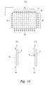
- Fig. 10 is an explanatory diagram showing a configuration for detecting a position of a ball in such a game.
- Fig. 10A shows that infrared rays irradiation means Lx and Ly are arranged along the periphery of a display D, which form a net of infrared rays in a grid. Facing the infrared rays irradiation means Lx and Ly are infrared sensors Sx and Sy which are arranged along the periphery of the display D.
- Fig. 10B shows that the infrared rays irradiation means Lx and Ly and the infrared sensors Sx and Sy are arranged very close to the display D.
- the infrared sensors Sx and Sy detect that the infrared rays have been blocked.
- a position at which the ball hit is specified by an X-Y coordinate by determining which infrared sensors Sx and Sy have detected the block of the infrared rays.
- the detection accuracy depends on the gaps between the infrared rays irradiation means Lx and Ly, and the infrared sensors Sx and Sy that are arranged in the x direction and y direction as shown in the figure. For this reason, the increased number of infrared rays irradiation means Lx and Ly, and infrared sensors Sx and Sy are needed should the detection accuracy be improved. Furthermore, because it is necessary to set the infrared rays irradiation means Lx and Ly, and the infrared sensors Sx and Sy such that they face each other accurately, the setting will be more difficult as they increase in number.
- one ball may be detected by a plurality of infrared sensors in the x direction and/or y direction. In this case, one ball may possibly be recognized as a plurality of balls in error.
- An object of the present invention is to accurately detect a position of an object on a given plane in a space irrespective of the number of objects.
- a first aspect of the present invention provides a position detection system comprising the following units.
- a position of reflected light is specified by selectively detecting only the reflected light on the infrared screen. Even when a plurality of objects to be detected simultaneously pass through the infrared screen, a position on the infrared screen at which each object to be detected has passed through can be accurately specified without a need of providing a high-precision sensor.
- the position detection system may further comprise a real screen provided near and along the infrared screen, and opposite the reflected light detection unit with the infrared screen therebetween.
- the real screen is set opposite the reflected light detection means with the infrared screen therebetween. Note that the position detection becomes possible for the whole real screen when the size of infrared screen is big enough to cover the real screen.
- a distance between the infrared screen and the real screen is preferably adjusted such that the distance does not exceed a maximum length of the object to be detected.
- the distance between the infrared screen and the real screen preferably does not exceed the maximum length of the object to be detected.
- the object to be detected is a ball.
- the infrared screen generation unit is preferably arranged at least on a part of a periphery of a given rectangular-shaped plane in a space, and includes a plurality of infrared rays irradiation unit for irradiating the infrared rays having a light axis on the plane.
- Each infrared rays irradiation means irradiates the infrared rays having a light axis on the rectangular plane. In other words, an irradiation direction of the infrared rays is included in the rectangular plane.
- a planar net of infrared rays, i.e. the infrared screen can be formed.
- the thickness of the infrared screen can be minimized by irradiating the infrared rays having directivity. The less the thickness of the infrared screen is, the less the distance between the infrared screen and the real screen becomes, thus enabling the position detection near the real screen.
- the emitting time of reflected light can be made shorter, even when a plurality of objects to be detected pass through the infrared screen simultaneously, a gap between a position at which each object to be detected hits on the real screen and the timing that it hits thereon can be made smaller.
- the plurality of infrared rays irradiation unit are preferably arranged along at least two sides of four sides that form the rectangular-shaped plane.
- the infrared rays irradiation means may be arranged along two sides that face each other, or along two sides that are perpendicular to each other. With this configuration, a rectangular-shaped infrared screen can be formed.
- the infrared rays are irradiated on an object to be detected that passes through the infrared screen at least from two directions. Therefore, even when a plurality of objects to be detected pass through the screen simultaneously, it is less likely that one object to be detected creates a shadow for another object to be detected, thus the infrared rays can be irradiated evenly on all the plurality of objects to be detected.
- the position detection system may further comprise a game execution unit for executing a given game. It is preferable that the real screen is connected to the game execution unit and is a display for outputting an image from the game execution unit. In this system, the real screen is connected to the game execution means, and is a display for outputting an image from the computer terminal.
- the position detection system of Invention 1 may be applied to a game.
- the computer terminal performs the collision detection of a virtual object in a game space displayed on the display with a ball a player throws at the display.
- the position detection system of Invention 1 may be used for determining a contact position of the ball on the display, which is necessary for the collision detection. Furthermore, even in a case where a plurality of balls hit the display simultaneously, the collision detection of each ball with a virtual object can be performed individually. Thus, the accuracy of the collision detection in a game improves and it can be expected that the game becomes more enjoyable.
- the reflected light detection unit preferably includes a first imaging unit and an infrared filter.
- the first imaging unit repeatedly images at a predetermined time interval, and is set such that at least the whole real screen comes within its angle of view.
- the infrared filter selects light inputted into the first imaging unit, and is attached to the first imaging unit.
- the position specifying unit preferably specifies the reflection position of the infrared rays on the infrared screen caused by the object to be detected by analyzing each image imaged by the first imaging unit.
- the position specifying means specifies a reflection position of the infrared rays on the infrared screen caused by the object to be detected by analyzing each image imaged by the first imaging means.
- an emitting position on the infrared screen can be detected at a predetermined time interval.
- a CCD camera and video camera and the like may be used as the first imaging means.
- the first imaging means has a means to correct a distortion of an image which has been imaged.
- a distortion correction lens such as an aspheric lens may be used.
- the number of the first imaging means is not necessarily one. For example, when a real screen is big, a plurality of first imaging means may be provided so that the whole real screen comes within the total angle of view of the plurality of first imaging means.
- the position detection system may further comprise a second imaging unit and a color specifying unit.
- the second imaging unit repeatedly images at a predetermined time interval, and is set such that at least the whole real screen comes within its angle of view.
- the color specifying unit specifies a color of the object to be detected by analyzing each image imaged by the first imaging unit and the second imaging unit.
- the color of the object to be detected can be specified by imaging a color image by inputting visible light into the second imaging means and analyzing the color at a position specified based on the image of the first imaging means. For example, in a case where the color of an object to be detected is different for each player in a game played by a plurality of players, it becomes possible to perform the collision detection for each player.
- the number of the second imaging means is not necessarily one. For example, when a real screen is big, a plurality of second imaging means may be provided so that the whole real screen comes within the total angle of view of the plurality of second imaging means.
- the position detection system may further comprise a timing detection unit for detecting timing that reflected light detected by the reflected light detection unit is caused.
- Another aspect of the present invention provides a position detection method comprising the following steps.
- This method is executed in the position detection system in the first aspect of the present invention and demonstrates the same effects as the first aspect of the invention.
- a position of reflected light of an object passing through an infrared screen is specified by analyzing an image obtained by selectively imaging the infrared light.
- the infrared screen is formed in front of a real screen, for example, a display, reflected light is only caused just in front of the display.
- the infrared light is selectively imaged, an image displayed with visible light and reflected light in the infrared region are separated, thereby only reflected light can be imaged.
- Location of the imaged reflected light on the display can be specified by a publicly known image analysis technique.
- This method can be applied to a game machine.
- a game machine that executes a given game and a display are connected, and an image from the game machine is outputted to the display.
- the game machine performs the collision detection, for example, of a virtual object in a game space displayed on the display with a ball that a player throws at the display.
- the aforementioned method may be employed for detecting a contact position of the ball on the display. Even when a plurality of balls hit the display, the collision detection of each ball with a virtual object can be performed individually. Thus, the accuracy of the collision detection in the game improves and it can be expected that the game becomes more enjoyable.
- Fig. 1 is an external configuration view of a position detection system according to a first embodiment.
- the position detection system includes a game case 10, an infrared ray camera 20 provided at the upper front of the game case 10 (corresponding to a part of a reflected light detection means) and a color camera 21.
- the infrared camera 20 and the color camera 21 are collectively described as cameras 20 and 21.
- the game case 10 has the following elements.
- the infrared camera 20 is set such that at least the whole display 11 comes within its angle of view and inputs images, which are continuously imaged or repeatedly imaged at a predetermined time interval ⁇ T1, into the image analysis board 13.
- the time interval ⁇ T1 may be more than a time interval ⁇ T2 at which an image of the display 11 is updated ( ⁇ T1 ⁇ ⁇ T2).
- the infrared camera 20 includes a camera (corresponding to a first imaging means) and an infrared filter (not shown) attached to the camera.
- light in the infrared region is selectively inputted to the infrared camera 20.
- the infrared camera 20 selectively images the reflected light by the ball that has passed through the infrared screen.
- a camera that only detects the infrared light may be used as the infrared camera 20 instead of using the infrared filter.
- a CCD camera, video camera, digital camera, etc. may be used as a camera that makes up the infrared camera 20.
- a means to correct a distortion of an image, that has been imaged is provided.
- a distortion correction lens such as an aspheric lens may be used.
- the color camera 21 (corresponding to a second imaging means) is set such that at least the whole display 11 comes within its angle of view and inputs images, that are continuously imaged or repeatedly imaged at a predetermined time interval ⁇ T1, into the image analysis board 13.
- the timing of the imaging is preferably synchronized with that of the infrared camera 20.
- the aforementioned various cameras may be used as the color camera 21.
- a filter for blocking out light in the infrared region for example, a filter for selectively allowing light in the visible light region to pass through, may be attached to the aforementioned camera, and use it as the color camera 21.
- the color camera 21 with such a filter attached thereto can selectively image an image displayed on the display 11.
- the color of a ball can be determined by analyzing the color at the position that is specified based on the image from the infrared camera 20. For example, when the color of a ball is different for each player in a game played by a plurality of players, it is possible to perform the collision detection for each player.
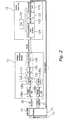
- Fig. 2 is an explanatory diagram showing hardware configuration of the image analysis board 13 and the game machine 12 shown in Fig. 1 .
- the infrared camera 20 is indicated as IR camera.
- the image analysis board 13 has a CPU 131, a ROM 132, a RAM 133, a communication port 134, two frame buffers 135a, b and two image processing units 136a, b.
- the image processing units 136a, b convert pictures inputted from the camera 20 and 21 into digital data and develop the data in the frame buffers 135a, b. More specifically, the image processing units 136a, b (1) perform A/D conversion of an inputted picture, (2) generate an address and write the data that was converted into digital data in a memory space that is to be stored in the frame buffers 134a, b, and (3) notify the CPU 131 of the completion of the aforementioned processes (1) and (2) for one frame. An image imaged by the infrared camera 20 is developed in the frame buffer 135a. An image imaged by the color camera 21 is developed in the frame buffer 135b.
- the CPU 131 reads out an image processing program stored in the ROM 132 and specifies a position of reflected light of a ball based on the image written into the frame buffer 135a while using the RAM 133 as a working area.
- the CPU 131 specifies color information at the position of reflected light based on the image written into the frame buffer 135b. An image analysis process carried out by the CPU 131 will be explained more in detail later.
- the CPU 131 writes the specified position information and color information into a buffer 124 of the game machine 12 via the communication port 134.
- the game machine 12 has the following elements (a) to (e).
- the game machine 12 is connected to a speaker, an audio reproducing unit, an input operation unit and a coin accepting unit (not shown).
- the speaker outputs sounds while a game is being executed or a demonstration screen is being displayed.
- the audio reproducing unit generates sound data for the speaker to output.
- the input operation unit is comprised of a joy stick, operation buttons and the like, and accepts an instruction input from a player.
- the coin accepting unit accepts a credit by an inserted coin.
- the game machine 12 thus configured executes a game in accordance with the control program stored in the ROM 123.
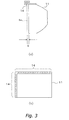
- Fig. 3A is an explanatory diagram showing a positional relationship between the infrared screen and the display 11.
- An infrared screen S IR is positioned between the display side of the display 11 and the infrared camera 20.
- the display 11 is set opposite the infrared camera 20 with the infrared screen S IR therebetween.
- the infrared screen S IR and the display side of the display 11 are preferably positioned close to each other. By positioning the infrared screen S IR and the display side of the display 11 close to each other, it becomes possible to specify where an object has hit on the display side of the display without a noticeable gap. More specifically, by forming the infrared screen S IR just in front of the display side of the display 11, reflection of the infrared rays by the ball is caused just in front of the display. The closer the infrared screen S IR and the display side of the display 11 are, the smaller the difference between the position on the display 11 at which the ball hits and the position of reflection becomes.
- a distance G between the infrared screen S IR and the display side of the display 11 is adjusted so as not to exceed the maximum length of the ball, i.e. the diameter of the ball.
- the infrared screen S IR is preferably the same size as or bigger than the display side of the display 11 and covers the display side. It is because the size of the infrared screen S IR determines an area that can detect the position of the ball. Conversely, another configuration is also possible where the infrared screen S IR is smaller than the display side of the display 11. In this configuration, it is detected that the ball is thrown outside the display 11, and the detection result can be reflected in a game. For example, a penalty such as point reduction may be given to a player if the ball is thrown outside the display 11.
- Fig. 3B shows an arrangement example of a plurality of infrared lamps 14.
- the plurality of infrared lamps 14 are arranged at least on a part of the periphery of a given rectangular-shaped plane within a space.
- the plurality of infrared lamps 14 are evenly spaced and arranged along the periphery of the rectangular-shaped plane of the display side of the display.
- the plurality of infrared lamps 14 irradiate the infrared rays with directivity in the direction along the display side of the display. More specifically, the light axis of the infrared rays irradiated from the infrared lamp 14 is positioned on the rectangular-shaped plane, and the irradiation direction of the infrared rays is included in the rectangular-shaped plane.
- the thickness of the infrared screen will be smaller. This enables the gap between the position of reflection caused by the ball passing through the infrared screen and the position on the display that the ball actually hits to be made smaller.
- the accuracy of the position detection of the ball will be improved. Furthermore, because the emitting time of reflected light can be made shorter, the gap between the timing that the ball hits the infrared screen and the timing that reflected light is emitted can also be made smaller.
- the plurality of infrared lamps 14 are preferably arranged at least along two sides. They may be arranged along two sides that face each other, or along two sides that are perpendicular to each other.
- the plurality of infrared lamps 14 form the rectangular-shaped infrared screen.
- the infrared rays are evenly irradiated on the ball passing through this infrared screen at least from two directions. Therefore, even when a plurality of balls pass through the screen simultaneously, it is less likely that one ball creates shadow for another ball, thus the infrared rays can be irradiated evenly on all the plurality of balls.
- the interval between the infrared lamps 14 does not necessarily have to be regular, but the intensity of the infrared rays in the infrared screen will be uniform by making the intervals regular.
- Figs. 4 , 5 and 6 each shows a screen example showing one example of a game executed by the game machine 12.
- a player throws a ball at a meteorite that is falling from the sky and destroys it so that it does not hit a building in which a rabbit lives.
- the remaining lives of the rabbit are indicated in number at a position corresponding to each rabbit in the upper part of the screen. Every time the rabbit is damaged by the meteorite, the remaining lives of the rabbit are reduced. When the meteorite hits the rabbit, the game is over even when the remaining lives are not zero (see Fig. 5 ).
- up to four players can participate in the game to save the rabbits.
- a gigantic meteorite is falling from above in the final phase of the game, and the player can continue the game if he/she can hit a predetermined number of balls on the gigantic meteorite before it reaches the land (see Fig. 6 ).
- the game machine 12 that executes this game performs the collision detection of the ball with the meteorite based on the position of the ball specified by the image analysis board 13. When it is determined that the ball has hit the meteorite as a result of the collision detection, the meteorite is destroyed.
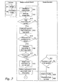
- Fig. 7 is an explanatory diagram showing one example of a flow of process performed by a whole position detection system. This figure also shows one example of a flow of an image analysis process executed by the image analysis board 13.
- the cameras 20 and 21 continuously perform imaging (#1) and forward a picture signal to the image analysis board 13 (#2).
- the image processing units 136a, b receive the picture signal from the cameras 20 and 21, convert the picture signal into digital data and develop it in the frame buffers 135a, b (#11).
- the CPU 131 binarizes the image data that was developed in the frame buffer 135a on a dot basis based on a predetermined threshold (#12), and select at least one part having a high brightness of the infrared rays on a dot basis (#13). For the selected part having a high brightness, i.e. each aggregate consisting of one or more high brightness dots, the CPU 131 calculates an area of each aggregate (#14). Further, the CPU 131 determines whether or not each of the calculated areas is within a predetermined size (#15), and when there are any aggregates of the high brightness dots having the predetermined size, acquires the barycentric coordinate of each high brightness aggregate (#16).
- the CPU 131 determines whether or not a degree of circularity of the aggregate whose barycentric coordinate was acquired is within a predetermined range (#17).
- the aggregate can be determined to be circular when the high brightness dots exist at a predetermined percentage in a circle having a predetermined radius with the acquired barycentric coordinate as the center thereof.
- the CPU 131 considers the high brightness aggregate that was determined to be circular as an image of the ball, and converts its barycentric coordinate in the frame buffer 135a into a coordinate in the frame buffer 135b. This coordinate conversion is performed when there is a gap in coordinates between the frame buffer 135a and the frame buffer b. Further, the CPU 131 reads out color information from image data at the coordinate position obtained by the conversion (#18). Thereafter, the CPU 131 writes the barycentric coordinate and the color information of the ball into the buffer 124 of the game machine 12.
- the CPU 121 of the game machine 12 refers to the buffer 124 every time the predetermined time ⁇ T2 has lapsed and reads out the latest position information and color information (#21, #22). The read out information is used for the collision detection in the game (#23).
- the game machine 12 performs the collision detection in the game using the position information written into the buffer 124 by carrying out this process every 1/60 sec, for example.
- Fig. 8 is a flow chart showing one example of a flow of game process performed by the game machine 12.
- the CPU 121 of the game machine 12 initiates the following processes when the power is turned on.
- Step S1-S2 The CPU 121 waits for a coin to be inserted while outputting a demo screen on the display (S1). When a coin is inserted (S2), a process proceeds to Step S3.
- Step S3 The CPU 121 executes a game program stored in the ROM 123. Upon the execution of the game program, the CPU 121 refers to the buffer 124 at necessary timing and uses, at the time of referring, the position information and color information that are written in the buffer 124 for processing a game.
- Step S4-S5 The CPU 121 executes the game until the game finishes (S4), and when the game is finished, determines whether the game is finished by clearing the game or by game over (S5).
- Step S6 The CPU 121 accepts from the player a selection whether or not he/she wishes to continue the game, and when the game is to be continued, returns to the aforementioned Step 3 and executes a new game. When the game is not to be continued, and when the game is finished by game over in the aforementioned step S4, a process returns to step S 1 and display the demo screen.
- a trajectory that is created on the infrared screen by an object can also be detected. For example, in a battle game in which a player fights an enemy character by operating a sword, whether or not the player has made a specific movement pattern using the sword, for example a movement in the shape of a cross, can be determined based on the trajectory of the sword on the infrared screen.
- an object to be detected is not limited to a ball but may be an arrow, a BB bullet, a sward-shaped stick or even a part of a player's body.
- a position of the glove may be detected.
- the present invention can be applied to various fields where a position of object in a space is detected, and more preferably, applied to a game field.
Landscapes
- Engineering & Computer Science (AREA)
- Multimedia (AREA)
- General Engineering & Computer Science (AREA)
- Human Computer Interaction (AREA)
- Theoretical Computer Science (AREA)
- Physics & Mathematics (AREA)
- General Physics & Mathematics (AREA)
- Health & Medical Sciences (AREA)
- General Health & Medical Sciences (AREA)
- Physical Education & Sports Medicine (AREA)
- Environmental & Geological Engineering (AREA)
- Radar, Positioning & Navigation (AREA)
- Length Measuring Devices By Optical Means (AREA)
- Closed-Circuit Television Systems (AREA)
- Geophysics And Detection Of Objects (AREA)
Applications Claiming Priority (2)
| Application Number | Priority Date | Filing Date | Title |
|---|---|---|---|
| JP2005218132A JP3934658B2 (ja) | 2005-07-28 | 2005-07-28 | 位置検出システム |
| PCT/JP2006/313818 WO2007013299A1 (fr) | 2005-07-28 | 2006-07-12 | Système de détection de position |
Publications (2)
| Publication Number | Publication Date |
|---|---|
| EP1908496A1 true EP1908496A1 (fr) | 2008-04-09 |
| EP1908496A4 EP1908496A4 (fr) | 2012-03-28 |
Family
ID=37683200
Family Applications (1)
| Application Number | Title | Priority Date | Filing Date |
|---|---|---|---|
| EP06780988A Withdrawn EP1908496A4 (fr) | 2005-07-28 | 2006-07-12 | Système de détection de position |
Country Status (7)
| Country | Link |
|---|---|
| US (1) | US7453582B2 (fr) |
| EP (1) | EP1908496A4 (fr) |
| JP (1) | JP3934658B2 (fr) |
| KR (1) | KR101017916B1 (fr) |
| CN (1) | CN101198383B (fr) |
| TW (1) | TW200708327A (fr) |
| WO (1) | WO2007013299A1 (fr) |
Cited By (1)
| Publication number | Priority date | Publication date | Assignee | Title |
|---|---|---|---|---|
| EP2335138A4 (fr) * | 2008-08-15 | 2012-12-19 | Qualcomm Inc | Détection multipoint améliorée |
Families Citing this family (53)
| Publication number | Priority date | Publication date | Assignee | Title |
|---|---|---|---|---|
| WO2008101183A2 (fr) * | 2007-02-15 | 2008-08-21 | Gesturetek, Inc. | Entrée améliorée en utilisant un rayonnement électromagnétique clignotant |
| JP2008306512A (ja) * | 2007-06-08 | 2008-12-18 | Nec Corp | 情報提供システム |
| JP4745316B2 (ja) * | 2007-11-07 | 2011-08-10 | シャープ株式会社 | 表示システムおよび指示位置の検出方法 |
| US10244190B2 (en) | 2009-03-02 | 2019-03-26 | Flir Systems, Inc. | Compact multi-spectrum imaging with fusion |
| US9948872B2 (en) | 2009-03-02 | 2018-04-17 | Flir Systems, Inc. | Monitor and control systems and methods for occupant safety and energy efficiency of structures |
| US9208542B2 (en) | 2009-03-02 | 2015-12-08 | Flir Systems, Inc. | Pixel-wise noise reduction in thermal images |
| WO2012170946A2 (fr) | 2011-06-10 | 2012-12-13 | Flir Systems, Inc. | Système d'imagerie infrarouge de faible puissance et à petit facteur de forme |
| US9843742B2 (en) | 2009-03-02 | 2017-12-12 | Flir Systems, Inc. | Thermal image frame capture using de-aligned sensor array |
| US9986175B2 (en) | 2009-03-02 | 2018-05-29 | Flir Systems, Inc. | Device attachment with infrared imaging sensor |
| US9451183B2 (en) | 2009-03-02 | 2016-09-20 | Flir Systems, Inc. | Time spaced infrared image enhancement |
| US9517679B2 (en) | 2009-03-02 | 2016-12-13 | Flir Systems, Inc. | Systems and methods for monitoring vehicle occupants |
| US9473681B2 (en) | 2011-06-10 | 2016-10-18 | Flir Systems, Inc. | Infrared camera system housing with metalized surface |
| US9674458B2 (en) | 2009-06-03 | 2017-06-06 | Flir Systems, Inc. | Smart surveillance camera systems and methods |
| USD765081S1 (en) | 2012-05-25 | 2016-08-30 | Flir Systems, Inc. | Mobile communications device attachment with camera |
| US9635285B2 (en) | 2009-03-02 | 2017-04-25 | Flir Systems, Inc. | Infrared imaging enhancement with fusion |
| US9998697B2 (en) | 2009-03-02 | 2018-06-12 | Flir Systems, Inc. | Systems and methods for monitoring vehicle occupants |
| US9235876B2 (en) | 2009-03-02 | 2016-01-12 | Flir Systems, Inc. | Row and column noise reduction in thermal images |
| US9756264B2 (en) | 2009-03-02 | 2017-09-05 | Flir Systems, Inc. | Anomalous pixel detection |
| US10757308B2 (en) | 2009-03-02 | 2020-08-25 | Flir Systems, Inc. | Techniques for device attachment with dual band imaging sensor |
| US10091439B2 (en) | 2009-06-03 | 2018-10-02 | Flir Systems, Inc. | Imager with array of multiple infrared imaging modules |
| US9819880B2 (en) | 2009-06-03 | 2017-11-14 | Flir Systems, Inc. | Systems and methods of suppressing sky regions in images |
| US9716843B2 (en) | 2009-06-03 | 2017-07-25 | Flir Systems, Inc. | Measurement device for electrical installations and related methods |
| US9292909B2 (en) | 2009-06-03 | 2016-03-22 | Flir Systems, Inc. | Selective image correction for infrared imaging devices |
| US9756262B2 (en) | 2009-06-03 | 2017-09-05 | Flir Systems, Inc. | Systems and methods for monitoring power systems |
| US9843743B2 (en) | 2009-06-03 | 2017-12-12 | Flir Systems, Inc. | Infant monitoring systems and methods using thermal imaging |
| US9706138B2 (en) | 2010-04-23 | 2017-07-11 | Flir Systems, Inc. | Hybrid infrared sensor array having heterogeneous infrared sensors |
| US9848134B2 (en) | 2010-04-23 | 2017-12-19 | Flir Systems, Inc. | Infrared imager with integrated metal layers |
| US9207708B2 (en) | 2010-04-23 | 2015-12-08 | Flir Systems, Inc. | Abnormal clock rate detection in imaging sensor arrays |
| JP5307108B2 (ja) * | 2010-10-29 | 2013-10-02 | 株式会社コナミデジタルエンタテインメント | 検出システム、それが適用された電子黒板装置、その制御方法及び、コンピュータプログラム |
| US9706137B2 (en) | 2011-06-10 | 2017-07-11 | Flir Systems, Inc. | Electrical cabinet infrared monitor |
| US10169666B2 (en) | 2011-06-10 | 2019-01-01 | Flir Systems, Inc. | Image-assisted remote control vehicle systems and methods |
| EP2719165B1 (fr) | 2011-06-10 | 2018-05-02 | Flir Systems, Inc. | Techniques de correction de non-uniformité pour dispositifs d'imagerie infrarouge |
| US9143703B2 (en) | 2011-06-10 | 2015-09-22 | Flir Systems, Inc. | Infrared camera calibration techniques |
| US10051210B2 (en) | 2011-06-10 | 2018-08-14 | Flir Systems, Inc. | Infrared detector array with selectable pixel binning systems and methods |
| US10841508B2 (en) | 2011-06-10 | 2020-11-17 | Flir Systems, Inc. | Electrical cabinet infrared monitor systems and methods |
| US10079982B2 (en) | 2011-06-10 | 2018-09-18 | Flir Systems, Inc. | Determination of an absolute radiometric value using blocked infrared sensors |
| US9058653B1 (en) | 2011-06-10 | 2015-06-16 | Flir Systems, Inc. | Alignment of visible light sources based on thermal images |
| US9235023B2 (en) | 2011-06-10 | 2016-01-12 | Flir Systems, Inc. | Variable lens sleeve spacer |
| US10389953B2 (en) | 2011-06-10 | 2019-08-20 | Flir Systems, Inc. | Infrared imaging device having a shutter |
| WO2012170954A2 (fr) | 2011-06-10 | 2012-12-13 | Flir Systems, Inc. | Traitement d'image à base de lignes et système de mémoire souple |
| US9961277B2 (en) | 2011-06-10 | 2018-05-01 | Flir Systems, Inc. | Infrared focal plane array heat spreaders |
| US9509924B2 (en) | 2011-06-10 | 2016-11-29 | Flir Systems, Inc. | Wearable apparatus with integrated infrared imaging module |
| US9900526B2 (en) | 2011-06-10 | 2018-02-20 | Flir Systems, Inc. | Techniques to compensate for calibration drifts in infrared imaging devices |
| US9811884B2 (en) | 2012-07-16 | 2017-11-07 | Flir Systems, Inc. | Methods and systems for suppressing atmospheric turbulence in images |
| JP6111706B2 (ja) | 2013-02-01 | 2017-04-12 | セイコーエプソン株式会社 | 位置検出装置、調整方法、および調整プログラム |
| JP6081830B2 (ja) * | 2013-03-12 | 2017-02-15 | 新日本無線株式会社 | 反射型フォトセンサを用いた位置検出装置 |
| US9973692B2 (en) | 2013-10-03 | 2018-05-15 | Flir Systems, Inc. | Situational awareness by compressed display of panoramic views |
| US11297264B2 (en) | 2014-01-05 | 2022-04-05 | Teledyne Fur, Llc | Device attachment with dual band imaging sensor |
| JP2018005806A (ja) * | 2016-07-08 | 2018-01-11 | 株式会社スクウェア・エニックス | 位置特定プログラム、コンピュータ装置、位置特定方法、及び、位置特定システム |
| CN109621402B (zh) * | 2019-01-03 | 2022-05-27 | 上海亿湾特训练设备科技有限公司 | 一种影像实弹射击和激光射击通用的定位系统及方法 |
| KR102803040B1 (ko) * | 2019-01-11 | 2025-05-09 | 한국전자통신연구원 | 스크린 충돌위치 인식 시스템 및 방법 |
| CN111408118A (zh) * | 2020-03-23 | 2020-07-14 | 李志刚 | 一种体育设备 |
| CN113587734A (zh) * | 2021-07-12 | 2021-11-02 | 孙立峰 | 一种基于近红外光成像的视觉识别报靶方法 |
Family Cites Families (14)
| Publication number | Priority date | Publication date | Assignee | Title |
|---|---|---|---|---|
| JPS596078A (ja) * | 1982-06-30 | 1984-01-13 | 美津濃株式会社 | 投球練習装置における投球目標と受球位置との相関関係を提示する方法 |
| US5328190A (en) * | 1992-08-04 | 1994-07-12 | Dart International, Inc. | Method and apparatus enabling archery practice |
| US5649706A (en) * | 1994-09-21 | 1997-07-22 | Treat, Jr.; Erwin C. | Simulator and practice method |
| JP3183820B2 (ja) * | 1996-02-22 | 2001-07-09 | 住友ゴム工業株式会社 | 飛行物体の位置測定装置及び位置測定方法 |
| JP3794180B2 (ja) * | 1997-11-11 | 2006-07-05 | セイコーエプソン株式会社 | 座標入力システム及び座標入力装置 |
| JP2000148375A (ja) * | 1998-11-11 | 2000-05-26 | Seiko Epson Corp | 入力システム及び投射型表示システム |
| JP2001350576A (ja) * | 2000-06-08 | 2001-12-21 | Clarion Co Ltd | ビジュアルインターフェイス |
| US8287374B2 (en) * | 2000-07-07 | 2012-10-16 | Pryor Timothy R | Reconfigurable control displays for games, toys, and other applications |
| TW539568B (en) | 2001-04-27 | 2003-07-01 | Tvio Technology Co Ltd | Location information detection system and game machine using the location information detection system |
| JP3662863B2 (ja) | 2001-07-31 | 2005-06-22 | Necパーソナルプロダクツ株式会社 | 光銃、標的ボックス、射撃ボックス、及び、光銃の射撃システム |
| JP3920067B2 (ja) | 2001-10-09 | 2007-05-30 | 株式会社イーアイティー | 座標入力装置 |
| JP3867205B2 (ja) * | 2002-08-30 | 2007-01-10 | カシオ計算機株式会社 | 指示位置検出装置、及び指示位置検出システム、並びに指示位置検出方法 |
| JP2004101317A (ja) * | 2002-09-09 | 2004-04-02 | Matsushita Electric Ind Co Ltd | 位置検出方法、位置検出装置及び電子黒板 |
| JP2005052306A (ja) | 2003-08-01 | 2005-03-03 | Sony Corp | 位置検出システム |
-
2005
- 2005-07-28 JP JP2005218132A patent/JP3934658B2/ja not_active Expired - Fee Related
-
2006
- 2006-07-12 EP EP06780988A patent/EP1908496A4/fr not_active Withdrawn
- 2006-07-12 WO PCT/JP2006/313818 patent/WO2007013299A1/fr not_active Ceased
- 2006-07-12 CN CN2006800211947A patent/CN101198383B/zh active Active
- 2006-07-12 KR KR1020077024278A patent/KR101017916B1/ko not_active Expired - Fee Related
- 2006-07-13 TW TW095125715A patent/TW200708327A/zh unknown
-
2008
- 2008-01-28 US US12/021,038 patent/US7453582B2/en active Active
Cited By (1)
| Publication number | Priority date | Publication date | Assignee | Title |
|---|---|---|---|---|
| EP2335138A4 (fr) * | 2008-08-15 | 2012-12-19 | Qualcomm Inc | Détection multipoint améliorée |
Also Published As
| Publication number | Publication date |
|---|---|
| KR20070116901A (ko) | 2007-12-11 |
| WO2007013299A1 (fr) | 2007-02-01 |
| US7453582B2 (en) | 2008-11-18 |
| KR101017916B1 (ko) | 2011-03-04 |
| US20080165342A1 (en) | 2008-07-10 |
| JP2007029478A (ja) | 2007-02-08 |
| TWI307637B (fr) | 2009-03-21 |
| CN101198383A (zh) | 2008-06-11 |
| JP3934658B2 (ja) | 2007-06-20 |
| CN101198383B (zh) | 2011-01-26 |
| TW200708327A (en) | 2007-03-01 |
| EP1908496A4 (fr) | 2012-03-28 |
Similar Documents
| Publication | Publication Date | Title |
|---|---|---|
| US7453582B2 (en) | Position detection system | |
| US8791901B2 (en) | Object tracking with projected reference patterns | |
| US9799121B2 (en) | Control device for communicating visual information | |
| US9682320B2 (en) | Inertially trackable hand-held controller | |
| JP5626939B2 (ja) | 運動するボールに対するセンシング処理装置、センシング処理方法及びそれを用いた仮想ゴルフシミュレーション装置 | |
| CN102449641A (zh) | 用于对象跟踪的颜色校准 | |
| JP2000003445A (ja) | 情報抽出方法および情報抽出装置および記録媒体 | |
| US20050026703A1 (en) | Position detection system, game machine, program, and information storage medium | |
| RU2606583C2 (ru) | Способ и устройство для определения положения спортивного снаряда на площадке | |
| JP3443415B2 (ja) | ゲーム装置 | |
| CN101378813B (zh) | 具有不正当行为防止功能的游戏装置、游戏中的不正当行为防止方法 | |
| JP2001062149A (ja) | スポット光位置検出システムおよびシミュレータ | |
| JP4218963B2 (ja) | 情報抽出方法、情報抽出装置及び記録媒体 | |
| HK1119104A (en) | Position detection system | |
| JP5638797B2 (ja) | ゲーム装置およびゲームプログラム | |
| JP2011004797A (ja) | ゲーム装置 | |
| JP7243708B2 (ja) | 情報処理装置、情報処理方法、およびプログラム | |
| JP7100898B2 (ja) | ゲーム機及びそのコンピュータプログラム | |
| JP5583398B2 (ja) | ゲームプログラム及びゲーム装置 | |
| JP4923214B2 (ja) | プレイヤー身体画像を感知可能な電子ゲームコントローラ及びその方法 | |
| JP2001004327A (ja) | スポット光位置検出システム、シミュレータ | |
| JP3554516B2 (ja) | シューティングゲーム用の装置、位置検出用の装置及び情報記憶媒体 | |
| JP3418156B2 (ja) | 撮影ゲーム装置、撮影ゲーム処理方法および情報記憶媒体 | |
| JP2001340635A (ja) | ゲーム装置、ゲーム処理方法および情報記憶媒体 | |
| HK1086779A1 (zh) | 游戏图像的显示控制方法和游戏装置 |
Legal Events
| Date | Code | Title | Description |
|---|---|---|---|
| PUAI | Public reference made under article 153(3) epc to a published international application that has entered the european phase |
Free format text: ORIGINAL CODE: 0009012 |
|
| 17P | Request for examination filed |
Effective date: 20080208 |
|
| AK | Designated contracting states |
Kind code of ref document: A1 Designated state(s): DE FR GB IT |
|
| DAX | Request for extension of the european patent (deleted) | ||
| RBV | Designated contracting states (corrected) |
Designated state(s): DE FR GB IT |
|
| REG | Reference to a national code |
Ref country code: HK Ref legal event code: DE Ref document number: 1119104 Country of ref document: HK |
|
| A4 | Supplementary search report drawn up and despatched |
Effective date: 20120229 |
|
| RIC1 | Information provided on ipc code assigned before grant |
Ipc: A63F 13/04 20060101ALI20120223BHEP Ipc: A63B 1/00 20060101AFI20120223BHEP |
|
| GRAP | Despatch of communication of intention to grant a patent |
Free format text: ORIGINAL CODE: EPIDOSNIGR1 |
|
| INTG | Intention to grant announced |
Effective date: 20130425 |
|
| STAA | Information on the status of an ep patent application or granted ep patent |
Free format text: STATUS: THE APPLICATION IS DEEMED TO BE WITHDRAWN |
|
| 18D | Application deemed to be withdrawn |
Effective date: 20130906 |
|
| REG | Reference to a national code |
Ref country code: HK Ref legal event code: WD Ref document number: 1119104 Country of ref document: HK |