EP1906513A2 - Linearmotor und Linearmotr versehene Werkzeugmaschine - Google Patents
Linearmotor und Linearmotr versehene Werkzeugmaschine Download PDFInfo
- Publication number
- EP1906513A2 EP1906513A2 EP07017228A EP07017228A EP1906513A2 EP 1906513 A2 EP1906513 A2 EP 1906513A2 EP 07017228 A EP07017228 A EP 07017228A EP 07017228 A EP07017228 A EP 07017228A EP 1906513 A2 EP1906513 A2 EP 1906513A2
- Authority
- EP
- European Patent Office
- Prior art keywords
- magnet member
- linear motor
- magnetic substance
- magnet
- coil
- Prior art date
- Legal status (The legal status is an assumption and is not a legal conclusion. Google has not performed a legal analysis and makes no representation as to the accuracy of the status listed.)
- Withdrawn
Links
- 230000005291 magnetic effect Effects 0.000 claims abstract description 123
- 239000000126 substance Substances 0.000 claims abstract description 84
- 230000005764 inhibitory process Effects 0.000 claims description 18
- 230000005284 excitation Effects 0.000 claims description 10
- 230000002093 peripheral effect Effects 0.000 description 9
- 230000007246 mechanism Effects 0.000 description 8
- 238000001816 cooling Methods 0.000 description 4
- 230000004907 flux Effects 0.000 description 4
- XEEYBQQBJWHFJM-UHFFFAOYSA-N Iron Chemical compound [Fe] XEEYBQQBJWHFJM-UHFFFAOYSA-N 0.000 description 2
- 238000010586 diagram Methods 0.000 description 2
- 230000003028 elevating effect Effects 0.000 description 2
- 230000005484 gravity Effects 0.000 description 2
- 238000000034 method Methods 0.000 description 2
- 230000008569 process Effects 0.000 description 2
- 230000009467 reduction Effects 0.000 description 2
- 238000004891 communication Methods 0.000 description 1
- 239000000110 cooling liquid Substances 0.000 description 1
- 230000008878 coupling Effects 0.000 description 1
- 238000010168 coupling process Methods 0.000 description 1
- 238000005859 coupling reaction Methods 0.000 description 1
- 230000002950 deficient Effects 0.000 description 1
- 230000005294 ferromagnetic effect Effects 0.000 description 1
- 230000010354 integration Effects 0.000 description 1
- 229910052742 iron Inorganic materials 0.000 description 1
- 238000003754 machining Methods 0.000 description 1
- 238000012986 modification Methods 0.000 description 1
- 230000004048 modification Effects 0.000 description 1
- 230000002265 prevention Effects 0.000 description 1
Images

Classifications
-
- H—ELECTRICITY
- H02—GENERATION; CONVERSION OR DISTRIBUTION OF ELECTRIC POWER
- H02K—DYNAMO-ELECTRIC MACHINES
- H02K41/00—Propulsion systems in which a rigid body is moved along a path due to dynamo-electric interaction between the body and a magnetic field travelling along the path
- H02K41/02—Linear motors; Sectional motors
- H02K41/03—Synchronous motors; Motors moving step by step; Reluctance motors
- H02K41/031—Synchronous motors; Motors moving step by step; Reluctance motors of the permanent magnet type
-
- H—ELECTRICITY
- H02—GENERATION; CONVERSION OR DISTRIBUTION OF ELECTRIC POWER
- H02K—DYNAMO-ELECTRIC MACHINES
- H02K41/00—Propulsion systems in which a rigid body is moved along a path due to dynamo-electric interaction between the body and a magnetic field travelling along the path
- H02K41/02—Linear motors; Sectional motors
-
- H—ELECTRICITY
- H02—GENERATION; CONVERSION OR DISTRIBUTION OF ELECTRIC POWER
- H02K—DYNAMO-ELECTRIC MACHINES
- H02K1/00—Details of the magnetic circuit
- H02K1/06—Details of the magnetic circuit characterised by the shape, form or construction
- H02K1/12—Stationary parts of the magnetic circuit
- H02K1/14—Stator cores with salient poles
- H02K1/145—Stator cores with salient poles having an annular coil, e.g. of the claw-pole type
-
- H—ELECTRICITY
- H02—GENERATION; CONVERSION OR DISTRIBUTION OF ELECTRIC POWER
- H02K—DYNAMO-ELECTRIC MACHINES
- H02K5/00—Casings; Enclosures; Supports
- H02K5/04—Casings or enclosures characterised by the shape, form or construction thereof
- H02K5/16—Means for supporting bearings, e.g. insulating supports or means for fitting bearings in the bearing-shields
- H02K5/167—Means for supporting bearings, e.g. insulating supports or means for fitting bearings in the bearing-shields using sliding-contact or spherical cap bearings
- H02K5/1672—Means for supporting bearings, e.g. insulating supports or means for fitting bearings in the bearing-shields using sliding-contact or spherical cap bearings radially supporting the rotary shaft at both ends of the rotor
-
- H—ELECTRICITY
- H02—GENERATION; CONVERSION OR DISTRIBUTION OF ELECTRIC POWER
- H02K—DYNAMO-ELECTRIC MACHINES
- H02K7/00—Arrangements for handling mechanical energy structurally associated with dynamo-electric machines, e.g. structural association with mechanical driving motors or auxiliary dynamo-electric machines
- H02K7/10—Structural association with clutches, brakes, gears, pulleys or mechanical starters
- H02K7/118—Structural association with clutches, brakes, gears, pulleys or mechanical starters with starting devices
- H02K7/1185—Structural association with clutches, brakes, gears, pulleys or mechanical starters with starting devices with a mechanical one-way direction control, i.e. with means for reversing the direction of rotation of the rotor
Definitions
- the predetermined axial direction may be a vertical direction
- the magnet member may be a movable-side member
- the coil member may be a static-side member.
- the magnetic substance may be located in the vicinity of an upper end of the coil member to inhibit the magnet member from falling down. This configuration can prevent the magnet member from falling down inadvertently.
- the magnetic substance is preferably installed at a height such that with the magnet member moved to a top dead center with respect to the coil member, the center of the vertical width of the magnetic substance is positioned in the vicinity of a center position of the vertical width between any magnetic poles of the N poles and the S poles alternately arranged in the magnet member.
- the magnet member has a plurality of unit magnets having respective N poles and S poles, and stacked so that the magnetic poles of the same polarity lie opposite each other, the position of a repulsion surface that is an overlapping surface on which the same polarities of the unit magnets overlap coincides with the center position of the vertical width between the magnetic poles.
- the predetermined axial direction is the vertical direction
- the magnet member is the movable-side member
- the coil member is the static-side member and where the magnetic substance is located in the vicinity of the upper end of the coil member to inhibit the magnet member from falling down
- the simple configuration can be used to prevent the magnet member from falling down inadvertently when the power supply is turned off.
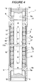
- Figure 4 shows another embodiment of the present invention.
- the axial position of the magnetic substance 13 is such that when the magnet member 2 moves downward relative to the coil member 3, the magnetic substance 13 falls outside the range of the magnets of the magnet member 2.
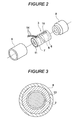
- the other arrangements of the present invention are similar to those of the first embodiment, shown in Figure 1 to Figure 3.
- the magnetic attractive force of the magnet member 2 acting on the magnetic substance 13 prevents the magnet member 2 from falling down.
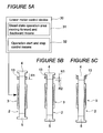
- the magnet member 2 performs a moving-forward or -backward operation
- the magnet member 2 performs the operation in the steady-state operation area R2, located below the fall-down inhibition enabled area R1. This prevents the magnetic substance 13 from resisting the operation or reduces the degree to which the magnetic substance 13 resists the operation.
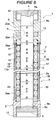
- the linear motor control device can thus prevent the magnet member 2 from falling down when the power supply is turned off. Further, during operation, the linear motor control device can prevent the fall-down preventing means from imposing excess loads.
Landscapes
- Engineering & Computer Science (AREA)
- Physics & Mathematics (AREA)
- Chemical & Material Sciences (AREA)
- Combustion & Propulsion (AREA)
- Electromagnetism (AREA)
- Power Engineering (AREA)
- Linear Motors (AREA)
- Reciprocating, Oscillating Or Vibrating Motors (AREA)
Applications Claiming Priority (1)
| Application Number | Priority Date | Filing Date | Title |
|---|---|---|---|
| JP2006264352A JP2008086144A (ja) | 2006-09-28 | 2006-09-28 | リニアモータおよびそれを搭載した工作機械 |
Publications (2)
| Publication Number | Publication Date |
|---|---|
| EP1906513A2 true EP1906513A2 (de) | 2008-04-02 |
| EP1906513A3 EP1906513A3 (de) | 2016-04-06 |
Family
ID=38514968
Family Applications (1)
| Application Number | Title | Priority Date | Filing Date |
|---|---|---|---|
| EP07017228.3A Withdrawn EP1906513A3 (de) | 2006-09-28 | 2007-09-03 | Linearmotor und Linearmotr versehene Werkzeugmaschine |
Country Status (6)
| Country | Link |
|---|---|
| US (1) | US7768159B2 (de) |
| EP (1) | EP1906513A3 (de) |
| JP (1) | JP2008086144A (de) |
| KR (1) | KR101064544B1 (de) |
| CN (1) | CN101154877B (de) |
| TW (1) | TW200901603A (de) |
Cited By (3)
| Publication number | Priority date | Publication date | Assignee | Title |
|---|---|---|---|---|
| JP2013009564A (ja) * | 2011-06-27 | 2013-01-10 | Sanyo Denki Co Ltd | リニアモータ |
| AT509090B1 (de) * | 2009-12-03 | 2014-03-15 | Andritz Tech & Asset Man Gmbh | Presse zum erzeugen einer druckkraft für die bearbeitung eines werkstücks |
| EP2784920A3 (de) * | 2013-03-26 | 2016-09-07 | Sanyo Denki Co., Ltd. | Linearmotor |
Families Citing this family (19)
| Publication number | Priority date | Publication date | Assignee | Title |
|---|---|---|---|---|
| TWI411481B (zh) * | 2007-10-30 | 2013-10-11 | Toshiba Machine Co Ltd | 精密軋輥車床 |
| JP4586088B2 (ja) * | 2008-08-19 | 2010-11-24 | ファナック株式会社 | 往復直線駆動装置 |
| JP2010288418A (ja) * | 2009-06-15 | 2010-12-24 | Tamagawa Seiki Co Ltd | 円筒型リニアモータ |
| JP5438498B2 (ja) * | 2009-12-24 | 2014-03-12 | 山洋電気株式会社 | リニア同期モータ |
| WO2011144006A1 (zh) * | 2010-05-18 | 2011-11-24 | Jian Xingliang | 永磁体电磁驱动装置、控制方法及专用控制电路 |
| JP5473776B2 (ja) * | 2010-05-20 | 2014-04-16 | 株式会社コガネイ | リニアモータ |
| JP5603724B2 (ja) * | 2010-09-21 | 2014-10-08 | カヤバ工業株式会社 | リニアアクチュエータ |
| JP5457986B2 (ja) * | 2010-09-21 | 2014-04-02 | カヤバ工業株式会社 | リニアアクチュエータ |
| JP5888867B2 (ja) * | 2011-03-31 | 2016-03-22 | 日本電産コパル株式会社 | 振動アクチュエータ |
| JP5981103B2 (ja) * | 2011-06-27 | 2016-08-31 | 山洋電気株式会社 | リニアモータ |
| JP6059870B2 (ja) * | 2011-12-08 | 2017-01-11 | Juki株式会社 | リニアアクチュエータおよび電子部品実装装置 |
| JP5927058B2 (ja) * | 2012-06-19 | 2016-05-25 | Kyb株式会社 | リニアアクチュエータ及び溝加工方法 |
| JP5933379B2 (ja) * | 2012-07-25 | 2016-06-08 | Kyb株式会社 | リニアアクチュエータ |
| JP5997960B2 (ja) * | 2012-07-25 | 2016-09-28 | Kyb株式会社 | リニアアクチュエータ |
| KR101338086B1 (ko) * | 2012-10-08 | 2013-12-06 | 현대자동차주식회사 | 환경자동차용 모터 |
| WO2014194140A2 (en) * | 2013-05-29 | 2014-12-04 | Active Signal Technologies, Inc. | Electromagnetic opposing field actuators |
| CN107807318A (zh) * | 2016-08-31 | 2018-03-16 | 科大国盾量子技术股份有限公司 | 一种电子元器件测试夹具 |
| WO2019123493A1 (en) * | 2017-12-21 | 2019-06-27 | Ceme S.P.A | A mass shifting mechanism between twin equilibrium points, and electro-pump or electro-valve having such shifting mechanism |
| DE102023111322A1 (de) | 2023-05-02 | 2024-11-07 | Compact Motion GmbH | Linearmotor |
Family Cites Families (21)
| Publication number | Priority date | Publication date | Assignee | Title |
|---|---|---|---|---|
| US4692673A (en) * | 1982-02-22 | 1987-09-08 | Sanford D. DeLong | Electromagnetic reciprocating pump and motor means |
| JPH01164256A (ja) * | 1987-12-18 | 1989-06-28 | Aisin Seiki Co Ltd | リニア発電機 |
| JP2833118B2 (ja) | 1989-08-05 | 1998-12-09 | 富士電機株式会社 | 垂直搬送装置 |
| US5691582A (en) * | 1993-03-23 | 1997-11-25 | Coors Brewing Company | Can body maker with linear motor redraw actuator |
| JPH06335230A (ja) * | 1993-05-18 | 1994-12-02 | Hitachi Metals Ltd | 永久磁石式リニア同期モータ |
| JPH10313566A (ja) | 1997-05-12 | 1998-11-24 | Jii M C:Kk | リニアモータ |
| JP2001520498A (ja) * | 1997-10-15 | 2001-10-30 | アドバンスト モーション テクノロジーズ リミテッド ライアビリティー カンパニー | リニア電磁機械 |
| US5896076A (en) * | 1997-12-29 | 1999-04-20 | Motran Ind Inc | Force actuator with dual magnetic operation |
| EP1001512A3 (de) * | 1998-11-10 | 2001-02-14 | Asm Lithography B.V. | Betätiger und Wandler |
| US6239517B1 (en) * | 1999-02-19 | 2001-05-29 | Hitachi Koki Co., Ltd. | Linear shuttle motor assembly and a controller therefor |
| IT1309797B1 (it) * | 1999-05-06 | 2002-01-30 | Boscato & Dalla Fontana | Meccanismo maschietto per la pressatura di gocce di vetro fusodentro lo stampo sbozzatore di una macchina i.s. per la produzione |
| US6363750B1 (en) * | 2000-02-25 | 2002-04-02 | Chris D. Chiodo | Automatic pipette puller and forge |
| JP2001352747A (ja) | 2000-06-09 | 2001-12-21 | Aida Eng Ltd | リニアモータおよびこれを駆動源とするプレス成形装置 |
| US6701748B1 (en) * | 2000-10-06 | 2004-03-09 | Libbey Glass Inc. | Glassware machine |
| JP2004088992A (ja) * | 2002-05-24 | 2004-03-18 | Murata Mfg Co Ltd | ボイスコイル型リニアアクチュエータ及びこのアクチュエータを用いた装置、並びにこのアクチュエータの製造方法 |
| JP2004064852A (ja) * | 2002-07-26 | 2004-02-26 | Matsushita Refrig Co Ltd | リニアモータ及びリニアモータコンプレッサ |
| WO2004012260A1 (ja) * | 2002-07-30 | 2004-02-05 | Tamura Corporation | 精密加工用ステージ装置 |
| JP4032911B2 (ja) | 2002-10-02 | 2008-01-16 | 豊和工業株式会社 | リニアモータ駆動式工作機械の主軸ヘッド落下防止装置 |
| JP2004364399A (ja) * | 2003-06-04 | 2004-12-24 | Sankyo Seiki Mfg Co Ltd | リニアモータ |
| JP2005204448A (ja) * | 2004-01-16 | 2005-07-28 | Yushin Precision Equipment Co Ltd | リニアモータの非接触式ブレーキ機構 |
| JP2006187079A (ja) * | 2004-12-27 | 2006-07-13 | Hitachi Ltd | 円筒型リニアモータ,電磁サスペンション及びそれを用いた車両 |
-
2006
- 2006-09-28 JP JP2006264352A patent/JP2008086144A/ja active Pending
-
2007
- 2007-09-03 EP EP07017228.3A patent/EP1906513A3/de not_active Withdrawn
- 2007-09-07 TW TW096133559A patent/TW200901603A/zh unknown
- 2007-09-25 US US11/902,687 patent/US7768159B2/en not_active Expired - Fee Related
- 2007-09-27 KR KR1020070097457A patent/KR101064544B1/ko not_active Expired - Fee Related
- 2007-09-28 CN CN2007101531525A patent/CN101154877B/zh not_active Expired - Fee Related
Cited By (3)
| Publication number | Priority date | Publication date | Assignee | Title |
|---|---|---|---|---|
| AT509090B1 (de) * | 2009-12-03 | 2014-03-15 | Andritz Tech & Asset Man Gmbh | Presse zum erzeugen einer druckkraft für die bearbeitung eines werkstücks |
| JP2013009564A (ja) * | 2011-06-27 | 2013-01-10 | Sanyo Denki Co Ltd | リニアモータ |
| EP2784920A3 (de) * | 2013-03-26 | 2016-09-07 | Sanyo Denki Co., Ltd. | Linearmotor |
Also Published As
| Publication number | Publication date |
|---|---|
| JP2008086144A (ja) | 2008-04-10 |
| US20080079522A1 (en) | 2008-04-03 |
| CN101154877A (zh) | 2008-04-02 |
| TW200901603A (en) | 2009-01-01 |
| KR101064544B1 (ko) | 2011-09-14 |
| CN101154877B (zh) | 2012-06-20 |
| EP1906513A3 (de) | 2016-04-06 |
| US7768159B2 (en) | 2010-08-03 |
| KR20080029855A (ko) | 2008-04-03 |
Similar Documents
| Publication | Publication Date | Title |
|---|---|---|
| US7768159B2 (en) | Linear motor and machine tool having the same mounted thereon | |
| EP1906514B1 (de) | Linearmotor und Werkzeugmaschine mit darauf montiertem Linearmotor | |
| US7752880B2 (en) | Linear motor mounted press machine and method for controlling linear motor mounted press machine | |
| EP4153887B1 (de) | Integrierter motor mit linearantrieb | |
| US7523699B2 (en) | Linear motor mounted press machine and method for controlling linear motor mounted press machine | |
| US5284411A (en) | Conveyor for conveying workpieces in a vacuum chamber | |
| US7252462B2 (en) | Spindle unit having pressure foot | |
| US7642678B2 (en) | Linear motor and machine tool having the same mounted thereon | |
| JP5383135B2 (ja) | 直接駆動式の往復動及び旋回動を行なうアクチュエータ付き工具交換装置 | |
| JPH1133863A (ja) | 工具交換装置及び工具交換用の押出し装置 | |
| US20080041243A1 (en) | Linear motor mounted press machine and press working method | |
| JP2009090457A6 (ja) | 直接駆動式の往復動及び旋回動を行なうアクチュエータ付き工具交換装置 | |
| US11649855B1 (en) | Contaminant-free work piece processing system | |
| EP1892819A2 (de) | Mehrfach-Linearmotor und Werkzeugmaschine mit darauf montiertem Mehrfach-Linearmotor | |
| KR100821992B1 (ko) | 탁상형 엔씨 밀링머신 | |
| JP4472042B2 (ja) | クランプ装置 | |
| JP2008048564A (ja) | リニアモータおよびそれを搭載した工作機械 | |
| CN219313648U (zh) | 用于导向套仓储系统的导向套储料结构及导向套储料装置 | |
| JP7158661B2 (ja) | 縦型リニアアクチュエータ | |
| JP2008048567A (ja) | リニアモータおよびそれを搭載した工作機械 | |
| JP2016034693A (ja) | 機構分割式無心インデックス装置 | |
| JP2007054846A (ja) | パンチプレス | |
| JPS6277129A (ja) | ダイセツトの支持装置 | |
| JP2016010821A (ja) | 旋削加工装置の工具送り装置 |
Legal Events
| Date | Code | Title | Description |
|---|---|---|---|
| PUAI | Public reference made under article 153(3) epc to a published international application that has entered the european phase |
Free format text: ORIGINAL CODE: 0009012 |
|
| AK | Designated contracting states |
Kind code of ref document: A2 Designated state(s): AT BE BG CH CY CZ DE DK EE ES FI FR GB GR HU IE IS IT LI LT LU LV MC MT NL PL PT RO SE SI SK TR |
|
| AX | Request for extension of the european patent |
Extension state: AL BA HR MK YU |
|
| RAP1 | Party data changed (applicant data changed or rights of an application transferred) |
Owner name: MURATA MACHINERY, LTD. |
|
| PUAL | Search report despatched |
Free format text: ORIGINAL CODE: 0009013 |
|
| AK | Designated contracting states |
Kind code of ref document: A3 Designated state(s): AT BE BG CH CY CZ DE DK EE ES FI FR GB GR HU IE IS IT LI LT LU LV MC MT NL PL PT RO SE SI SK TR |
|
| AX | Request for extension of the european patent |
Extension state: AL BA HR MK RS |
|
| RIC1 | Information provided on ipc code assigned before grant |
Ipc: H02K 7/118 20060101ALN20160226BHEP Ipc: H02K 41/03 20060101AFI20160226BHEP Ipc: H02K 5/167 20060101ALN20160226BHEP Ipc: H02K 1/14 20060101ALN20160226BHEP |
|
| AKX | Designation fees paid |
Designated state(s): DE IT |
|
| AXX | Extension fees paid |
Extension state: RS Extension state: MK Extension state: BA Extension state: AL Extension state: HR |
|
| STAA | Information on the status of an ep patent application or granted ep patent |
Free format text: STATUS: THE APPLICATION IS DEEMED TO BE WITHDRAWN |
|
| 18D | Application deemed to be withdrawn |
Effective date: 20161007 |