EP1906510A2 - Moteur sans balai et appareil à direction assistée électrique le comprenant - Google Patents
Moteur sans balai et appareil à direction assistée électrique le comprenant Download PDFInfo
- Publication number
- EP1906510A2 EP1906510A2 EP07117175A EP07117175A EP1906510A2 EP 1906510 A2 EP1906510 A2 EP 1906510A2 EP 07117175 A EP07117175 A EP 07117175A EP 07117175 A EP07117175 A EP 07117175A EP 1906510 A2 EP1906510 A2 EP 1906510A2
- Authority
- EP
- European Patent Office
- Prior art keywords
- teeth
- width
- brushless motor
- rotor
- tooth
- Prior art date
- Legal status (The legal status is an assumption and is not a legal conclusion. Google has not performed a legal analysis and makes no representation as to the accuracy of the status listed.)
- Withdrawn
Links
Images


Classifications
-
- H—ELECTRICITY
- H02—GENERATION; CONVERSION OR DISTRIBUTION OF ELECTRIC POWER
- H02K—DYNAMO-ELECTRIC MACHINES
- H02K29/00—Motors or generators having non-mechanical commutating devices, e.g. discharge tubes or semiconductor devices
- H02K29/03—Motors or generators having non-mechanical commutating devices, e.g. discharge tubes or semiconductor devices with a magnetic circuit specially adapted for avoiding torque ripples or self-starting problems
Definitions
- the present invention relates to a brushless motor provided with a permanent magnet for forming a magnetic field and also relates to an electric power steering apparatus, which applies steering assist force to a steering mechanism in a vehicle, incorporating a brushless motor.
- an electric power steering apparatus for applying steering assist force to a steering mechanism by driving an electric motor, such as a brushless motor, in accordance with steering torque imparted to a steering wheel (handle) by a driver.
- a permanent-magnet motor which includes a stator around which a coil is wound and a rotor provided with a permanent magnet, are used as a brushless motor incorporated in the conventional electric power steering apparatus in many cases.
- the permanent-magnet motor may be suffered from cogging torque.
- the cogging torque is caused by a magnetic attraction force between a core of the stator and a magnetic pole (magnet) of the rotor in the state where electric current is not supplied to the coil of he stator.
- the foregoing cogging torque causes deterioration of steering feeling in the electric power steering apparatus. Accordingly, various attempts have been performed to reduce magnitude of the cogging torque. For example, it is known that the cogging torque is reduced by appropriately defining the number of the poles of the permanent magnets and the number of poles (teeth) provided in the stator. The number of the poles (teeth) in the stator is also referred to as slot number because this number is same as the number of spaces (slots) interposed between two adjacent poles (teeth).
- An 8poles-9slots type electric motor which includes eight poles in a rotor and nine slots in a stator, is incorporated in an electric power steering apparatus.
- Such power steering apparatus is described in non-examined Patent Publication JP 2001-275325 , for example.
- a 10poles-12slots type electric motor which includes ten poles in a rotor and twelve slots in a stator, is also widely incorporated in electric power steering apparatuses. These electric motors can be manufactured at relatively low cost and be small in size thereby being applicable to the electric power steering apparatuses.
- the present invention aims to provide a brushless motor capable of reducing cogging torque by appropriately set tooth width (width of each of teeth) and also to provide an electric power steering apparatus incorporating the same.
- a brushless motor including an annular stator and a rotor which has a plurality of permanent magnets alternately arranged in circumferential direction on the rotor to form poles and which is disposed within the stator to be rotatable with respect to the stator.
- the stator includes a cylindrical yoke and a plurality of teeth which are same in size one another, are connected to the yoke to extend therefrom toward the rotor, and are disposed at even interval in the circumferential direction. Width of each of the teeth in the circumferential direction is set to be greater than or at a vicinity of the value which is obtained by dividing outer diameter of the rotor by the number of the teeth and multiplying the result of dividing by ⁇ /2.
- an electric power steering apparatus comprising a steering device and a steering mechanism.
- the power steering apparatus further comprises the aforementioned brushless motor.
- the brushless motor is driven in response to operation of the steering device for steering thereby applying steering assist force to the steering mechanism.
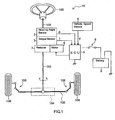
- Fig. 1 is a schematic view of an electric power steering apparatus 10 according to an embodiment of the present invention with associated parts.
- the electric power steering apparatus 10 includes a steering shaft 102, a rack-and-pinion mechanism 104, a steering angle sensor 2, a torque sensor 3, a brushless motor 6, a reducer 7 and an ECU (electronic control unit) 5.
- One end of the steering shaft 102 is connected to a handle (a steering wheel) 100 serving as a steering device for steering, and the other end of the steering shaft 102 is coupled with the rack-and-pinion mechanism 104.
- the steering angle sensor 2 is provided for detecting steering angle indicating rotating position of the handle 100.
- the torque sensor 3 is provided for detecting steering torque applied to the steering shaft 102 by operation of the handle 100.
- the brushless motor 6 is configured to generate steering assist force for lowering driver's burden to operate the handle 100, i.e. driver's burden for the steering operation.
- the reducer 7 transmits the steering assist force from the motor 6 to the steering shaft 102.
- the ECU 5 receives electric power from a battery 8 through an ignition switch 9, and controls the driving of the motor 6 based on sensor signals from the steering angle sensor 2, the torque sensor 3, a vehicle speed sensor 4 and the like.
- the steering torque and the steering angle are respectively detected by the torque sensor 3 and the steering angle sensor in response to the operation of the handle 100 by the driver.
- the motor 6 is driven by the ECU 5 in accordance with the detected steering torque and steering angle as well as vehicle speed detected by the vehicle speed sensor 4.
- the motor 6 then generates the steering assist force, which is applied to the steering shaft 102 through the reducer 7, whereby the driver's burden of steering operation is lowered.
- sum (resultant torque) of the steering torque by the driver's steering operation and torque derived from the steering assist force generated by the motor 6 is applied to the rack-and-pinion mechanism 104 as an output torque via the steering shaft 102 so as to rotate a pinion shaft (not shown).
- connection members 106 are configured by a tie rod and a knuckle arm.
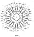
- Fig. 2 is a sectional view of the brushless motor 6 in the embodiment taken perpendicular to a rotation axis of the same.
- the motor 6 includes a rotor 65 rotating together with a motor shaft 66, which corresponds to the rotation axis of the motor6, and an annular stator 61 surrounding the rotor 65 with interposing certain clearance (air gap) therebetween.
- the stator 61 includes a cylindrical yoke 615 and twelve teeth (poles) 611A to 611 L protruding from an inner circumference surface of the yoke 615 toward the motor shaft 66. Coils 612A to 612L are wound around the corresponding teeth 611A to 611L. In response to the application of electric current to the coils 621 A to 612L, the teeth 611A to 611L of the stator 61 function as twelve poles, which are provided in the circumferential direction at even interval.
- the coils 612A to 612L are divided in to three groups, each of which consists of four coils.
- the coils 612A to 612L are so connected to three phase electric power source or drive circuit that one group of coils is driven by U-phase current, another group of coils is driven by V-phase current and the other group of coils is driven by W-phase current.
- Such connection is achieved by employing Y-connection, for example.
- the three phase electric power source or drive circuit controls the rotation of the motor 6 by outputting PWM (pulse width modulation) signals, which are electric voltage signals corresponding to respective phases and controlled in width of pulse.
- PWM pulse width modulation
- the permanent magnets 651A to 651J are, for example, rare metal neodymium (Nd) permanent magnets, which are magnetized in radial direction (the direction perpendicular to the rotation axis of the rotor 65) and are disposed so that the N-poles and S-poles are alternately arranged in the circumferential direction.
- Nd rare metal neodymium
- the motor 6 of this embodiment is a 10poles-12slots type electric motor.
- the stator 61 includes twelve teeth and the permanent magnets 651A to 651J form ten magnetic poles.
- Fig. 3 is an enlarged sectional view of a principal part of the yoke 615 and teeth 611 in the brushless motor 6.
- the coil 612A is wound around the tooth 611A, for example.
- the coil 612A is wound around a cylindrical bobbin 69 having a guard portion at one axial end thereof and then a regulating plate is press fitted at the other axial end of the bobbin 69.
- the bobbin 69 with the coil 612A is externally fitted onto the outer periphery of the tooth 611A, whereby the state in which the coil 612A is wound around the tooth 611A is attained.
- the coils 612A to 612L are wound around the teeth 611 A to 611 L, respectively.
- the aforementioned winding way may be called as concentrated winding or pole winding.
- a portion of Coil that does not form effective magnetic flux is sufficiently eliminated by adopting the concentrated winding in comparison with adopting distributed winding, in which the coil of certain phase is wound around multiple teeth with distributed.
- the concentrated winding a copper loss is suppressed, thereby acquiring a brushless motor of high output power capable of being incorporated in the electric power steering apparatus.
- each of the teeth 611A to 611 L has two tip portions protruding toward the circumferentially opposing direction from an inner end of tooth which faces with the rotor 65.
- tooth width Wt distance between two opposing surfaces of the each of teeth 611A to 611L
- thickness of the tip portion at the circumferential end thereof is tip width Ws
- distance between the tip and the rotor 65 is air gap Wa
- thickness (width) of the yoke 615 in the radial direction is yoke width Wy
- preferable calculation method of tooth width Wt for restraining the cogging torque will be described as follows.
- outer diameter of the stator 61 is 80 mm (millimeter)
- outer diameter of the rotor 65 is 50 mm
- length (thickness) of each of the permanent magnets 651 A to 651 J in radial direction is 3 mm
- the air gap Wa is 0.5 mm
- phase resistance is set to be equal to or less than 25 m ⁇ .
- the tip width Ws may be set about 2.5 mm for trouble-free operation of the motor 6, but it is preferable to set the tip width Ws about 0.5 mm.
- the tip width Ws is set to relatively large value around 0.5 mm or greater, the magnitude and fluctuation range of the cogging torque are suppressed to be smaller than the case in which the tip width Ws is set relatively small value such as 0.25 mm or the vicinity thereof.
- Fig. 4 is a graph showing property of the cogging torque in case that the tooth width Wt is varied from 5 mm to 8 mm.
- These values of the cogging torque are obtained as the result of the known simulation method. Therefore, such result is obtained by inputting the necessary values into a commercially available simulation software.
- the yoke width Wy and the tooth width Wt are set to the same value because the value of output torque is affected by the ratio between the yoke width Wy and the tooth width Wt as mentioned later.
- the yoke width Wy is set to be the same as the tooth width Wt, which varies as mentioned above.
- the cogging torque indicates the smallest value when the tooth width Wt is se about 6.5 mm.
- This setting value (6.5 mm) is approximately same as the value that is obtained by dividing the outer diameter (50 mm) of the rotor 65 by the slot number (12) and multiplying the result of the dividing by ⁇ /2.
- the tooth width Wt and the distance between adjacent two teeth in the teeth 611A to 611L are substantially same at the region where they are approximately tangent to the outer circumference of the rotor 65.
- the distance between the adjacent two teeth is the width of air gap formed between the adjacent two teeth with omitting the tip portions. The distance is referred to as tooth-to-tooth air gap width.
- the sum of the teeth width Wt and the tooth-to-tooth air gaps width in full circle (the sum considering the slot number, i.e. 12) is slightly larger than the outer circumferential length of the rotor 65.
- the tooth width Wt corresponding to the smallest cogging torque is slightly larger than the value obtained by dividing the outer diameter of the rotor 65 by the slot number (12) and multiplying the result of the dividing by ⁇ /2.
- One of the twelve teeth 611 A to 611 L approaches to one of the ten permanent magnets 651A to 651J once in the single rotation of the rotor 65.
- one (e.g. the tooth 611A) of teeth and one (e.g. the permanent magnet 651A) of permanent magnets approaching each other when the center of the tooth 611A corresponds to the center of the permanent magnet 651A in the circumferential direction, the magnetic flux from the permanent magnet 651A is smoothly transmitted to the tooth 611A.
- the relationship only between the tooth 611A and the permanent magnet 651A is focused, magnetic attraction force between them becomes largest and torque becomes smallest.
- the one tooth magnetically apart from the one certain permanent magnet at maximum distance that is, when the middle (center) of the air gap between the tooth 611A and adjacent tooth (e.g. the tooth 611B) corresponds to the center of the permanent magnet 651A in the circumferential direction, the magnetic flux from the permanent magnet 651A is most hardly to be transmitted to the tooth 611A.
- the relationship only between the tooth 611A and the permanent magnet 651 A is focused, the magnetic attraction force between them becomes smallest and the torque becomes largest.
- the state is always (alternatively) established in which centers of five (i.e. half of the total number) permanent magnets among the ten permanent magnets 651 A to 651J locate at the centers of the corresponding teeth 611A to 611 L and in which centers of the other five (remaining half) permanent magnets locate the centers of the corresponding tooth-to-tooth air gap between the adjacent two teeth. Accordingly, even if the torque (the magnetic attraction force) generated between each of the permanent magnets and corresponding tooth varies, the sum of torque generated by the permanent magnets 651A to 651J is small in its change. In view of this, the cogging torque is hardly to be generated or does not become large with the configuration of the embodiment.
- the cogging torque become smallest in case that the tooth width Wt is approximately equal to the tooth-to-tooth air gap width. Further, as shown in Fig. 4, the cogging torque is suppressed in case that the tooth width Wt is set to greater than the tooth-to-tooth air gap width in comparison to the case that the same is set to smaller than the tooth-to-tooth air gap width.
- the reason is as follows.
- the tooth width Wt is greater than the tooth-to-tooth air gap width, the condition in which the magnetic flux from the permanent magnet is smoothly transmitted to the tooth continues for long period, whereby the cogging torque does not become large.
- the tooth width Wt is smaller than the tooth-to-tooth air gap width, the condition in which the magnetic flux from the permanent magnet is smoothly transmitted to the tooth is maintained only for short period, whereby the cogging torque relatively tends to become large.
- Fig. 5 is a graph showing property of the output torque rate in case that the ratio of the yoke width Wy with respect to the tooth width Wt is varied.
- the output torque rate represents the ratio of the output torque with respect to maximum output torque.
- the output torque rate indicates 100% when the ratio of the yoke width Wy relative to the tooth width Wt is approximately 100 %, and the output torque rate shows about 98% when the ratio is approximately 45%. Accordingly, the deterioration of the output torque rate can be omitted in the range that the ratio of the yoke width Wy with respect to the tooth width Wt is not less than 45%. However, if the ratio become smaller than 45% or further, the output torque rate is considerably deteriorated. Thus, in order to prevent the output torque of the motor 6 from deteriorating, it is preferable to set the ratio of the yoke width Wy with respect to the teeth with Wt to be greater than the proximity of 45%. In other words, the yoke width Wy is preferable to be equal to or greater than 45% of the tooth width Wt.
- the brushless motor with the suppressed cogging torque and the electric power steering apparatus incorporating such motor can be provided.
- the brushless motor 6 of the embodiment is 10poles-12slots type and, as shown in Fig. 5, it is preferable to set the ratio of the yoke width Wy relative to the tooth width Wt to be equal to or around 45%. This tendency is widely applicable to the brushless motor whose slot number is greater than the pole number. With reference to Fig. 6, additional explanations will be made.
- Fig. 6 is a graph showing property of the output torque rate in case that the ratio of the yoke width Wy with respect to tooth width Wt is varied in an 8poles-9slots type brushless motor.
- the output torque rate indicates 100% when the ratio of the yoke width Wy relative to the tooth width Wt is approximately 100% and the output torque rate shows about 99% when the ratio of the yoke width Wy relative to the tooth width Wt is approximately 45%. Accordingly, the deterioration of the output torque rate can be omitted in the range that the rate of the yoke width Wy relative to the tooth width Wt is not less than 45%. However, if the ratio becomes smaller than 45% or further, the output torque rate is considerably deteriorated.
- Fig. 7 is a graph showing property of the output torque rate in case ratio of the yoke width Wy with respect to the tooth width Wt is varied in a 14poles-12slots type brushless motor.
- the output torque rate indicates 100% when the ratio of the yoke width Wy relative to the tooth width Wt is approximately 100%, and the output torque rate shows about 98% when the ratio is approximately 35%. Accordingly, the deterioration of the output torque rate can be omitted in the range where the ratio of the yoke width Wy with respect to the tooth width Wt is not less than 35%. However, the ratio decreases to be smaller than this value (35%), the output torque rate considerably decreases as the ratio decreases.
- the ratio of the yoke width Wy relative to the tooth width Wt is set to be greater than the proximity of 35%.
- the yoke width Wy is preferable to be equal to or greater than 35% of the tooth width Wt.
- Fig. 8 is a graph showing property of the output torque rate in case ratio of the yoke width Wy with respect to the tooth width Wt is varied in a 10poles-9slots type brushless motor.
- the output torque rate indicates 100% when the ratio of the yoke width Wy relative to the tooth width Wt is approximately 100%, and the output torque rate shows about 98.4% when the ratio is approximately 35%. Accordingly, the deterioration of the output torque rate can be omitted in the range where the ratio of the yoke width Wy with respect to the tooth width Wt is not less than 35%.
- the output torque rate indicates about 98% when the ratio is approximately 32%, whereby deterioration of the output torque rate can be still omitted until the ratio decrease to reach about 32%.
- the ratio decreases to be smaller than this value (35%, or 32%), the output torque rate considerably decreases as the ratio decreases.
- the yoke width Wy is preferable to be equal to or greater than 35% of the tooth width Wt or is equal to or greater than 32%.
- the ratio of the yoke width Wy relative to the tooth width Wt which is preferable for suppressing the deterioration of the torque is about 35% or greater.
- the motor 6 in the aforementioned embodiment is the 10poles-12slots type brushless motor
- the pole number and the slot number of the motor is not limited to these numbers.
- the brushless motors of 14poles-15slots type, 20poles-21 slots type and other type are applicable.
- the outer diameter of the stator 61 is 80 mm (millimeter), the outer diameter of the rotor 65 is 50 mm, and the length (thickness) of each of the permanent magnets 651A to 65 1J is 3 mm.
- the cogging torque and the output torque rate shown in Figs. 4 to 6 can be obtained in the motor designed so that the outer diameter of the stator is set to be 75 mm to 85 mm, the outer diameter of the rotor is set to be 45 mm to 50 mm, and the length (thickness) of each of the permanent magnet is set to be 2.5 mm to 3.5 mm. Further, similar advantages can be obtained the respective values are set to the vicinity of the above values.
- the width of each of the teeth in the circumferential direction can be set to be greater than or at a vicinity of the value which is obtained by dividing outer diameter of the rotor by the number of the teeth and multiplying the result of dividing by ⁇ /2. Accordingly, the width of each of the teeth in the circumferential direction is set to be greater than the proximity of the distance (air gap) between adjacent two teeth, whereby the cogging torque is efficiently suppressed.
- the width of each of the teeth in the circumferential direction can be set to be greater than or at a vicinity of the value which is obtained by dividing outer diameter of the rotor by the number of the teeth and multiplying the result of dividing by ⁇ /2. Accordingly, the width of each of the teeth in the circumferential direction is set to the proximity of the distance (air gap) between adjacent two teeth, whereby the cogging torque is further efficiently suppressed.
- the thickness of the yoke in radial direction can be equal to or greater than 45% of width of one of the teeth in the circumferential direction.
- a brushless motor includes an annular stator and a rotor which has a plurality of permanent magnets alternately arranged in circumferential direction on the rotor to form poles and which is disposed within the stator to be rotatable with respect to the stator.
- the stator includes a cylindrical yoke and a plurality of teeth which are same in size one another, are connected to the yoke to extend therefrom toward the rotor, and are disposed at even interval in the circumferential direction. Width of each of the teeth in the circumferential direction is set to be greater than or at a vicinity of the value which is obtained by dividing outer diameter of the rotor by the number of the teeth and multiplying the result of dividing by ⁇ /2.
Applications Claiming Priority (1)
| Application Number | Priority Date | Filing Date | Title |
|---|---|---|---|
| JP2006260023A JP2008086064A (ja) | 2006-09-26 | 2006-09-26 | ブラシレスモータ |
Publications (1)
| Publication Number | Publication Date |
|---|---|
| EP1906510A2 true EP1906510A2 (fr) | 2008-04-02 |
Family
ID=38686823
Family Applications (1)
| Application Number | Title | Priority Date | Filing Date |
|---|---|---|---|
| EP07117175A Withdrawn EP1906510A2 (fr) | 2006-09-26 | 2007-09-25 | Moteur sans balai et appareil à direction assistée électrique le comprenant |
Country Status (4)
| Country | Link |
|---|---|
| US (1) | US7595577B2 (fr) |
| EP (1) | EP1906510A2 (fr) |
| JP (1) | JP2008086064A (fr) |
| CN (1) | CN101154839A (fr) |
Cited By (2)
| Publication number | Priority date | Publication date | Assignee | Title |
|---|---|---|---|---|
| EP3214731A4 (fr) * | 2014-10-28 | 2017-09-06 | Panasonic Intellectual Property Management Co., Ltd. | Moteur sans balais et outil électrique |
| CN111279583A (zh) * | 2017-10-19 | 2020-06-12 | 三菱电机株式会社 | 马达、送风机、电动吸尘器以及干手装置 |
Families Citing this family (20)
| Publication number | Priority date | Publication date | Assignee | Title |
|---|---|---|---|---|
| JP2009033927A (ja) * | 2007-07-30 | 2009-02-12 | Jtekt Corp | ブラシレスモータ |
| JP5193548B2 (ja) * | 2007-10-02 | 2013-05-08 | 日立アプライアンス株式会社 | 洗濯乾燥機のファン駆動用永久磁石式回転電機 |
| JP5547924B2 (ja) * | 2008-09-16 | 2014-07-16 | アスモ株式会社 | ブラシレスモータ |
| BRPI0922108A2 (pt) * | 2008-11-07 | 2016-06-21 | Stt Technologies Inc A Joint Venture Of Magna Powertrain Inc And Shw Gmbh | bomba elétrica submersível |
| JP5496690B2 (ja) * | 2010-01-08 | 2014-05-21 | Dmg森精機株式会社 | 回転角度位置決め装置 |
| CN102377257B (zh) * | 2010-08-10 | 2016-03-30 | 德昌电机(深圳)有限公司 | 无刷电机 |
| US9608493B2 (en) | 2010-09-22 | 2017-03-28 | Mitsubishi Electric Corporation | Rotary electric machine and method of manufacturing the same |
| CN101976929B (zh) * | 2010-11-11 | 2012-11-14 | 沈阳工业大学 | 混合磁路永磁直线发电机 |
| US20130038162A1 (en) * | 2011-08-11 | 2013-02-14 | Zhongshan Broad-Ocean Motor Manufacturing Co., Ltd | Motor |
| JP5861394B2 (ja) * | 2011-11-02 | 2016-02-16 | スズキ株式会社 | 電動回転機 |
| JP6095267B2 (ja) * | 2012-02-24 | 2017-03-15 | 株式会社クリーンクラフト | 三相永久磁石式同期モータ |
| FR2994353B1 (fr) | 2012-08-01 | 2014-08-08 | Moving Magnet Tech | Moteur electrique optimise a dents etroites |
| JP2014107993A (ja) * | 2012-11-29 | 2014-06-09 | Hitachi Automotive Systems Ltd | 電動アクチュエータ |
| JP6220662B2 (ja) * | 2013-01-11 | 2017-10-25 | アスモ株式会社 | ブラシレスモータ |
| WO2015186455A1 (fr) * | 2014-06-06 | 2015-12-10 | 三菱電機株式会社 | Moteur à aimants permanents, et moteur à aimants permanents à entraînement intégré |
| JP2017022892A (ja) * | 2015-07-13 | 2017-01-26 | 日本電産サンキョー株式会社 | モータ、モータ装置および指針式表示装置 |
| US10270305B2 (en) | 2015-12-07 | 2019-04-23 | Hamilton Sundstrand Corporation | Motor-generator with multiple stator windings |
| US10381886B2 (en) * | 2016-08-01 | 2019-08-13 | Hamilton Sundstrand Corporation | Motor-generator with radial-flux double-sided stator |
| CN110768422B (zh) * | 2018-07-27 | 2022-03-01 | 广东美芝制冷设备有限公司 | 永磁电机和具有其的压缩机 |
| JP7082301B2 (ja) | 2020-09-30 | 2022-06-08 | ダイキン工業株式会社 | モータ |
Family Cites Families (4)
| Publication number | Priority date | Publication date | Assignee | Title |
|---|---|---|---|---|
| US4801832A (en) * | 1987-11-04 | 1989-01-31 | General Electric Company | Stator and rotor lamination construction for a dynamo-electric machine |
| JP2001275325A (ja) | 2000-03-27 | 2001-10-05 | Honda Motor Co Ltd | 電動パワーステアリング装置 |
| US6822364B2 (en) * | 2002-07-30 | 2004-11-23 | Asmo Co., Ltd. | Brushless motor |
| JP4471752B2 (ja) * | 2004-07-06 | 2010-06-02 | 日立オートモティブシステムズ株式会社 | 電動パワーステアリング用制御装置および電動パワーステアリングシステム |
-
2006
- 2006-09-26 JP JP2006260023A patent/JP2008086064A/ja active Pending
-
2007
- 2007-09-25 EP EP07117175A patent/EP1906510A2/fr not_active Withdrawn
- 2007-09-26 CN CNA2007101626101A patent/CN101154839A/zh active Pending
- 2007-09-26 US US11/861,752 patent/US7595577B2/en not_active Expired - Fee Related
Cited By (4)
| Publication number | Priority date | Publication date | Assignee | Title |
|---|---|---|---|---|
| EP3214731A4 (fr) * | 2014-10-28 | 2017-09-06 | Panasonic Intellectual Property Management Co., Ltd. | Moteur sans balais et outil électrique |
| US10355538B2 (en) | 2014-10-28 | 2019-07-16 | Panasonic Intellectual Property Management Co., Ltd. | Brushless motor and electrically powered tool |
| CN111279583A (zh) * | 2017-10-19 | 2020-06-12 | 三菱电机株式会社 | 马达、送风机、电动吸尘器以及干手装置 |
| CN111279583B (zh) * | 2017-10-19 | 2023-08-08 | 三菱电机株式会社 | 马达、送风机、电动吸尘器以及干手装置 |
Also Published As
| Publication number | Publication date |
|---|---|
| US20080073995A1 (en) | 2008-03-27 |
| US7595577B2 (en) | 2009-09-29 |
| CN101154839A (zh) | 2008-04-02 |
| JP2008086064A (ja) | 2008-04-10 |
Similar Documents
| Publication | Publication Date | Title |
|---|---|---|
| US7595577B2 (en) | Brushless motor and electric power steering apparatus incorporating the same | |
| JP4422567B2 (ja) | モータ駆動装置,電動アクチュエータおよび電動パワーステアリング装置 | |
| JP6411833B2 (ja) | ブラシレスモータ | |
| JP3982739B2 (ja) | 電動パワーステアリング装置 | |
| US9705443B2 (en) | Motor, electric power steering device, and vehicle | |
| US9694845B2 (en) | Motor control device, electric power steering device, and vehicle | |
| WO2008066061A1 (fr) | Moteur sans balai | |
| EP1511155A1 (fr) | Moteur électrique et système de direction utilisant ce moteur | |
| EP2696485A2 (fr) | Machine électrique rotative | |
| EP1971010B1 (fr) | Moteur sans balai et dispositif à direction assistée électrique le comprenant | |
| US20100270100A1 (en) | Electric Power Steering Device | |
| EP1722456A1 (fr) | Rotor pour moteur sans balais | |
| US8049449B2 (en) | Brushless motor control method and brushless motor | |
| EP1713171A1 (fr) | Vehicule electrique | |
| JP3889305B2 (ja) | ブラシレスモータ及びブラシレスモータを搭載した電動パワーステアリング装置 | |
| JP2006197786A (ja) | ブラシレスモータ | |
| JP2016178863A (ja) | 車両用ブラシレスモータ | |
| JP2005045916A (ja) | ステアリング装置 | |
| JP6838840B2 (ja) | ブラシレスモータ及び電動パワーステアリング装置用モータ | |
| EP2256903A2 (fr) | Procédé de fabrication d'un aimant torique, aimant torique et servodirection | |
| US6847177B1 (en) | Apparatus and method for determining rotor lamination shifts in an electric motor | |
| JP2004023905A (ja) | ブラシレスモータ | |
| US20020135253A1 (en) | Rotor assembly for variable torque constant brushless motors | |
| JP2008295207A (ja) | リング磁石、モータ及び電動パワーステアリング装置 | |
| JP2018088814A (ja) | 車両用ブラシレスモータ |
Legal Events
| Date | Code | Title | Description |
|---|---|---|---|
| PUAI | Public reference made under article 153(3) epc to a published international application that has entered the european phase |
Free format text: ORIGINAL CODE: 0009012 |
|
| AK | Designated contracting states |
Kind code of ref document: A2 Designated state(s): AT BE BG CH CY CZ DE DK EE ES FI FR GB GR HU IE IS IT LI LT LU LV MC MT NL PL PT RO SE SI SK TR |
|
| AX | Request for extension of the european patent |
Extension state: AL BA HR MK YU |
|
| STAA | Information on the status of an ep patent application or granted ep patent |
Free format text: STATUS: THE APPLICATION IS DEEMED TO BE WITHDRAWN |
|
| 18D | Application deemed to be withdrawn |
Effective date: 20120403 |