EP1906262A2 - Bilderzeugungsvorrichtung - Google Patents
Bilderzeugungsvorrichtung Download PDFInfo
- Publication number
- EP1906262A2 EP1906262A2 EP07117352A EP07117352A EP1906262A2 EP 1906262 A2 EP1906262 A2 EP 1906262A2 EP 07117352 A EP07117352 A EP 07117352A EP 07117352 A EP07117352 A EP 07117352A EP 1906262 A2 EP1906262 A2 EP 1906262A2
- Authority
- EP
- European Patent Office
- Prior art keywords
- image
- toners
- toner
- toner image
- sheet
- Prior art date
- Legal status (The legal status is an assumption and is not a legal conclusion. Google has not performed a legal analysis and makes no representation as to the accuracy of the status listed.)
- Withdrawn
Links
Images


Classifications
-
- G—PHYSICS
- G03—PHOTOGRAPHY; CINEMATOGRAPHY; ANALOGOUS TECHNIQUES USING WAVES OTHER THAN OPTICAL WAVES; ELECTROGRAPHY; HOLOGRAPHY
- G03G—ELECTROGRAPHY; ELECTROPHOTOGRAPHY; MAGNETOGRAPHY
- G03G15/00—Apparatus for electrographic processes using a charge pattern
-
- H—ELECTRICITY
- H04—ELECTRIC COMMUNICATION TECHNIQUE
- H04N—PICTORIAL COMMUNICATION, e.g. TELEVISION
- H04N1/00—Scanning, transmission or reproduction of documents or the like, e.g. facsimile transmission; Details thereof
- H04N1/23—Reproducing arrangements
- H04N1/2307—Circuits or arrangements for the control thereof, e.g. using a programmed control device, according to a measured quantity
- H04N1/2323—Circuits or arrangements for the control thereof, e.g. using a programmed control device, according to a measured quantity according to characteristics of the reproducing medium, e.g. type, size or availability
-
- G—PHYSICS
- G03—PHOTOGRAPHY; CINEMATOGRAPHY; ANALOGOUS TECHNIQUES USING WAVES OTHER THAN OPTICAL WAVES; ELECTROGRAPHY; HOLOGRAPHY
- G03G—ELECTROGRAPHY; ELECTROPHOTOGRAPHY; MAGNETOGRAPHY
- G03G15/00—Apparatus for electrographic processes using a charge pattern
- G03G15/01—Apparatus for electrographic processes using a charge pattern for producing multicoloured copies
- G03G15/0105—Details of unit
- G03G15/0126—Details of unit using a solid developer
-
- G—PHYSICS
- G03—PHOTOGRAPHY; CINEMATOGRAPHY; ANALOGOUS TECHNIQUES USING WAVES OTHER THAN OPTICAL WAVES; ELECTROGRAPHY; HOLOGRAPHY
- G03G—ELECTROGRAPHY; ELECTROPHOTOGRAPHY; MAGNETOGRAPHY
- G03G15/00—Apparatus for electrographic processes using a charge pattern
- G03G15/06—Apparatus for electrographic processes using a charge pattern for developing
- G03G15/08—Apparatus for electrographic processes using a charge pattern for developing using a solid developer, e.g. powder developer
-
- G—PHYSICS
- G03—PHOTOGRAPHY; CINEMATOGRAPHY; ANALOGOUS TECHNIQUES USING WAVES OTHER THAN OPTICAL WAVES; ELECTROGRAPHY; HOLOGRAPHY
- G03G—ELECTROGRAPHY; ELECTROPHOTOGRAPHY; MAGNETOGRAPHY
- G03G15/00—Apparatus for electrographic processes using a charge pattern
- G03G15/50—Machine control of apparatus for electrographic processes using a charge pattern, e.g. regulating differents parts of the machine, multimode copiers, microprocessor control
- G03G15/5029—Machine control of apparatus for electrographic processes using a charge pattern, e.g. regulating differents parts of the machine, multimode copiers, microprocessor control by measuring the copy material characteristics, e.g. weight, thickness
-
- G—PHYSICS
- G03—PHOTOGRAPHY; CINEMATOGRAPHY; ANALOGOUS TECHNIQUES USING WAVES OTHER THAN OPTICAL WAVES; ELECTROGRAPHY; HOLOGRAPHY
- G03G—ELECTROGRAPHY; ELECTROPHOTOGRAPHY; MAGNETOGRAPHY
- G03G9/00—Developers
- G03G9/08—Developers with toner particles
- G03G9/0821—Developers with toner particles characterised by physical parameters
- G03G9/0823—Electric parameters
-
- G—PHYSICS
- G03—PHOTOGRAPHY; CINEMATOGRAPHY; ANALOGOUS TECHNIQUES USING WAVES OTHER THAN OPTICAL WAVES; ELECTROGRAPHY; HOLOGRAPHY
- G03G—ELECTROGRAPHY; ELECTROPHOTOGRAPHY; MAGNETOGRAPHY
- G03G9/00—Developers
- G03G9/08—Developers with toner particles
- G03G9/09—Colouring agents for toner particles
- G03G9/0926—Colouring agents for toner particles characterised by physical or chemical properties
-
- H—ELECTRICITY
- H04—ELECTRIC COMMUNICATION TECHNIQUE
- H04N—PICTORIAL COMMUNICATION, e.g. TELEVISION
- H04N1/00—Scanning, transmission or reproduction of documents or the like, e.g. facsimile transmission; Details thereof
- H04N1/23—Reproducing arrangements
- H04N1/29—Reproducing arrangements involving production of an electrostatic intermediate picture
- H04N1/295—Circuits or arrangements for the control thereof, e.g. using a programmed control device, according to a measured quantity
-
- G—PHYSICS
- G03—PHOTOGRAPHY; CINEMATOGRAPHY; ANALOGOUS TECHNIQUES USING WAVES OTHER THAN OPTICAL WAVES; ELECTROGRAPHY; HOLOGRAPHY
- G03G—ELECTROGRAPHY; ELECTROPHOTOGRAPHY; MAGNETOGRAPHY
- G03G2215/00—Apparatus for electrophotographic processes
- G03G2215/01—Apparatus for electrophotographic processes for producing multicoloured copies
- G03G2215/0103—Plural electrographic recording members
- G03G2215/0119—Linear arrangement adjacent plural transfer points
Definitions
- the present invention relates to an electrographic image forming apparatus (hereinafter, simply called "image forming apparatus), such as a copying machine, a printer, facsimile terminal equipment, and a multifunction printer, which forms images using an electrophotographic system.
- image forming apparatus such as a copying machine, a printer, facsimile terminal equipment, and a multifunction printer, which forms images using an electrophotographic system.
- the present invention relates to an electrophotographic image forming apparatus using dark toners and light toners, which have a same hue, and are different from each other in density.
- the image forming apparatus forming color images forms four color toner images on, for example, an photosensitive drum of an image bearing member, wherein the four colors include Y (yellow), M (magenta), C (cyan), and K (black).
- the above toner images are sequentially superimposed and transferred on, for example, a sheet (transfer material) held on a transfer drum (transfer film).
- an electrostatic latent image of, for example, cyan as a first color is formed on a photosensitive drum, based on input signals including read image information, and then a C toner image obtained by developing the cyan latent image is transferred on the sheet on the transfer drum.
- the above series of transfer processes are sequentially repeated for other three colors of Y toners, M toners, and K toners as a second color, a third color, and a fourth color in this order, thereby a color image is obtained.
- latent images are collected and formed on the drum surface of the photosensitive drum, wherein the drum surface bears dots of a predetermined potential, and a solid portion, a half tone portion, and a line portion are expressed by changing the density of the dots in the image forming apparatus using digital image signals.
- toner particles are hardly placed on the dots, and there is caused a state in which the toner particles deviate from the dots. Thereby, it is difficult to obtain the gradations of a toner image corresponding to the dot density ratio between the black portions and the white portions of a digital latent image.
- resolution is improved by smaller dots in order to improve image quality, it becomes further difficult to reproduce a latent image formed by a collection of microdots.
- the resolution and the gradations in highlight portions are deteriorated to cause a tendency to loose sharpness in the color of the image.
- disturbance of the dots causes a sense of granularity which leads to reduction in the image quality for the highlight portions, and image unevenness by the granularity is an unpredictable unstable element of the image quality.
- an inkjet recording method is a simple system as can be seen in a technology processing dark-colored ink and light-colored ink, which has been disclosed in, for example, Japanese Patent Application Laid-Open No. 58-039468 .
- the inkjet recording method has been supported by use of recent and excellent high-quality specialized-paper and does not cause the above-described problems raised by the electrophotographic system.
- the inkjet recording method has a unique advantage that there is caused no sense of granularity, because the method used dark-colored ink and light-colored ink. As excellent performances are obtained by use of, especially, light-colored ink, an electrophotographic system applying light-colored ink would result in a largely improved system.
- an idea of introducing light-colored toners is effective for solving the problems caused by use of micro toners.
- an image forming apparatus (refer to, for example, Japanese Patent Application Laid-Open Nos. 11-84764 and 2000-305339 ) forming an image by combining a plurality of toners which are different from one another in density, for example, by using light-colored toners (light toners) in the highlight portions, and dark-colored toners (dark toners) in a solid portions.
- an image forming apparatus (refer to, for example, Japanese Patent Application Laid-Open No. 2000-347476 ) in which dark toners and light toners having a maximum reflection density below half of the maximum reflection density of each of the dark toners are combined.
- an image forming apparatus (refer to, for example, Japanese Patent Application Laid-Open No. 2000-231276 ) having a configuration in which dark toners with an image density of 1.0 or more and light toners with an image density less than 1.0 are combined, when toner quantity on a sheet is 0.5 mg/cm 2 .
- an image forming apparatus (refer to, for example, Japanese Patent Application Laid-Open No. 2001-290319 ) in which toners are combined so that a recording density ratio between the dark toner and the light toner is adjusted at 0.2 through 0.5.
- the inkjet recording method has realized a high-level image forming technology by using high-quality specialized paper with excellent printing performances based on stable high-resolution binary recording. It is very difficult to introduce the image forming technology as it is based on the above inkjet recording method into the electrophotographic system which has mainly used plain paper.
- the electrophotographic system has improved density gradations by using a low resolution screen which has been used for printing, in order to reduce performance difference between high quality specialized paper and plain paper. Thereby, problems, such as coarseness and granularity, peculiar to the electrophotographic system may be solved by using light toners in low density portions.
- toner quantity placed in highlight portions is increased as a result of smoothing the highlight portions.
- toner quantity placed in highlight portions is increased as a result of smoothing the highlight portions.
- transfer unevenness of light toners in highlight portions is easily caused in a toner image with an increased quantity of toner.
- the present invention provides an image forming apparatus using dark toners and light toners, which have a same hue, and are different from each other in density, wherein, according to the image forming apparatus, a high-quality image may be formed, independent from the surface roughness of a recording material.
- the present invention in its first aspect provides an exposure apparatus as specified in claims 1 to 5.
- the present invention in its second aspect provides an exposure method as specified in claims 6 and 7.
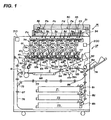
- FIG. 1 is a view showing an image forming apparatus according to an embodiment of the invention
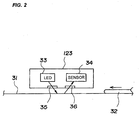
- FIG. 2 is a view showing a structure of an image reading and detecting portion
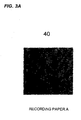
- FIG. 3A is a schematic view showing an image formed on recording paper A as an example of sheet types according to a first embodiment
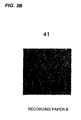
- FIG. 3B is a schematic view showing an image formed on recording paper B as an example of sheet types according to a first embodiment
- FIG. 3C is a schematic view showing an image formed on recording paper C as an example of sheet types according to a first embodiment
- FIG. 4A is a schematic view showing an image formed on the recording paper A after pixel data conversion
- FIG. 4B is a schematic view showing an image formed on the recording paper B after pixel data conversion
- FIG. 4C is a schematic view showing an image formed on the recording paper C after pixel data conversion
- FIG. 5 is a flow diagram showing a series of operations of from image processing to sheet type decision
- FIG. 6 is a schematic view showing thresholds according to which pieces of recording paper A, B, and C are decided;
- FIG. 7 is a functional diagram showing a configuration
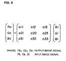
- FIG. 8 is a matrix of basic three elementary colors RGB
- FIG. 9 shows characteristic curves representing recording rates of dark toners and light toners
- FIG. 10 is characteristic curves determining recording rates of dark and light toners
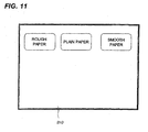
- FIG. 11 is a view showing an operation panel
- FIG. 12A is a view showing image unevenness in a case a processing for reducing a line number is not performed before and after the toner image is transferred from a photosensitive drum to a sheet in a second embodiment according to the invention
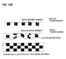
- FIG. 12B is a view showing image unevenness in a case a processing for reducing a line number is not performed before and after the toner image is transferred from the photosensitive drum to a sheet in the second embodiment according to the invention.
- the electrophotographic full-color image forming apparatus has a digital color image reading portion (hereinafter, simply called “reading portion”) 1R in the upper portion, and a digital color image printing portion (hereinafter, simply called “printing portion”) 1P in the lower portion.
- the printing portion 1P may operate based on a read signal output from the reading portion 1R.
- the light of an exposure lamp 32 is applied for exposure scanning to an original 30 mounted on an original base plate glass 31, and a light image reflected from the original 30 is focused onto a full-color CCD sensor 34 through a lens 33 to obtain color-separated color image signals.
- the color-separated color image signals pass through a not-shown amplification circuit for image processing in a video processing means, and are sent to the printing portion 1P through an image memory.
- An image signal from a computer, an image signal based on facsimile communication, and the like are input to the printing portion 1P as well as the read signal of an image which is output from the reading portion 1R are input to the printing portion 1P.
- the printing portion 1P for example, six photosensitive drums 1a through 1f as an image bearing member are supported in the direction of arrows shown in the drawing.
- the six photosensitive drums 1a through 1f are represented by a symbol "1".
- other materials are described with a representative symbol.
- a pre-exposure lamp 11, a corona primary charger 2, a laser exposure optical system 3, a potential sensor 12, six development devices 40 loading toners which are different from one another in spectral characteristics, a transfer device 5A, and a cleaning device 6 are arranged around the photosensitive drum 1. While the above devices form six image forming portions (toner image forming means) Pa through Pf, obviously, the number of the portions is not limited to six but image forming portions of an arbitrary number of four or more may be provided.
- a light-colored magenta (LM) toner is loaded in a development device 41 as one of the six development devices 40 and a light-colored cyan (LC) toner is loaded in a development device 42. Furthermore, there are loaded a yellow (Y) toner in a development device 43, a magenta (M) toner in a development device 44, a cyan (C) toner in a development device 45, and a black (K) toner in a development device 46.
- Y yellow
- M magenta
- C cyan
- K black
- the magenta (M) toner loaded in the development device 44 uses a dark-colored M toner (hereinafter, called “dark toner”) and a light-colored M toner (hereinafter, called “light toner”). Similarly, a dark toner and a light toner are also used for the cyan (C) toner loaded in the development device 45.
- dark toner a dark-colored M toner
- light toner a light-colored M toner
- the dark magenta toner and the light magenta toner are simultaneously used in one image, and the dark magenta toner and the light dark magenta toner are superimposed in the same pixel forming the image. The same holds true for the dark and the light cyan toners.
- an image forming portion having a development device loading toners of metal such as gold and silver, or toners including a fluorescent agent.
- technical ideas of the invention is achieved even when a single-component developing agent including only toners is used, though a two-component developing agent using a combination of toners and carriers is loaded in the development device 40.
- a not-shown laser output portion converts the read image signal output from the reading portion 1R into an optical signal, and laser light converted into the optical signal is reflected on a polygon mirror in the scanner 3 in the laser exposure optical system. Reflected laser light is fully projected onto the drum surfaces of the six photosensitive drums 1 through the lens and the reflection mirrors.
- images are formed as follows in the printing portion 1P.
- the photosensitive drum 1 is rotated in the direction of the arrow, and the photosensitive drum 1 after diselectrification by the pre-exposure lamp 11 is uniformly charged by the primary charger 2 to form an electrostatic latent image on the photosensitive drum 1 by exposure for each of separated colors.
- the development device 40 is operated to develop a latent image on the photosensitive drum 1, and a visible image (toner image) including resins and pigments as a base body is formed on the photosensitive drum 1.
- the toners in the development device 40 are supplied from accommodation portions (hoppers) 60 for each color which are adjacent to the corresponding scanner 3 at any desired timing, so that the toner ratios (or toner quantities) in the development device 40 are kept constant.
- the toner images formed on the photosensitive drums 1 are primarily transferred onto a corresponding intermediate transfer belt 5 as an intermediate transfer body, and each of the toner images are sequentially superimposed on the above transfer belt 5.
- the intermediate transfer belt (the image bearing member, the intermediate transfer body) 5 is wound around a driving roller 51, and driven rollers 52 and 54, and transmits rotary power from a rotary driving source to the driving roller 51.
- the driving roller 51 is rotationally driven to cause rotational travelling of the intermediate transfer belt 5.
- a transfer cleaning device 50 is arranged in a side opposite to the driving roller 51 with the intermediate transfer belt 5 existing therebetween. Moreover, the transfer cleaning device 50 can be contacted with and separated from the driving roller 51.
- the transfer cleaning device 50 is pressed onto the driving roller 51 after superimposing images for required colors on the intermediate transfer belt 5, and then remaining toners on the intermediate transfer belt 5 are cleaned and removed after toner images are transferred onto a sheet as a transfer material (recording material).
- Sheets are conveyed one by one from a storage portion 71, 72, or 73, or a manual paper feed portion 74 through a corresponding one of paper feed means 81 through 84.
- a sheet the skew of which is corrected by a registration roller 85 is sent to a secondary transfer portion T at desired timing, a voltage of positive polarity is applied to a secondary transfer roller (transfer means) 56 from a transfer power supply 561, and a toner image on the intermediate transfer belt 5 is transferred to the sheet.
- the sheet on which the toner image has been transferred in the secondary transfer portion 56 passes through a conveying portion 86, the toner image is fixed on the sheet at a heat-roller fixing device 9, and the sheet is ejected to an output tray or a postprocessing device.
- remaining toners after transferring are cleaned by the transfer cleaning device 50 after secondary transferring, and then the intermediate transfer belt 5 serves for primary transfer processing again in the image forming portions.
- a conveying-path guide 91 is driven just after the sheet passes through the fixing device 9.
- a reversing roller 87 is reversely rotated and the sheet is receded in an opposite direction to the direction the sheet has been sent in a state in which the rear end of the sent sheet is at the head, and then the sheet is sent to a double-sided conveying path 77.
- the sheet passing through the double-sided conveying path 77 undergoes skew correction and timing adjustment by a double-sided conveying roller 88, and is conveyed to the registration roller 85 at desired timing. Subsequently, the above-described image forming process is executed again for image transferring onto one side.
- dark toners and light toners which have a same hue, are prepared for magenta (M) toners and cyan (C) toners.
- Materials which have a same hue means color developing components (pigments) having a same spectral characteristic as one another.
- the word "same” does not always require strict identity, and is generally allowed to include a range within which colors may be regarded as a same color as one another according to a usual concept on, for example, four colors such as Y, M, C, and K.
- toners which are belonging to a same hue and have different densities from one another usually means toners in which color developing components (pigments) included in the toners having resins and the color developing components as a base body are the same as one another in the spectral characteristic and the quantity is different form one another.
- the light toners are defined to belong to a same hue, and to be a toner with relatively low density among a combination of several kinds of toners with different densities from one another.
- light-colored light toners with low density has optical density less than 1.0 after fixing for a toner quantity of 0.5 mg/cm 2 on a sheet.
- dark-colored dark toners with high density has optical density of 1.0 or more after fixing for a toner quantity of 0.5 mg/cm 2 on a sheet.
- the pigment quantity of a dark toner is adjusted so that optical density after fixing is 1.6 at a placed toner quantity of 0.5 mg/cm 2 on a sheet.
- a light toner is designed so that optical density after fixing is 0.8 at a placed toner quantity of 0.5 mg/cm 2
- two kinds of dark toners and light toners are appropriately mixed in quantity for magenta and cyan to obtain important tone reproduction as a target for cyan and magenta.
- a sheet reading and detecting portion (recording material detecting means) 123 is provided in the full-color image forming apparatus according to the present embodiment.
- the sheet reading and detecting portion 123 light is applied onto the surface of a sheet 32 conveyed from a paper cassette 102 by a paper feeding roller 103, and reflected light is focused for image forming to detect a specific area in the sheet 32.
- the sheet reading and detecting portion 123 has an LED 33 as a light applying means, a CMOS sensor 34 as a reading means, lenses 35 and 36 as an image forming means, and the like.
- light emitted from the LED 33 as a light source is applied onto the surface of the sheet conveying guide 31, or the surface of the sheet 32 on the sheet conveying guide 31 through the lens 35.
- Reflected light from the sheet 32 is focused through the lens 36 to form an image in the CMOS sensor 34.
- the image formed above is detected by the CMOS sensor 34 to read the surface of the sheet conveying guide 31 or the sheet 32.
- light from the LED 33 is arranged so that the light is applied at a predetermined angle with respect to the surface of the sheet 32 in a slanting direction.
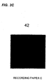
- FIG. 3A through FIG. 3C are views showing an example in which the surfaces of three kinds of sheets 32 (hereinafter, called “recording paper A, B, and C”) are read by the CMOS sensor 34 in the sheet reading and detecting portion 123 to perform digital processing of the output from the CMOS sensor 34 for the surface of each of the recording paper A, B, and C in 8 pixels x 8 pixels.
- the above digital processing is performed by conversion of an analog output from the CMOS sensor 34 into pixel data of eight bits, using a not-shown analog-to-digital converter as a converting means.
- FIG. 3A is a schematic view showing the surface of the recording paper A such as so-called rough paper having relatively coarse cellulose on the sheet surface.
- FIG. 3B is a schematic view showing the surface of the recording paper B such as so-called plain paper which has been usually used.
- FIG. 3C is a schematic view showing the surface of the recording paper C such as smooth paper (gross paper) having fully compressed cellulose.
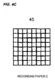
- Pictures 43, 44, and 45 shown in FIG. 4A through FIG. 4C, respectively, are obtained by digital processing of each of the pictures on the corresponding surface read by detection using the CMOS sensor 34.
- the pictures obtained by reading the surfaces are different from one another, depending on the materials and the kinds of the sheets such as the recording paper A, B, and C. Those phenomena are caused by a fact that the cellulose states on the paper surface are different from one another. That is, decision of the surface state of paper cellulose may be made by a picture obtained by digital processing based on detecting by the CMOS sensor 34 for reading.
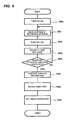
- Reading operation for the surfaces of the recording paper A, B, and C will be described, referring to a flow diagram shown in FIG. 5.
- the CMOS sensor 34 reads the surface at several locations on the sheet 32, that is, the recording paper A, B, and C over several times at steps S50 and S51. Subsequently, constants for gain operation and filter operation in a not-shown filter operation means are adjusted (step S53) after turning off the LED (step S52).
- the gain operation and the filter operation are programmably processed by a control processor.
- the gain operation is performed by adjusting, for example, the gain of an analog output from the CMOS sensor 34. That is, as the surface of a sheet may not be read well when the quantity of light reflected on the sheet surface is too much or too little, the gain is adjusted when a signal change may not be led.
- operations based on, for example, a 1/32 frequency division, a 1/16 frequency division, and a 1/4 frequency division are performed to remove a noise component output from the CMOS sensor 34 when, for example, digital data of 256 gradations by eight bits is obtained after analog to digital conversion of an analog output from the CMOS sensor 34.
- step S54 it is determined (step S54) whether adjustment of the above filter and the above gain has been completed to the extent that it is possible to decide that a sheet is corresponding to which of the recording materials A, B, and C.
- step S55 When it is determined that the adjustment of the filter and the gain is completed to the extent that it is possible to decide the type of the recording material for the sheet (Yes), comparison operation of surface information is performed (step S55). When it is determined that it is not adjusted to the extent that it is possible to decide the type of the recording material for the sheet (No), reading of the surface of the sheet is tried again, returning to the step S51. A sheet kind is decided, based on the result of the above surface-information comparison operation(step S56), and then there is decided an image processing method according to the surface roughness of the sheet (step S57).
- pixel highest density Dmax, and a pixel lowest density Dmin are led from a result obtained by reading the sheet surface at several regions.
- the above operations are executed for each of read regions to perform averaging processing of the obtained pixels.
- a lot of shadows of cellulose are generated when there are coarse paper cellulose on the sheet surface.
- a greater density difference between a bright location and a dark location to make the difference between highest pixel density Dmax and lowest pixel density Dmin greater.
- a difference between Dmax and Dmin becomes smaller because there are a few shadows of cellulose on the surface of a sheet like the recording paper C shown in FIG. 3 and FIG. 4.
- the above-described comparison operation is performed to decide the paper kind, that is, the surface roughness of a sheet.
- FIG. 6 is a schematic view showing a technique for deciding the paper kinds of the recording paper A, B, and C according to subtracted values of Dmax - Dmin.
- thresholds used as a standard for deciding paper kinds for example, X and Y are stored in a nonvolatile memory in a DC controller beforehand.
- the thresholds are not limited to the above two values such as X and Y, and may be set at two or more values.
- the number of sheets, that is, three types of the recording paper A, B, and C are only an example for deciding the paper kind.
- the sheet is decided as the recording paper A when the value of Dmax - Dmin is larger than the threshold Y, that is, Dmax - Dmin > Y.
- the sheet is decided as the recording paper B when the value of Dmax - Dmin is smaller than the threshold Y, and larger than the threshold X, and the sheet is decided as the recording paper C when the value of Dmax - Dmin is smaller than the threshold X.
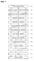
- an image signal output from full-color sensor 100 is input to an analog signal processing portion 101 for adjustment of a gain and an offset.
- the image signals are converted into RGB digital signals of, for example, eight bits (0 through 255 levels: 256 gradations) in an analog to digital converting portion 102 for each of color components.
- a shading correction portion 103 a signal reading a standard white board (not-shown) is used for each color, and gains are optimized, corresponding to each of the CCD sensor cells, for shading correction in order to eliminate dispersions in sensitivity for each of cells in a sensor cell group including arranged CCDs.
- a line delay portion 104 corrects a spatial displacement included in the image signal output from the shading correction portion 103.
- the above spatial displacement is caused because each of the line sensors in the full-color sensor 100 are arranged separated at a predetermined distance from one another in the sub-scanning direction. Specifically, line delay of each of color component signals of R (red) and of G (green) is performed in the sub-scanning direction with reference to a B (blue) color component signal, and the phases of the three color component signals are synchronized.
- An input masking portion 105 converts a color space of the image signal output from the line delay portion 104 into an NTSC standard color space, using a matrix operation expression shown in FIG. 8. That is, the color space of each color component signal output from the full-color sensor 100 is converted into the NTSC standard color space, though the color space of each color component signal is decided by the spectral characteristics of the filters for each color component.
- a lookup table including, for example, ROMs and the like forms a LOG converting portion 106 converting an RGB brightness signal output from the input masking portion 105 into a CMY density signal.
- a line delay memory 107 delays the image signal output from the LOG converting portion 106 by a period (line delay) during which a black character determining portion (not shown) generates a control signal such as UCR, FILTER, and SEN by the output from the input masking portion 105.
- a masking UCR portion 108 extracts a black component signal K from the image signal output from the line delay memory 107. Furthermore, the masking UCR portion 108 performs matrix operation for Y, M, C, and K, wherein color turbidities of the color recording materials in the printing portion are corrected in the portion 108, and color element image signals of, for example, eight bits are output in the order of M, C, Y, and K every reading operations in the reading portion 1R.
- matrix coefficients used for matrix operation are set by a not shown CPU 200.
- a ⁇ correction portion 109 performs density correction of the image signal output from the masking UCR portion 108 in order to match the image signal with an ideal gradation characteristics of the printing portion.
- An output filter (a spatial filter processing portion) 110 performs edge emphasis processing or smoothing processing for the image signal output from the ⁇ correction portion 109, based on the control signal from a CPU.
- An LUT (an adjusting means) 111 matches the density of an original image with that of an output image, and includes, for example, RAM and the like.
- the translation table is set by a CPU.
- a pulse width modulator (PWM) 112 outputs a pulse signal with a pulse width corresponding to the level of the input image signal, and the pulse signal is input to a laser driver 113 driving a semiconductor laser (a laser light source).
- the scanner 3 forms an electrostatic latent image by scanning exposure of the surface of the photosensitive drum 1 by laser light, based on the image signal input from the image reading means 21.
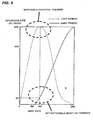
- FIG. 9 shows characteristic curves determining recording rates of dark and light toner for dark toners denoted by a solid-line curve, and light toners denoted by a dashed-line curve.
- a color component image signal Data of eight bits which is data for the cyan component and the magenta component
- recording rates Rn and Rt are decided for dark toners and light toners, respectively. It is possible to interpret that the recording rate represents a quantity of formed dots, a larger rate shows high density, and a smaller rate shows low density.
- a recording rate Rt for light toners is 255/255
- a recording rate Rn for dark toners is 40/255.
- the recording rate is represented by an absolute value, assuming that 255 represents 100 percents.
- the recording rates for the light toners and the dark toners are changed to be adaptable to the recording paper A, as shown in FIG. 10.
- the reason is that, as the paper cellulose on the surface is coarse, and a lot of cellulose shadows are generated in the case of the recording paper A as shown in FIG. 3 and FIG. 4, there is a great difference between the bright locations and the dark locations, and the difference between highest pixel density Dmax and lowest pixel density Dmin becomes larger.
- the recording rates are set at a value between those for the recording paper A and B when it is found from the result of the above-described determination that the sheet 32 is corresponding to the recording paper B.
- a use quantity of dark toners is increased as image data for a toner image to be formed is increased.
- the density of a toner image with the lowest density among toner images formed by using dark toners is changed according to the surface roughness of the sheet. That is, a toner image with the lowest density among toner images formed by using dark toners and light toners is changed by the surface roughness of the sheet.
- dark toners are used for from image data 20 through 255.
- dark toners are used for image data within a range of 50 through 255.
- dark toners are used for image data within a range of 75 through 255.
- the recording rates for light toners and dark toners with regard to magenta and cyan are changed according to kinds such as the surface roughness and the like of the sheet 32 as described above, wherein the surface roughness are represented by the recording paper A, B, and C.
- the surface roughness are represented by the recording paper A, B, and C.
- a pattern generator (not shown) may be installed for registration of gradation patterns, and a signal may be directly transmitted to a pulse width modulator 62.
- the surface roughness of a sheet has been detected by the sheet reading and detecting portion 123.
- the present example has described the device in which, once a toner image formed on the photosensitive drum 1 is transferred onto the intermediate transfer belt, the toner image is transferred onto a sheet.
- the present invention may be also applied to an image forming apparatus in which a toner image formed on the photosensitive drum 1 is transferred directly to a sheet.
- a content ratio between dark toners and light toners is changed according to sheet kinds (surface roughness) in a similar manner to that of the first embodiment, and, furthermore, the resolution in a low density portion is reduced according to sheet kinds (surface roughness) in an image forming apparatus having a similar configuration to that according to the first embodiment.
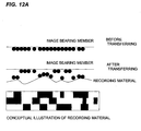
- FIG. 12A and FIG. 12B are a schematic view showing states in which, when sheet paper kinds are expressed by the rugged state of a sheet surface, that is, "surface roughness", transferring of a toner image formed on the image bearing member such as the photosensitive drum 1 onto a sheet is influenced by the surface roughness of a sheet.
- FIG. 12A a toner image before transferring is formed in a uniform thin layer on the image bearing member. But, a well-transferred state is not obtained after transferring because electric discharge is generated in concave portions caused by the surface roughness of the sheet at electrostatic transferring. Thereby, image defectives are caused by transferring unevenness (image unevenness) according to degrees of the surface roughness of the sheet.
- FIG. 12B an image is formed with less influences by the surface roughness of the sheet when a toner image before transferring is concentrated (the number of lines is reduced) in a massive state on the image bearing member. Thereby, there may be reproduced low density portions with regularity schematically expressed in a checkered pattern, and image defectives caused by transferring unevenness are prevented.
- the pulse width modulator (resolution changing means) 112 shown in the block diagram of FIG. 7 changes the number of lines of a toner image of image data 100 or less according to the kinds of a sheet (surface roughness), that is, the resolution in the direction of the rotation axis of the photosensitive drum 1 according to the kinds of a sheet (surface roughness).
- the pulse width modulator (resolution changing means) 112 shown in the block diagram of FIG. 7 changes the number of lines of a toner image of image data 100 or less according to the kinds of a sheet (surface roughness), that is, the resolution in the direction of the rotation axis of the photosensitive drum 1 according to the kinds of a sheet (surface roughness).
- resolution at use of a sheet corresponding to the recording paper A with a rough surface is reduced in comparison with the number of lines (resolution) at use of a sheet corresponding to the recording paper C with a smooth surface).
- the number of lines for an image exceeding image data 100 is 200 regardless of the kind of a sheet.
- An image forming apparatus comprising: an image bearing member; a toner image forming means forming a toner image on the image bearing member, using light toners, and dark toners which have a same hue as that of the light toners and are darker than the light toners; a transfer means which electrostatically transfers a toner image on the image bearing member onto a recording material; and an adjusting means which adjusts the toner image forming means so that a rate between the dark toners and the light toners included in a toner image with predetermined density on the image bearing member is changed according to the roughness of a surface onto which the toner image on the recording member is transferred.
Landscapes
- Physics & Mathematics (AREA)
- General Physics & Mathematics (AREA)
- Engineering & Computer Science (AREA)
- Multimedia (AREA)
- Signal Processing (AREA)
- Microelectronics & Electronic Packaging (AREA)
- Color Electrophotography (AREA)
- Control Or Security For Electrophotography (AREA)
- Electrostatic Charge, Transfer And Separation In Electrography (AREA)
Applications Claiming Priority (1)
| Application Number | Priority Date | Filing Date | Title |
|---|---|---|---|
| JP2006268291 | 2006-09-29 |
Publications (2)
| Publication Number | Publication Date |
|---|---|
| EP1906262A2 true EP1906262A2 (de) | 2008-04-02 |
| EP1906262A3 EP1906262A3 (de) | 2013-11-27 |
Family
ID=38951736
Family Applications (1)
| Application Number | Title | Priority Date | Filing Date |
|---|---|---|---|
| EP07117352.0A Withdrawn EP1906262A3 (de) | 2006-09-29 | 2007-09-27 | Bilderzeugungsvorrichtung |
Country Status (4)
| Country | Link |
|---|---|
| US (1) | US7945177B2 (de) |
| EP (1) | EP1906262A3 (de) |
| KR (1) | KR100905630B1 (de) |
| CN (1) | CN101154068B (de) |
Families Citing this family (6)
| Publication number | Priority date | Publication date | Assignee | Title |
|---|---|---|---|---|
| KR20100046899A (ko) * | 2008-10-28 | 2010-05-07 | 삼성전자주식회사 | 화상형성장치 |
| JP5365212B2 (ja) * | 2009-01-22 | 2013-12-11 | 富士ゼロックス株式会社 | 静電荷像現像用トナーセット、静電荷像現像用現像剤セットおよび画像形成装置 |
| JP2010169842A (ja) * | 2009-01-22 | 2010-08-05 | Fuji Xerox Co Ltd | 静電荷像現像用グリーントナー、静電荷像現像用現像剤、静電荷像現像用トナーセット、静電荷像現像用現像剤セットおよび画像形成装置 |
| JP2017120323A (ja) * | 2015-12-28 | 2017-07-06 | 富士ゼロックス株式会社 | 静電荷像現像用トナー、静電荷像現像剤、トナーカートリッジ、プロセスカートリッジ、画像形成装置、及び画像形成方法 |
| JP6757651B2 (ja) * | 2016-11-21 | 2020-09-23 | 株式会社沖データ | 画像形成装置 |
| JP7283047B2 (ja) * | 2018-10-22 | 2023-05-30 | コニカミノルタ株式会社 | 画像形成方法 |
Family Cites Families (24)
| Publication number | Priority date | Publication date | Assignee | Title |
|---|---|---|---|---|
| JPS5839468A (ja) | 1981-09-04 | 1983-03-08 | Nippon Telegr & Teleph Corp <Ntt> | インクジエツト記録の階調画像記録方式 |
| JPH01184764A (ja) | 1988-01-18 | 1989-07-24 | Nec Corp | 信号記録方式 |
| US5689761A (en) * | 1996-09-26 | 1997-11-18 | Xerox Corporation | Liquid immersion development machine having a development system adapted to compensate for copy paper roughness |
| JP3518257B2 (ja) * | 1997-06-18 | 2004-04-12 | 富士ゼロックス株式会社 | 多色画像形成方法 |
| JP4227695B2 (ja) | 1999-02-09 | 2009-02-18 | 株式会社リコー | 画像形成装置 |
| JP4378026B2 (ja) * | 1999-04-02 | 2009-12-02 | キヤノン株式会社 | 画像形成装置及び画像形成方法 |
| JP2000305339A (ja) | 1999-04-22 | 2000-11-02 | Konica Corp | 画像形成方法、画像形成装置とそれに用いる静電潜像現像用トナー |
| JP2000355443A (ja) | 1999-06-16 | 2000-12-26 | Funai Electric Co Ltd | プリンタシステム |
| JP4217355B2 (ja) * | 1999-09-22 | 2009-01-28 | 東芝テック株式会社 | 画像形成装置 |
| US6498910B2 (en) * | 2000-04-07 | 2002-12-24 | Konica Corporation | Image forming with light and dark hue toners |
| JP2001290319A (ja) | 2000-04-07 | 2001-10-19 | Konica Corp | 画像形成装置 |
| JP4428855B2 (ja) * | 2000-12-12 | 2010-03-10 | キヤノン株式会社 | 画像形成装置 |
| JP2002328486A (ja) | 2001-04-27 | 2002-11-15 | Konica Corp | 画像形成方法 |
| JP4289827B2 (ja) * | 2002-04-12 | 2009-07-01 | キヤノン株式会社 | 画像形成装置 |
| JP4227351B2 (ja) | 2002-04-12 | 2009-02-18 | キヤノン株式会社 | 記録材の種別判別装置および画像形成装置 |
| JP2004212693A (ja) | 2003-01-06 | 2004-07-29 | Canon Inc | 画像形成装置 |
| JP2005022254A (ja) * | 2003-07-02 | 2005-01-27 | Canon Inc | 画像形成装置 |
| JP4681832B2 (ja) | 2003-07-31 | 2011-05-11 | キヤノン株式会社 | 同一色相で濃度の異なる複数のトナーの使用比率を、記録媒体の光沢度に応じて変更する画像形成装置 |
| US7110686B2 (en) * | 2003-07-31 | 2006-09-19 | Canon Kabushiki Kaisha | Image forming apparatus capable of changing usage ratio among multiple toners |
| JP2005049523A (ja) | 2003-07-31 | 2005-02-24 | Canon Inc | 画像形成装置 |
| JP4993653B2 (ja) * | 2003-10-03 | 2012-08-08 | キヤノン株式会社 | 記録材判別装置および画像形成装置並びにその方法 |
| DE602004017562D1 (de) * | 2003-11-19 | 2008-12-18 | Canon Kk | Tonerelemente, Benutzung von Tief-Cyan-Toner und Schwach-Cyan-Toner und Bildaufzeichnungsverfahren |
| JP4642518B2 (ja) * | 2004-03-29 | 2011-03-02 | キヤノン株式会社 | 画像形成装置 |
| US7450866B2 (en) * | 2004-12-09 | 2008-11-11 | Canon Kabushiki Kaisha | Image forming apparatus and method for forming images for carrying out development using a light toner and a dark toner having substantially the same hue |
-
2007
- 2007-09-24 US US11/860,139 patent/US7945177B2/en not_active Expired - Fee Related
- 2007-09-27 EP EP07117352.0A patent/EP1906262A3/de not_active Withdrawn
- 2007-09-28 KR KR1020070098464A patent/KR100905630B1/ko not_active Expired - Fee Related
- 2007-09-29 CN CN2007101620016A patent/CN101154068B/zh not_active Expired - Fee Related
Also Published As
| Publication number | Publication date |
|---|---|
| US20080181647A1 (en) | 2008-07-31 |
| US7945177B2 (en) | 2011-05-17 |
| KR20080029935A (ko) | 2008-04-03 |
| CN101154068A (zh) | 2008-04-02 |
| EP1906262A3 (de) | 2013-11-27 |
| KR100905630B1 (ko) | 2009-06-30 |
| CN101154068B (zh) | 2010-09-01 |
Similar Documents
| Publication | Publication Date | Title |
|---|---|---|
| JP4607723B2 (ja) | 画像形成装置 | |
| US7990589B2 (en) | Image processing apparatus and method therefor | |
| US8218196B2 (en) | Image processing method and image processing apparatus | |
| US20070046961A1 (en) | Image processing apparatus and method therefor | |
| US7945177B2 (en) | Image forming apparatus with first and second settable resolution grades | |
| JP4006411B2 (ja) | 画像形成装置及び方法 | |
| US8599434B2 (en) | Method and system for improved solid area and heavy shadow uniformity in printed documents | |
| JP2006163000A (ja) | 画像形成装置及びその制御方法 | |
| JP2008107803A (ja) | 画像形成装置及び画像形成方法 | |
| JP3723043B2 (ja) | 画像処理装置、画像読取装置および画像形成装置 | |
| US20080187244A1 (en) | Image processing apparatus and image processing method | |
| JP4158345B2 (ja) | 画像処理装置、画像形成装置及び画像処理方法 | |
| US7751086B2 (en) | Image processing apparatus and image processing method for generating image data for forming an image using a plurality of color materials of similar colors and different densities | |
| US7551320B2 (en) | Image processing apparatus, image forming apparatus, control program, and computer-readable recording medium | |
| US6842589B2 (en) | Method and image forming apparatus producing toner pattern without adhesion of toner to separation pick | |
| JP2000287077A (ja) | 網点画像判別方法及び装置 | |
| JP4817663B2 (ja) | 画像形成装置 | |
| JP2005189715A (ja) | 画像形成装置 | |
| JP2872680B2 (ja) | 黒文字の検出方式 | |
| JP4956490B2 (ja) | 画像形成装置 | |
| JP2007158844A (ja) | 画像処理装置 | |
| JP4058795B2 (ja) | 画像処理装置および画像処理の方法 | |
| JP3790877B2 (ja) | 画像処理装置 | |
| JP3762567B2 (ja) | カラー画像形成装置 | |
| JP2006121675A (ja) | 画像処理装置、画像処理プログラム |
Legal Events
| Date | Code | Title | Description |
|---|---|---|---|
| PUAI | Public reference made under article 153(3) epc to a published international application that has entered the european phase |
Free format text: ORIGINAL CODE: 0009012 |
|
| AK | Designated contracting states |
Kind code of ref document: A2 Designated state(s): AT BE BG CH CY CZ DE DK EE ES FI FR GB GR HU IE IS IT LI LT LU LV MC MT NL PL PT RO SE SI SK TR |
|
| AX | Request for extension of the european patent |
Extension state: AL BA HR MK YU |
|
| PUAL | Search report despatched |
Free format text: ORIGINAL CODE: 0009013 |
|
| AK | Designated contracting states |
Kind code of ref document: A3 Designated state(s): AT BE BG CH CY CZ DE DK EE ES FI FR GB GR HU IE IS IT LI LT LU LV MC MT NL PL PT RO SE SI SK TR |
|
| AX | Request for extension of the european patent |
Extension state: AL BA HR MK RS |
|
| RIC1 | Information provided on ipc code assigned before grant |
Ipc: G03G 15/01 20060101ALI20131021BHEP Ipc: G03G 15/00 20060101AFI20131021BHEP |
|
| 17P | Request for examination filed |
Effective date: 20140318 |
|
| RBV | Designated contracting states (corrected) |
Designated state(s): AT BE BG CH CY CZ DE DK EE ES FI FR GB GR HU IE IS IT LI LT LU LV MC MT NL PL PT RO SE SI SK TR |
|
| AKX | Designation fees paid |
Designated state(s): DE FR GB IT |
|
| 17Q | First examination report despatched |
Effective date: 20150115 |
|
| STAA | Information on the status of an ep patent application or granted ep patent |
Free format text: STATUS: THE APPLICATION HAS BEEN WITHDRAWN |
|
| 18W | Application withdrawn |
Effective date: 20150519 |