EP1901895B1 - Verfahren zum einbringen einer verriegelungsnut in eine nutflanke - Google Patents
Verfahren zum einbringen einer verriegelungsnut in eine nutflanke Download PDFInfo
- Publication number
- EP1901895B1 EP1901895B1 EP06754125A EP06754125A EP1901895B1 EP 1901895 B1 EP1901895 B1 EP 1901895B1 EP 06754125 A EP06754125 A EP 06754125A EP 06754125 A EP06754125 A EP 06754125A EP 1901895 B1 EP1901895 B1 EP 1901895B1
- Authority
- EP
- European Patent Office
- Prior art keywords
- groove
- milling head
- locking groove
- holder
- locking
- Prior art date
- Legal status (The legal status is an assumption and is not a legal conclusion. Google has not performed a legal analysis and makes no representation as to the accuracy of the status listed.)
- Active
Links
- 238000000034 method Methods 0.000 title claims abstract description 14
- 238000003754 machining Methods 0.000 title claims abstract description 11
- 238000003801 milling Methods 0.000 claims abstract description 121
- 230000005540 biological transmission Effects 0.000 abstract description 22
- 230000033001 locomotion Effects 0.000 abstract description 5
- 238000003780 insertion Methods 0.000 description 10
- 230000037431 insertion Effects 0.000 description 10
- 238000013461 design Methods 0.000 description 3
- 238000012546 transfer Methods 0.000 description 2
- 238000005520 cutting process Methods 0.000 description 1
- 230000003247 decreasing effect Effects 0.000 description 1
- 238000006073 displacement reaction Methods 0.000 description 1
- 238000004519 manufacturing process Methods 0.000 description 1
- 238000012545 processing Methods 0.000 description 1
- 238000004381 surface treatment Methods 0.000 description 1
- 238000012549 training Methods 0.000 description 1
Images


Classifications
-
- B—PERFORMING OPERATIONS; TRANSPORTING
- B27—WORKING OR PRESERVING WOOD OR SIMILAR MATERIAL; NAILING OR STAPLING MACHINES IN GENERAL
- B27F—DOVETAILED WORK; TENONS; SLOTTING MACHINES FOR WOOD OR SIMILAR MATERIAL; NAILING OR STAPLING MACHINES
- B27F1/00—Dovetailed work; Tenons; Making tongues or grooves; Groove- and- tongue jointed work; Finger- joints
- B27F1/02—Making tongues or grooves, of indefinite length
-
- B—PERFORMING OPERATIONS; TRANSPORTING
- B27—WORKING OR PRESERVING WOOD OR SIMILAR MATERIAL; NAILING OR STAPLING MACHINES IN GENERAL
- B27G—ACCESSORY MACHINES OR APPARATUS FOR WORKING WOOD OR SIMILAR MATERIALS; TOOLS FOR WORKING WOOD OR SIMILAR MATERIALS; SAFETY DEVICES FOR WOOD WORKING MACHINES OR TOOLS
- B27G13/00—Cutter blocks; Other rotary cutting tools
-
- B—PERFORMING OPERATIONS; TRANSPORTING
- B27—WORKING OR PRESERVING WOOD OR SIMILAR MATERIAL; NAILING OR STAPLING MACHINES IN GENERAL
- B27M—WORKING OF WOOD NOT PROVIDED FOR IN SUBCLASSES B27B - B27L; MANUFACTURE OF SPECIFIC WOODEN ARTICLES
- B27M3/00—Manufacture or reconditioning of specific semi-finished or finished articles
- B27M3/04—Manufacture or reconditioning of specific semi-finished or finished articles of flooring elements, e.g. parqueting blocks
-
- E—FIXED CONSTRUCTIONS
- E04—BUILDING
- E04F—FINISHING WORK ON BUILDINGS, e.g. STAIRS, FLOORS
- E04F15/00—Flooring
- E04F15/02—Flooring or floor layers composed of a number of similar elements
- E04F15/02038—Flooring or floor layers composed of a number of similar elements characterised by tongue and groove connections between neighbouring flooring elements
-
- E—FIXED CONSTRUCTIONS
- E04—BUILDING
- E04F—FINISHING WORK ON BUILDINGS, e.g. STAIRS, FLOORS
- E04F2201/00—Joining sheets or plates or panels
- E04F2201/01—Joining sheets, plates or panels with edges in abutting relationship
- E04F2201/0153—Joining sheets, plates or panels with edges in abutting relationship by rotating the sheets, plates or panels around an axis which is parallel to the abutting edges, possibly combined with a sliding movement
-
- Y—GENERAL TAGGING OF NEW TECHNOLOGICAL DEVELOPMENTS; GENERAL TAGGING OF CROSS-SECTIONAL TECHNOLOGIES SPANNING OVER SEVERAL SECTIONS OF THE IPC; TECHNICAL SUBJECTS COVERED BY FORMER USPC CROSS-REFERENCE ART COLLECTIONS [XRACs] AND DIGESTS
- Y10—TECHNICAL SUBJECTS COVERED BY FORMER USPC
- Y10T—TECHNICAL SUBJECTS COVERED BY FORMER US CLASSIFICATION
- Y10T409/00—Gear cutting, milling, or planing
- Y10T409/30—Milling
- Y10T409/30784—Milling including means to adustably position cutter
- Y10T409/307952—Linear adjustment
- Y10T409/308232—Linear adjustment and angular adjustment
Definitions
- the invention relates to a method for introducing a locking groove in a groove flank of a provided in a panel, in particular floor panel, connecting groove, which is part of a tongue and groove connection for connecting adjacent panels, wherein the panel has an upper and a lower side; and the locking groove is provided in the part of the connecting groove which is surrounded on both sides by groove flanks (see eg US-A-2009/0177584 , FIGS. 10a to 10c).
- Locking grooves serve to lock two adjacent laid panels. They serve to receive a correspondingly formed locking element, which is usually on or on one of the two spring sides of a spring, which is integrally formed on the opposite side edge of the panel.
- the insertion of two adjacent panels can be done for example by a pivoting movement and / or by an exclusively horizontal displacement movement.
- the disadvantage is that the use of such planing tools, especially with decreasing sharpness of the planing tool, does not allow the desired accuracy in the processing of the panels and sometimes high holding forces for holding the planing tool are required.
- the object of the invention is therefore to avoid the aforementioned disadvantages and to provide a method that simplifies the introduction of a locking groove in the groove flank.
- the locking groove by means of a rotating milling tool, which includes a drive, a milling head and a rotation of the drive on the milling head transmitting transmission device and a holder for the milling head is introduced, wherein the milling head at least bracket side due to Holder has a deviating from the actual radius R free radius r and the milling head during insertion of the locking groove at least with its entire free radius r, in particular completely, in the part of the connecting groove surrounded on both sides of groove flanks.
- a rotating milling tool which includes a drive, a milling head and a rotation of the drive on the milling head transmitting transmission device and a holder for the milling head is introduced, wherein the milling head at least bracket side due to Holder has a deviating from the actual radius R free radius r and the milling head during insertion of the locking groove at least with its entire free radius r, in particular completely, in the part of the connecting groove surrounded on both sides of groove flanks.
- the free radius r determines the maximum achievable locking groove depth because of the actual radius R, the radius of the holder must be deducted.
- the free radius r is between the axis of rotation of the rotary milling tool and the point of the rotary milling tool that is closest to the groove bottom. If the holder is not designed as a central shaft holding the milling head, a free radius r can result in the case of an out-of-center holder which is greater than the radius R of the milling head.
- the actual distance between the holder-side outer edge of the milling head and the outer edge of the holder, in particular a center of the milling head holding shaft understood.
- this term also includes the corresponding distances between the extended projection of the outer edge of the holder and the outer edge of the milling head at axially spaced from the holder points of the milling head.
- non-cylindrical design of the milling head result in so far different "free radii r" along the axial extent of the milling head.
- the dimensions of the milling head are small, in particular, the diameter of the milling head is small, ie it has a maximum of the total value resulting from the height of the connecting groove and the depth (n) of the locking groove (s), both the height of the connecting groove as well as the depth of the respective locking groove in Direction orthogonal to the axis of rotation of the milling head can be seen.
- the introduction of the locking groove is effected by a relative movement between the panel and the milling head along the side edge into which the locking groove is to be introduced.
- the milling head can alternatively be inserted for lateral insertion into the connecting groove in the direction of the arrow 18 in the connecting groove and then rotated to create the locking groove at this point.
- the holder may be formed by a rigidly shaped transmission device, e.g. be designed as a rigid shaft, so that the transmission device not only transmits the rotary motion to the milling head but also holds the milling head.
- the holder may also be formed as a separate component, in which case the transmission device may be, for example, a toothed belt or a toothed wheel or wheel.
- the free radius r may be greater than the actual radius R of the milling head.
- the locking groove is formed as an open area behind a projecting portion of the groove flank of the connecting groove. It is obvious that the projecting portion of the groove flank does not have to represent the entire remaining groove flank. Thus, seen in the insertion direction in front of the projecting portion, ie in the region of the groove flanks facing away from the connecting groove base, again a recessed part region may be provided.
- the transmission device may for example be designed as a rigid shaft, on the end of the milling head is attached. The end of the shaft opposite the milling head is connected to the drive.
- the milling head is designed in terms of its geometry so that the locking groove can be introduced with the intended contour in the groove flank.
- the general orientation of the transmission device can be parallel as well as at an angle to the top or bottom. This depends on the one hand on the contour of the milling head and the intended contour of the introduced locking groove and on the other hand on the general configuration of the side edge of the panel in question.
- the invention further relates to a method for introducing a locking groove in a groove flank of a provided in a panel, in particular floor panel, connecting groove, which is part of a tongue and groove connection for connecting adjacent panels, wherein the panel has a top and a bottom, and the Locking groove is provided in the part of the connecting groove, which is surrounded on both sides by groove flanks, wherein the groove flanks are of different lengths relative to the groove base, characterized characterized in that the locking groove by means of a rotary milling tool, which includes a drive, a milling head and a rotation of the drive on the milling head transmitting transmission device and a holder for the milling head is introduced, wherein the milling head at least bracket side due to the holder has a free radius r and the milling head during insertion of the locking groove is at least a substantial proportion of its free radius r, in particular completely, in the part of the connecting groove surrounded on both sides by groove flanks, wherein the free radius r is completely between the long groove flank and
- the invention further relates to a method for introducing a locking groove into a groove flank of a connecting groove provided in a panel, in particular a floor panel, which is part of a tongue and groove connection for connecting adjacent panels, the panel having a top and a bottom, and the locking groove is provided in the part of the connecting groove which is surrounded on both sides by groove flanks, the groove flanks differing with respect to the groove base are long, characterized in that the locking groove by means of a rotating milling tool, which includes a drive, a milling head and a rotation of the drive on the milling head transmitting transmission device and a holder for the milling head is introduced, wherein the milling head at least bracket side due to Holder has a free radius r and the milling head during insertion of the locking groove is at least with its free radius r, in particular completely, between the long groove flank and the projection P extended short groove flank.
- a rotating milling tool which includes a drive, a milling head and a rotation of the drive on the milling head transmit
- the axes of rotation of the milling head and the drive can be aligned so that the rotation of the drive takes place about the same axis as that of the milling head.
- the transmission device is designed, for example, as a rigid shaft.
- At least one deflection device in particular an angular gear and / or a flexible shaft, can be provided between the milling head and the transmission device.
- An example of a bevel gear would be a design like a "dentist's drill".
- several deflection can be provided for a multiple deflection.
- the overall height of the milling head and holder can be related to the dimensions of the connecting groove and the locking groove (s), in each case depending on the angle of rotation of the milling head relative to the orientation of the top and bottom of the panel.
- the deflecting device can be at least substantially, in particular completely, in the connecting groove surrounded by the two groove flanks.
- the invention relates to the use of a rotary milling tool, which includes a drive, a milling head and a transmission transmitting the rotation of the drive to the milling head and a holder for the milling head.
- Such milling tools are used, for example, for the surface treatment of metallic workpieces or also of wooden workpieces by means of cutting removal.
- the milling head is rotated by the drive, wherein the surface to be machined of the workpiece is processed depending on the configuration of the milling head with the end face and / or the circumferential side surface of the milling head.
- the axes of rotation of the milling head and drive can be substantially aligned with each other, so that the rotation of the drive takes place about the same axis as that of the milling head.
- the transmission device is designed, for example, as a rigid shaft.
- At least one deflection device in particular an angular gear and / or a flexible shaft, can be provided between the milling head and the transmission device.
- An example of a bevel gear would be a design like a "dentist's drill".
- several deflection can be provided for a multiple deflection.
- the overall height of the milling head and holder can be related to the dimensions of the connecting groove and the locking groove (s), in each case depending on the angle of rotation of the milling head relative to the orientation of the top and bottom of the panel.
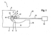
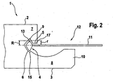
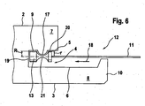
- FIGS. 1 to 7 and 10 and 11 a side edge of a panel 1 is shown in section.
- the panel 1 has an upper side 2 and a lower side 3.
- a connecting groove 4 is provided, which is surrounded by groove flanks 5, 6.
- the connecting groove 4 divides the panel 1 into an upper and a lower panel section 7, 8.
- the top side 2 facing groove flank 5 is formed approximately parallel and has a parallel to the side edge extending locking groove 9.
- the lower groove flank 6 points in the Fig. 1 to 5 and 7 a curved in the direction of the bottom 3 contour. In Fig. 6 . 10 and 11 the lower groove flank 6 is also aligned parallel to the upper side 2.
- the lower panel section 8 with the curved or parallel groove flank 6 is opposite the side edge and thus formed projecting with respect to the panel section 7 and points in the Fig. 1 to 7 an aligned in the direction of the top 2 wall portion 10.
- the height of the wall portion 10 with respect to the connecting groove 4 is selected so that a - as will be explained later - horizontal alignment of a transfer device 11 of a milling tool 12 is possible.
- a locking element is provided, which engages in the locked state in the provided in the upper groove flank 5 locking groove 9.
- a milling tool 12 consisting of a milling head 13, formed of a rigid shaft formed as a transmission device 11 and a drive 14.
- the milling head 13 has in the in the FIGS. 1 and 2 illustrated embodiment, an approximately triangular outer contour, so that thus triangular Verrieglungsnuten 9 or diamond-shaped recesses, as in Fig. 2 indicated, can be produced.
- the axes of rotation of the milling head 13 and drive 14 are aligned with each other.
- the dimensioning of the milling head 13 is selected so that a locking groove 9 triangular cross-section is generated only in the upper groove flank 5, when the rotating around the transfer device 11 milling head 13 either along the side edges or the panel 1 with the side edge along the milling tool 12 is performed.
- Fig. 3 as well as the 10 and 11 show an approximately rectangular outer contour of the milling head 13, so that a locking groove 9 can be produced with a corresponding rectangular configuration.
- the orientation of the transmission device 11 can also be aligned at an angle to the top side 2 of the panel 1. The orientation depends on the orientation of the intended locking groove 9.
- transmission device 11 as a flexible shaft and to be flexible so far to align the milling head 13 even better.
- FIGS. 4 and 5 an embodiment is shown in which between the milling head 13 and the transmission device 11, a deflection device 16 is shown in the form of an angular gear.
- This embodiment also allows the introduction of locking grooves 9 in panels 1, in which the wall portion 10 of the lower panel section 8 is designed higher than the connecting groove 4 and thus the connecting groove 4, as in Fig. 5 is shown, completely or partially hidden.
- the locking groove 9 is formed as an open area behind a projecting portion 17 of the groove flank 5 of the connecting groove 4.
- a recessed portion 20 is again provided in the insertion direction (arrow 18) seen in front of the projecting portion 17, ie in the connection groove bottom 19 remote from the region of the groove flank 5, a recessed portion 20 is again provided.
- the projecting portion 17 is curved. It is obvious that a groove flank 5 or 6 may have a plurality of mutually parallel protruding portions 17 and intervening locking grooves 9 and recessed portions 20.
- the milling head 13 has a circumferential recess 21, whose contour corresponds to the contour of the projecting portion 17. If a plurality of protruding partial regions 17 are desired, then the milling head 13 has a corresponding number of circumferential recesses 21.
- one or more locking grooves (s) 9 can be introduced into the lower and upper groove flanks 6, 5 at the same time, ie in one operation, using the method according to the invention.
- a milling head 13 is shown with an approximately semicircular cross section. As clearly shown in the figure, the milling head 13 is during insertion of the locking groove 9 with a substantial portion of its free radius r in the both sides of the groove flanks 5, 6 surrounded part of the connecting groove 4th
- Fig. 8 is shown on an enlarged scale, a milling head 13 with an approximately trapezoidal cross-section. From this figure, it is clear that the free radius r on the one hand, the actual distance between the holder-side outer edge of the milling head 13 and the outer edge of the formed as a shaft transmission device 11 is understood.
- this term also encompasses the corresponding distances between the extended projection of the outer edge of the transmission device 11 designed as a shaft and the outer edge of the milling head 13 at locations of the milling head 13 spaced axially from the holder (as a transmission shaft 11) due to the non-cylindrical shape Training the milling head 13 resulted in so far different "free radii r" along the axial extent of the milling head 13th
- the transmission device 11 also serves as a holder for the milling head 13.
- the free radius r is smaller than the actual radius R of the respective milling head thirteenth
- the holder is designed as a separate component in the form of an angle, wherein the milling head 13 is rotatably supported by a screw 23 on the holder 22.
- a ring gear 24 is integrally formed on the milling head 13, which meshes with a gear 25 driven by a drive, not shown. Due to the particular configuration of the holder 22, in this embodiment, the free radius r is greater than the actual, relative to the axis of rotation of the milling head 13 radius R, so that locking grooves 9 of great depth can be introduced.
- the milling head 13 is during insertion of the locking groove 9 with a substantial portion of its free radius r in the both sides of the groove flanks 5, 6 surrounded part of the connecting groove 4, wherein the free radius r at the same time completely between the long groove flank 6 and the extended in P projection short groove edge 5 is located.
- Fig. 11 a position of the milling head 13 is shown, in which the milling head 13 is during insertion of the locking groove 9 with its free radius r between the long groove flank 6 and extended in projection P groove flank 5.
- the milling head 13 is only in a small proportion in the part of the connecting groove 4 which surrounds the groove flank 5, 6 on both sides.
Priority Applications (1)
| Application Number | Priority Date | Filing Date | Title |
|---|---|---|---|
| PL06754125T PL1901895T3 (pl) | 2005-06-06 | 2006-06-03 | Sposób wykonywania rowka blokującego w ściance wpustu |
Applications Claiming Priority (3)
| Application Number | Priority Date | Filing Date | Title |
|---|---|---|---|
| DE102005026157 | 2005-06-06 | ||
| DE102005026554A DE102005026554B4 (de) | 2005-06-06 | 2005-06-08 | Verfahren zum Einbringen einer Verriegelungsnut in eine Nutflanke |
| PCT/EP2006/005345 WO2006131289A1 (de) | 2005-06-06 | 2006-06-03 | Verfahren zum einbringen einer verriegelungsnut in eine nutflanke |
Publications (2)
| Publication Number | Publication Date |
|---|---|
| EP1901895A1 EP1901895A1 (de) | 2008-03-26 |
| EP1901895B1 true EP1901895B1 (de) | 2009-08-12 |
Family
ID=37101376
Family Applications (1)
| Application Number | Title | Priority Date | Filing Date |
|---|---|---|---|
| EP06754125A Active EP1901895B1 (de) | 2005-06-06 | 2006-06-03 | Verfahren zum einbringen einer verriegelungsnut in eine nutflanke |
Country Status (8)
| Country | Link |
|---|---|
| US (1) | US8464768B2 (ru) |
| EP (1) | EP1901895B1 (ru) |
| AT (1) | ATE439223T1 (ru) |
| DE (2) | DE102005026554B4 (ru) |
| ES (1) | ES2331810T3 (ru) |
| PL (1) | PL1901895T3 (ru) |
| RU (1) | RU2395389C2 (ru) |
| WO (1) | WO2006131289A1 (ru) |
Families Citing this family (4)
| Publication number | Priority date | Publication date | Assignee | Title |
|---|---|---|---|---|
| SE520084C2 (sv) | 2001-01-31 | 2003-05-20 | Pergo Europ Ab | Förfarande för framställning av sammanfogningsprofiler |
| DE102007062430B3 (de) | 2007-12-20 | 2009-07-02 | Flooring Technologies Ltd. | Verfahren zum spanabhebenden Bearbeiten einer Seitenkante eines Paneels und Vorrichtung zum Durchführen des Verfahrens |
| CN106197214A (zh) * | 2016-07-15 | 2016-12-07 | 武汉船用机械有限责任公司 | 一种桩腿齿条齿厚测量工装和测量方法 |
| US10337190B2 (en) * | 2017-08-08 | 2019-07-02 | Ranat Tarananopas | Board with tongue and tenon and method for manufacture of said board with tongue and tenon |
Family Cites Families (32)
| Publication number | Priority date | Publication date | Assignee | Title |
|---|---|---|---|---|
| DE418366C (de) * | 1924-12-23 | 1925-09-05 | Delmag Deutsche Elmasch & Moto | Fraeskopf mit Antrieb durch biegsame Welle und mit je einem Handgriff in Richtung der Werkzeugachse und senkrecht dazu |
| US2835172A (en) * | 1955-01-13 | 1958-05-20 | Kearney & Trecker Corp | Rotary head milling attachment |
| US2915095A (en) * | 1958-03-25 | 1959-12-01 | Edward A Pelto | Power operated end thrust type rotary shaper planer |
| US2944466A (en) * | 1958-12-23 | 1960-07-12 | Mckay Machine Co | Profile milling machine |
| SU363795A1 (ru) | 1971-03-09 | 1972-12-25 | Центральный научно исследовательский институт механической обработки древесины | Деревянный пол |
| DE3038489C2 (de) * | 1980-10-11 | 1984-01-26 | Festo-Maschinenfabrik Gottlieb Stoll, 7300 Esslingen | Handwerkzeugmaschine mit einem rotierend angetriebenen Werkzeug |
| US5010517A (en) * | 1987-11-18 | 1991-04-23 | Hitachi, Ltd. | Semiconductor optical apparatus |
| US5025548A (en) * | 1990-06-15 | 1991-06-25 | Justesen Scott F | Right-angle drive for vertical milling machine |
| RU2171877C2 (ru) | 1993-05-10 | 2001-08-10 | Велинге Алюминиум АБ | Система для соединения строительных панелей |
| SE501014C2 (sv) | 1993-05-10 | 1994-10-17 | Tony Pervan | Fog för tunna flytande hårda golv |
| US5395188A (en) * | 1993-12-23 | 1995-03-07 | Roy E. Bowling | Guide for angled and curved drilling |
| US5697739A (en) * | 1995-06-06 | 1997-12-16 | Kennametal Inc. | Angle spindle attachment |
| US5735652A (en) * | 1995-07-21 | 1998-04-07 | Victory In Jesus Ministries | Broaching cutter |
| BE1010487A6 (nl) * | 1996-06-11 | 1998-10-06 | Unilin Beheer Bv | Vloerbekleding bestaande uit harde vloerpanelen en werkwijze voor het vervaardigen van dergelijke vloerpanelen. |
| SE515789C2 (sv) * | 1999-02-10 | 2001-10-08 | Perstorp Flooring Ab | Golvbeläggningsmaterial innefattande golvelement vilka är avsedda att sammanfogas vertikalt |
| SE514645C2 (sv) * | 1998-10-06 | 2001-03-26 | Perstorp Flooring Ab | Golvbeläggningsmaterial innefattande skivformiga golvelement avsedda att sammanfogas av separata sammanfogningsprofiler |
| US6196286B1 (en) * | 1999-12-28 | 2001-03-06 | Thermwood Corporation | Method and tool for manufacturing a shaped edge, veneer surfaced, furniture top |
| SE517183C2 (sv) * | 2000-01-24 | 2002-04-23 | Valinge Aluminium Ab | Låssystem för mekanisk hopfogning av golvskivor, golvskiva försedd med låssystemet och metod för framställning av sådana golvskivor |
| US6463824B1 (en) * | 2000-02-29 | 2002-10-15 | S-B Power Tool Company | Right angle attachment for power hand tool |
| DE10031639C2 (de) * | 2000-06-29 | 2002-08-14 | Hw Ind Gmbh & Co Kg | Fussbodenplatte |
| DE10048679A1 (de) * | 2000-09-30 | 2001-12-20 | Witex Ag | Verfahren und Vorrichtung zur Herstellung der Nut von verriegelten Nut-Feder-Verbindungen |
| US6851241B2 (en) * | 2001-01-12 | 2005-02-08 | Valinge Aluminium Ab | Floorboards and methods for production and installation thereof |
| IL156530A0 (en) * | 2001-01-12 | 2004-01-04 | Valinge Aluminium Ab | Floorboards and methods for production and installation thereof |
| SE520084C2 (sv) * | 2001-01-31 | 2003-05-20 | Pergo Europ Ab | Förfarande för framställning av sammanfogningsprofiler |
| US6568442B1 (en) * | 2001-11-28 | 2003-05-27 | Joseph Anthony Meugniot | Router bit for floorboard |
| CA2364641A1 (en) * | 2001-12-06 | 2003-06-06 | Daniel G. Kowalski | Method and apparatus for installing tongue and groove flooring |
| US6592305B1 (en) * | 2002-02-28 | 2003-07-15 | Marc H Boisvert | Right angle drive arrangement for a vertical milling machine |
| US8850769B2 (en) * | 2002-04-15 | 2014-10-07 | Valinge Innovation Ab | Floorboards for floating floors |
| US7306411B2 (en) * | 2002-09-03 | 2007-12-11 | Mitsubishi Materials Corporation | Drill with groove width variation along the drill and double margin with a thinning section at the tip |
| US20040156689A1 (en) * | 2003-02-07 | 2004-08-12 | Shen Shui Liang | Drill bit |
| US7845140B2 (en) * | 2003-03-06 | 2010-12-07 | Valinge Innovation Ab | Flooring and method for installation and manufacturing thereof |
| RU33896U1 (ru) | 2003-07-15 | 2003-11-20 | Общество с ограниченной ответственностью "Сделай сам консалтинг" | Сборно-разборное покрытие, преимущественно для пола |
-
2005
- 2005-06-08 DE DE102005026554A patent/DE102005026554B4/de not_active Expired - Fee Related
-
2006
- 2006-06-03 PL PL06754125T patent/PL1901895T3/pl unknown
- 2006-06-03 RU RU2008100030/03A patent/RU2395389C2/ru not_active IP Right Cessation
- 2006-06-03 US US11/921,839 patent/US8464768B2/en not_active Expired - Fee Related
- 2006-06-03 ES ES06754125T patent/ES2331810T3/es active Active
- 2006-06-03 WO PCT/EP2006/005345 patent/WO2006131289A1/de active Application Filing
- 2006-06-03 DE DE502006004525T patent/DE502006004525D1/de active Active
- 2006-06-03 AT AT06754125T patent/ATE439223T1/de active
- 2006-06-03 EP EP06754125A patent/EP1901895B1/de active Active
Also Published As
| Publication number | Publication date |
|---|---|
| DE102005026554A1 (de) | 2006-12-28 |
| ATE439223T1 (de) | 2009-08-15 |
| RU2008100030A (ru) | 2009-07-20 |
| EP1901895A1 (de) | 2008-03-26 |
| PL1901895T3 (pl) | 2010-02-26 |
| ES2331810T3 (es) | 2010-01-15 |
| US8464768B2 (en) | 2013-06-18 |
| US20100154935A1 (en) | 2010-06-24 |
| WO2006131289A1 (de) | 2006-12-14 |
| RU2395389C2 (ru) | 2010-07-27 |
| DE502006004525D1 (de) | 2009-09-24 |
| DE102005026554B4 (de) | 2009-06-10 |
Similar Documents
| Publication | Publication Date | Title |
|---|---|---|
| EP1087853B2 (de) | Verfahren zur spanenden bearbeitung von rotationssymmetrischen werkstückflächen | |
| EP1786578B1 (de) | Verfahren und vorrichtung zur korrektur eines schrägenfehlers eines polygonalen profils, insbesondere eines flankenrichtungsfehlers einer verzahnung | |
| DE102010061321A1 (de) | Verfahren zum Fräsen einer Ausnehmung in einem Werkstück und Werkstück mit einer Ausnehmung | |
| EP1269923A2 (de) | Chirurgisches Sägeblatt | |
| EP2954967A1 (de) | Verfahren und Vorrichtung zum stirnseitigen Anfasen einer Verzahnung eines Werkstücks | |
| DE102017107999A1 (de) | Entgratvorrichtung sowie CNC-Verzahnmaschine mit einer solchen Entgratvorrichtung | |
| EP1901895B1 (de) | Verfahren zum einbringen einer verriegelungsnut in eine nutflanke | |
| DE3737322A1 (de) | Kalibriervorrichtung fuer honsteine | |
| EP2125278A1 (de) | Stosswerkzeug, insbesondere nutstosswerkzeug | |
| EP0551795A1 (de) | Werkzeug zum Schlagbohren und Meisseln und Werkzeugaufnahme für diese Werkzeuge | |
| EP2569124B1 (de) | Verfahren zum bearbeiten einer innenseite eines eine öffnung aufweisenden gehäuses | |
| EP3741483A1 (de) | Wendeschneidplatte, schneidplattenhalter und schneidvorrichtung | |
| WO2013007252A1 (de) | Fräsverfahren und fräswerkzeug | |
| DE1966005B2 (de) | Messerwelle für die Bearbeitung von Holz, Pappe, Kunststoff oder dgl | |
| AT508493B1 (de) | Verfahren und werkzeugvorrichtung zum profilfräsen | |
| EP3592491A1 (de) | WERKZEUG, MASCHINE UND VERFAHREN ZUM ERZEUGEN VON DACHFIRSTARTIGEN ANSPITZUNGEN AN ZÄHNEN EINES INNEN- UND AUßENVERZAHNTEN ZAHNRADS | |
| EP2218829A2 (de) | Fräszahn für eine Schlitzwandfräse | |
| DE2659108C2 (de) | Verzahntes Werkzeug zum spanenden Entgraten von Zahnrädern | |
| EP1644151B1 (de) | Vorrichtung zur Bearbeitung und/oder Herstellung einer Vertiefung in einem Werkstück | |
| DE4437863C2 (de) | Rotationsbohrkopf mit radial verstellbarem Werkzeugträger | |
| EP2845695B1 (de) | Winkel für Schweißtisch | |
| EP0543348A1 (de) | Mauerstein mit einer Greifeinrichtung sowie Verfahren und Vorrichtung zur Herstellung der Greifeinrichtung | |
| EP3765679B1 (de) | Aufnahmeanordnung eines baggerzahnes mit einer aufnahme zur anordnung an der schaufel eines schaufelradbaggers | |
| EP3388161B1 (de) | Manuelle bearbeitungsvorrichtung mit abkantvorrichtung | |
| DE102006058258A1 (de) | Schaftfräser mit unterschiedlichen Schneiden |
Legal Events
| Date | Code | Title | Description |
|---|---|---|---|
| PUAI | Public reference made under article 153(3) epc to a published international application that has entered the european phase |
Free format text: ORIGINAL CODE: 0009012 |
|
| 17P | Request for examination filed |
Effective date: 20071206 |
|
| AK | Designated contracting states |
Kind code of ref document: A1 Designated state(s): AT BE BG CH CY CZ DE DK EE ES FI FR GB GR HU IE IS IT LI LT LU LV MC NL PL PT RO SE SI SK TR |
|
| AX | Request for extension of the european patent |
Extension state: AL BA HR MK YU |
|
| 17Q | First examination report despatched |
Effective date: 20080422 |
|
| GRAP | Despatch of communication of intention to grant a patent |
Free format text: ORIGINAL CODE: EPIDOSNIGR1 |
|
| GRAS | Grant fee paid |
Free format text: ORIGINAL CODE: EPIDOSNIGR3 |
|
| GRAA | (expected) grant |
Free format text: ORIGINAL CODE: 0009210 |
|
| AK | Designated contracting states |
Kind code of ref document: B1 Designated state(s): AT BE BG CH CY CZ DE DK EE ES FI FR GB GR HU IE IS IT LI LT LU LV MC NL PL PT RO SE SI SK TR |
|
| AX | Request for extension of the european patent |
Extension state: AL BA HR MK YU |
|
| REG | Reference to a national code |
Ref country code: GB Ref legal event code: FG4D Free format text: NOT ENGLISH |
|
| REG | Reference to a national code |
Ref country code: CH Ref legal event code: EP |
|
| REG | Reference to a national code |
Ref country code: IE Ref legal event code: FG4D |
|
| REF | Corresponds to: |
Ref document number: 502006004525 Country of ref document: DE Date of ref document: 20090924 Kind code of ref document: P |
|
| REG | Reference to a national code |
Ref country code: GR Ref legal event code: EP Ref document number: 20090402830 Country of ref document: GR |
|
| REG | Reference to a national code |
Ref country code: ES Ref legal event code: FG2A Ref document number: 2331810 Country of ref document: ES Kind code of ref document: T3 |
|
| LTIE | Lt: invalidation of european patent or patent extension |
Effective date: 20090812 |
|
| PG25 | Lapsed in a contracting state [announced via postgrant information from national office to epo] |
Ref country code: SE Free format text: LAPSE BECAUSE OF FAILURE TO SUBMIT A TRANSLATION OF THE DESCRIPTION OR TO PAY THE FEE WITHIN THE PRESCRIBED TIME-LIMIT Effective date: 20090812 Ref country code: IS Free format text: LAPSE BECAUSE OF FAILURE TO SUBMIT A TRANSLATION OF THE DESCRIPTION OR TO PAY THE FEE WITHIN THE PRESCRIBED TIME-LIMIT Effective date: 20091212 Ref country code: FI Free format text: LAPSE BECAUSE OF FAILURE TO SUBMIT A TRANSLATION OF THE DESCRIPTION OR TO PAY THE FEE WITHIN THE PRESCRIBED TIME-LIMIT Effective date: 20090812 Ref country code: LT Free format text: LAPSE BECAUSE OF FAILURE TO SUBMIT A TRANSLATION OF THE DESCRIPTION OR TO PAY THE FEE WITHIN THE PRESCRIBED TIME-LIMIT Effective date: 20090812 |
|
| PG25 | Lapsed in a contracting state [announced via postgrant information from national office to epo] |
Ref country code: LV Free format text: LAPSE BECAUSE OF FAILURE TO SUBMIT A TRANSLATION OF THE DESCRIPTION OR TO PAY THE FEE WITHIN THE PRESCRIBED TIME-LIMIT Effective date: 20090812 Ref country code: SI Free format text: LAPSE BECAUSE OF FAILURE TO SUBMIT A TRANSLATION OF THE DESCRIPTION OR TO PAY THE FEE WITHIN THE PRESCRIBED TIME-LIMIT Effective date: 20090812 |
|
| REG | Reference to a national code |
Ref country code: PL Ref legal event code: T3 |
|
| REG | Reference to a national code |
Ref country code: IE Ref legal event code: FD4D |
|
| PG25 | Lapsed in a contracting state [announced via postgrant information from national office to epo] |
Ref country code: PT Free format text: LAPSE BECAUSE OF FAILURE TO SUBMIT A TRANSLATION OF THE DESCRIPTION OR TO PAY THE FEE WITHIN THE PRESCRIBED TIME-LIMIT Effective date: 20091212 Ref country code: BG Free format text: LAPSE BECAUSE OF FAILURE TO SUBMIT A TRANSLATION OF THE DESCRIPTION OR TO PAY THE FEE WITHIN THE PRESCRIBED TIME-LIMIT Effective date: 20091112 |
|
| PG25 | Lapsed in a contracting state [announced via postgrant information from national office to epo] |
Ref country code: RO Free format text: LAPSE BECAUSE OF FAILURE TO SUBMIT A TRANSLATION OF THE DESCRIPTION OR TO PAY THE FEE WITHIN THE PRESCRIBED TIME-LIMIT Effective date: 20090812 Ref country code: DK Free format text: LAPSE BECAUSE OF FAILURE TO SUBMIT A TRANSLATION OF THE DESCRIPTION OR TO PAY THE FEE WITHIN THE PRESCRIBED TIME-LIMIT Effective date: 20090812 Ref country code: EE Free format text: LAPSE BECAUSE OF FAILURE TO SUBMIT A TRANSLATION OF THE DESCRIPTION OR TO PAY THE FEE WITHIN THE PRESCRIBED TIME-LIMIT Effective date: 20090812 Ref country code: IE Free format text: LAPSE BECAUSE OF FAILURE TO SUBMIT A TRANSLATION OF THE DESCRIPTION OR TO PAY THE FEE WITHIN THE PRESCRIBED TIME-LIMIT Effective date: 20090812 Ref country code: CZ Free format text: LAPSE BECAUSE OF FAILURE TO SUBMIT A TRANSLATION OF THE DESCRIPTION OR TO PAY THE FEE WITHIN THE PRESCRIBED TIME-LIMIT Effective date: 20090812 |
|
| PG25 | Lapsed in a contracting state [announced via postgrant information from national office to epo] |
Ref country code: SK Free format text: LAPSE BECAUSE OF FAILURE TO SUBMIT A TRANSLATION OF THE DESCRIPTION OR TO PAY THE FEE WITHIN THE PRESCRIBED TIME-LIMIT Effective date: 20090812 |
|
| PLBE | No opposition filed within time limit |
Free format text: ORIGINAL CODE: 0009261 |
|
| STAA | Information on the status of an ep patent application or granted ep patent |
Free format text: STATUS: NO OPPOSITION FILED WITHIN TIME LIMIT |
|
| 26N | No opposition filed |
Effective date: 20100517 |
|
| PG25 | Lapsed in a contracting state [announced via postgrant information from national office to epo] |
Ref country code: MC Free format text: LAPSE BECAUSE OF NON-PAYMENT OF DUE FEES Effective date: 20100630 |
|
| PG25 | Lapsed in a contracting state [announced via postgrant information from national office to epo] |
Ref country code: IT Free format text: LAPSE BECAUSE OF FAILURE TO SUBMIT A TRANSLATION OF THE DESCRIPTION OR TO PAY THE FEE WITHIN THE PRESCRIBED TIME-LIMIT Effective date: 20090812 |
|
| PGFP | Annual fee paid to national office [announced via postgrant information from national office to epo] |
Ref country code: GR Payment date: 20110627 Year of fee payment: 6 |
|
| PG25 | Lapsed in a contracting state [announced via postgrant information from national office to epo] |
Ref country code: CY Free format text: LAPSE BECAUSE OF FAILURE TO SUBMIT A TRANSLATION OF THE DESCRIPTION OR TO PAY THE FEE WITHIN THE PRESCRIBED TIME-LIMIT Effective date: 20090812 |
|
| PG25 | Lapsed in a contracting state [announced via postgrant information from national office to epo] |
Ref country code: LU Free format text: LAPSE BECAUSE OF NON-PAYMENT OF DUE FEES Effective date: 20100603 Ref country code: HU Free format text: LAPSE BECAUSE OF FAILURE TO SUBMIT A TRANSLATION OF THE DESCRIPTION OR TO PAY THE FEE WITHIN THE PRESCRIBED TIME-LIMIT Effective date: 20100213 |
|
| PGFP | Annual fee paid to national office [announced via postgrant information from national office to epo] |
Ref country code: GB Payment date: 20121218 Year of fee payment: 7 Ref country code: TR Payment date: 20121130 Year of fee payment: 7 Ref country code: PL Payment date: 20121129 Year of fee payment: 7 Ref country code: ES Payment date: 20121217 Year of fee payment: 7 |
|
| REG | Reference to a national code |
Ref country code: GR Ref legal event code: ML Ref document number: 20090402830 Country of ref document: GR Effective date: 20130104 |
|
| PGFP | Annual fee paid to national office [announced via postgrant information from national office to epo] |
Ref country code: NL Payment date: 20121217 Year of fee payment: 7 |
|
| PGFP | Annual fee paid to national office [announced via postgrant information from national office to epo] |
Ref country code: FR Payment date: 20130123 Year of fee payment: 7 |
|
| PG25 | Lapsed in a contracting state [announced via postgrant information from national office to epo] |
Ref country code: GR Free format text: LAPSE BECAUSE OF NON-PAYMENT OF DUE FEES Effective date: 20130104 |
|
| REG | Reference to a national code |
Ref country code: NL Ref legal event code: V1 Effective date: 20140101 |
|
| GBPC | Gb: european patent ceased through non-payment of renewal fee |
Effective date: 20130603 |
|
| REG | Reference to a national code |
Ref country code: FR Ref legal event code: ST Effective date: 20140228 |
|
| PG25 | Lapsed in a contracting state [announced via postgrant information from national office to epo] |
Ref country code: NL Free format text: LAPSE BECAUSE OF NON-PAYMENT OF DUE FEES Effective date: 20140101 Ref country code: GB Free format text: LAPSE BECAUSE OF NON-PAYMENT OF DUE FEES Effective date: 20130603 |
|
| PG25 | Lapsed in a contracting state [announced via postgrant information from national office to epo] |
Ref country code: FR Free format text: LAPSE BECAUSE OF NON-PAYMENT OF DUE FEES Effective date: 20130701 |
|
| REG | Reference to a national code |
Ref country code: ES Ref legal event code: FD2A Effective date: 20140708 |
|
| REG | Reference to a national code |
Ref country code: DE Ref legal event code: R082 Ref document number: 502006004525 Country of ref document: DE Representative=s name: DR. STARK & PARTNER PATENTANWAELTE, DE Effective date: 20140618 Ref country code: DE Ref legal event code: R081 Ref document number: 502006004525 Country of ref document: DE Owner name: DAMMERS, DIRK, DE Free format text: FORMER OWNER: DAMMERS, DIRK, 47506 NEUKIRCHEN-VLUYN, DE Effective date: 20140618 Ref country code: DE Ref legal event code: R082 Ref document number: 502006004525 Country of ref document: DE Representative=s name: DR. STARK & PARTNER PATENTANWAELTE MBB, DE Effective date: 20140618 |
|
| REG | Reference to a national code |
Ref country code: PL Ref legal event code: LAPE |
|
| PG25 | Lapsed in a contracting state [announced via postgrant information from national office to epo] |
Ref country code: ES Free format text: LAPSE BECAUSE OF NON-PAYMENT OF DUE FEES Effective date: 20130604 Ref country code: PL Free format text: LAPSE BECAUSE OF NON-PAYMENT OF DUE FEES Effective date: 20130603 |
|
| PGFP | Annual fee paid to national office [announced via postgrant information from national office to epo] |
Ref country code: CH Payment date: 20150623 Year of fee payment: 10 |
|
| PGFP | Annual fee paid to national office [announced via postgrant information from national office to epo] |
Ref country code: BE Payment date: 20150617 Year of fee payment: 10 Ref country code: AT Payment date: 20150619 Year of fee payment: 10 |
|
| PG25 | Lapsed in a contracting state [announced via postgrant information from national office to epo] |
Ref country code: TR Free format text: LAPSE BECAUSE OF NON-PAYMENT OF DUE FEES Effective date: 20130603 |
|
| PGFP | Annual fee paid to national office [announced via postgrant information from national office to epo] |
Ref country code: DE Payment date: 20150710 Year of fee payment: 10 |
|
| PG25 | Lapsed in a contracting state [announced via postgrant information from national office to epo] |
Ref country code: BE Free format text: LAPSE BECAUSE OF NON-PAYMENT OF DUE FEES Effective date: 20160630 |
|
| REG | Reference to a national code |
Ref country code: DE Ref legal event code: R119 Ref document number: 502006004525 Country of ref document: DE |
|
| REG | Reference to a national code |
Ref country code: CH Ref legal event code: PL |
|
| REG | Reference to a national code |
Ref country code: AT Ref legal event code: MM01 Ref document number: 439223 Country of ref document: AT Kind code of ref document: T Effective date: 20160603 |
|
| PG25 | Lapsed in a contracting state [announced via postgrant information from national office to epo] |
Ref country code: LI Free format text: LAPSE BECAUSE OF NON-PAYMENT OF DUE FEES Effective date: 20160630 Ref country code: CH Free format text: LAPSE BECAUSE OF NON-PAYMENT OF DUE FEES Effective date: 20160630 Ref country code: DE Free format text: LAPSE BECAUSE OF NON-PAYMENT OF DUE FEES Effective date: 20170103 |
|
| PG25 | Lapsed in a contracting state [announced via postgrant information from national office to epo] |
Ref country code: AT Free format text: LAPSE BECAUSE OF NON-PAYMENT OF DUE FEES Effective date: 20160603 |