EP1901129A2 - Automatisches Dokumentenzufuhrgerät und Bilderzeugungsvorrichtung damit - Google Patents
Automatisches Dokumentenzufuhrgerät und Bilderzeugungsvorrichtung damit Download PDFInfo
- Publication number
- EP1901129A2 EP1901129A2 EP07111184A EP07111184A EP1901129A2 EP 1901129 A2 EP1901129 A2 EP 1901129A2 EP 07111184 A EP07111184 A EP 07111184A EP 07111184 A EP07111184 A EP 07111184A EP 1901129 A2 EP1901129 A2 EP 1901129A2
- Authority
- EP
- European Patent Office
- Prior art keywords
- document
- passage
- guide
- scanned
- reversing
- Prior art date
- Legal status (The legal status is an assumption and is not a legal conclusion. Google has not performed a legal analysis and makes no representation as to the accuracy of the status listed.)
- Granted
Links
Images




Classifications
-
- G—PHYSICS
- G03—PHOTOGRAPHY; CINEMATOGRAPHY; ANALOGOUS TECHNIQUES USING WAVES OTHER THAN OPTICAL WAVES; ELECTROGRAPHY; HOLOGRAPHY
- G03G—ELECTROGRAPHY; ELECTROPHOTOGRAPHY; MAGNETOGRAPHY
- G03G15/00—Apparatus for electrographic processes using a charge pattern
- G03G15/22—Apparatus for electrographic processes using a charge pattern involving the combination of more than one step according to groups G03G13/02 - G03G13/20
- G03G15/23—Apparatus for electrographic processes using a charge pattern involving the combination of more than one step according to groups G03G13/02 - G03G13/20 specially adapted for copying both sides of an original or for copying on both sides of a recording or image-receiving material
-
- H—ELECTRICITY
- H04—ELECTRIC COMMUNICATION TECHNIQUE
- H04N—PICTORIAL COMMUNICATION, e.g. TELEVISION
- H04N1/00—Scanning, transmission or reproduction of documents or the like, e.g. facsimile transmission; Details thereof
-
- G—PHYSICS
- G03—PHOTOGRAPHY; CINEMATOGRAPHY; ANALOGOUS TECHNIQUES USING WAVES OTHER THAN OPTICAL WAVES; ELECTROGRAPHY; HOLOGRAPHY
- G03G—ELECTROGRAPHY; ELECTROPHOTOGRAPHY; MAGNETOGRAPHY
- G03G15/00—Apparatus for electrographic processes using a charge pattern
-
- G—PHYSICS
- G03—PHOTOGRAPHY; CINEMATOGRAPHY; ANALOGOUS TECHNIQUES USING WAVES OTHER THAN OPTICAL WAVES; ELECTROGRAPHY; HOLOGRAPHY
- G03G—ELECTROGRAPHY; ELECTROPHOTOGRAPHY; MAGNETOGRAPHY
- G03G15/00—Apparatus for electrographic processes using a charge pattern
- G03G15/60—Apparatus which relate to the handling of originals
- G03G15/602—Apparatus which relate to the handling of originals for transporting
-
- H—ELECTRICITY
- H04—ELECTRIC COMMUNICATION TECHNIQUE
- H04N—PICTORIAL COMMUNICATION, e.g. TELEVISION
- H04N1/00—Scanning, transmission or reproduction of documents or the like, e.g. facsimile transmission; Details thereof
- H04N1/00567—Handling of original or reproduction media, e.g. cutting, separating, stacking
- H04N1/0057—Conveying sheets before or after scanning
- H04N1/00572—Conveying sheets before or after scanning with refeeding for double-sided scanning, e.g. using one scanning head for both sides of a sheet
- H04N1/00575—Inverting the sheet prior to refeeding
- H04N1/00578—Inverting the sheet prior to refeeding using at least part of a loop, e.g. using a return loop
-
- H—ELECTRICITY
- H04—ELECTRIC COMMUNICATION TECHNIQUE
- H04N—PICTORIAL COMMUNICATION, e.g. TELEVISION
- H04N1/00—Scanning, transmission or reproduction of documents or the like, e.g. facsimile transmission; Details thereof
- H04N1/00567—Handling of original or reproduction media, e.g. cutting, separating, stacking
- H04N1/0057—Conveying sheets before or after scanning
- H04N1/00572—Conveying sheets before or after scanning with refeeding for double-sided scanning, e.g. using one scanning head for both sides of a sheet
- H04N1/00575—Inverting the sheet prior to refeeding
- H04N1/0058—Inverting the sheet prior to refeeding using at least one dead-end path, e.g. using a sheet ejection path
-
- H—ELECTRICITY
- H04—ELECTRIC COMMUNICATION TECHNIQUE
- H04N—PICTORIAL COMMUNICATION, e.g. TELEVISION
- H04N1/00—Scanning, transmission or reproduction of documents or the like, e.g. facsimile transmission; Details thereof
- H04N1/00567—Handling of original or reproduction media, e.g. cutting, separating, stacking
- H04N1/0057—Conveying sheets before or after scanning
- H04N1/00599—Using specific components
- H04N1/00602—Feed rollers
-
- H—ELECTRICITY
- H04—ELECTRIC COMMUNICATION TECHNIQUE
- H04N—PICTORIAL COMMUNICATION, e.g. TELEVISION
- H04N1/00—Scanning, transmission or reproduction of documents or the like, e.g. facsimile transmission; Details thereof
- H04N1/00567—Handling of original or reproduction media, e.g. cutting, separating, stacking
- H04N1/0057—Conveying sheets before or after scanning
- H04N1/00599—Using specific components
- H04N1/00615—Guiding elements, e.g. plates
-
- G—PHYSICS
- G03—PHOTOGRAPHY; CINEMATOGRAPHY; ANALOGOUS TECHNIQUES USING WAVES OTHER THAN OPTICAL WAVES; ELECTROGRAPHY; HOLOGRAPHY
- G03G—ELECTROGRAPHY; ELECTROPHOTOGRAPHY; MAGNETOGRAPHY
- G03G2215/00—Apparatus for electrophotographic processes
- G03G2215/00172—Apparatus for electrophotographic processes relative to the original handling
- G03G2215/00177—Apparatus for electrophotographic processes relative to the original handling for scanning
- G03G2215/00181—Apparatus for electrophotographic processes relative to the original handling for scanning concerning the original's state of motion
- G03G2215/00189—Apparatus for electrophotographic processes relative to the original handling for scanning concerning the original's state of motion original moving
-
- H—ELECTRICITY
- H04—ELECTRIC COMMUNICATION TECHNIQUE
- H04N—PICTORIAL COMMUNICATION, e.g. TELEVISION
- H04N2201/00—Indexing scheme relating to scanning, transmission or reproduction of documents or the like, and to details thereof
- H04N2201/0077—Types of the still picture apparatus
- H04N2201/0091—Digital copier; digital 'photocopier'
Definitions
- the present invention relates to an image forming apparatus, such as a multifunction machine or a copier. More particularly, the present general inventive concept relates to an automatic document feeder of an image forming apparatus having a duplex printing function.
- an image forming apparatus such as a multifunction machine, a copier, or the like, is provided with an automatic document feeder, which continuously and automatically feeds a document to be scanned onto a document scanning part of a scanner unit.
- the automatic document feeder usually has a single scan path, and a duplex scan path to reverse the document, one surface of which is scanned, and to admit(feed) the reversed document to the document scanning part.
- FIG. 1 illustrates a conventional automatic document feeder.
- reference numerals 1, 2, 10 and 20 represent a document feeder frame, a document scanning part, a single scan path, and a duplex scan path, respectively.
- the single scan path 10 is provided with a document admission passage 12 to admit or feed a document D of a document supplying tray 11 to the document scanning part 2 and a document discharge passage 13 to discharge the scanned document.
- the duplex scan path 20 is connected from the document discharge passage 13 to the single scan path 10 at front of the document scanning part 2.
- reference numerals 14-17 and 21 represents document conveying rollers.
- the document D In a single printing mode, the document D is scanned passing through in turn, paths a, b, c, d, e, and f whereas in a duplex printing mode, the document D, both surfaces of which are scanned passing through the single scan path as described above, is scanned and discharged in a state that it is reversed passing through paths g, h, c, d, e, and f.
- the document having the both surfaces scanned is discharged through the duplex scan path 20 in the duplex printing mode, it requires that the document is discharged in a state that it is collated in the same page as that in an admission thereof in the document admission passage 12. For this, before being discharged, the document having the both surfaces scanned is to pass through the duplex scan path (paths g, h, c, d, e, and f) again.
- the duplex printing mode As described above, in the duplex printing mode, after the preceding document is completely discharged passing through a, b, c, d, e, f, g, h, c, d, e, f, g, h, c, d, e, and f in turn, the following document is to be admitted into the document admission passage 12. Accordingly, a printing efficiency in the duplex printing mode is very low. In this case, the printing efficiency is no more than approximately 40% of that in the single printing mode.
- a method is employed to shorten the duplex scan path and move a conveying roller away from a corresponding backup roller at a place where the documents overlaps each other. In this case, however, to collate and discharge the document having the both surfaces scanned, the document should pass through the duplex scan path again. Accordingly, there is a limit to increase the printing efficiency.
- the present invention provides an automatic document feeder to scan a document and collate and discharge the scanned document having both surfaces scanned, thereby reducing a document admission interval in a duplex scanning or printing mode and thus improving a duplex scanning or printing efficiency in the duplex scanning, or printing mode.
- the present invention also provides an image forming apparatus, which has the automatic document feeder as described above, thereby improving a scanning or printing speed.
- an automatic document feeder of an image forming apparatus in which a document discharge passage, a first document reversing passage to reverse a document to carry out a duplex scanning or printing mode, and a second document reversing passage to reverse the document again thus to collate it are formed separately from one another, so that, in use, while the document, both surfaces of which are scanned, is collated and discharged, a next document can be scanned.
- the automatic document feeder may include a single scan path having a document admission passage to admit a document to a document scanning part and a document discharge passage to discharge the scanned document, a duplex scan path having a first document reversing and waiting passage diverged separately from the document discharge passage on the single scan path at the rear of the document scanning part to reverse the document, one surface of which is scanned, and admit again the reversed document to the document scanning part, and a document re-reversing path having a second document reversing and waiting passage diverged separately from the document discharge passage on the single scan path at the rear of the document scanning part to reverse the document, both surfaces of which are scanned, again and send the re-reversed document to the document discharge passage.
- the automatic document feeder may further include a document guide unit formed at a diverging point of the first document reversing and waiting passage and the second document reversing and waiting passage to the single scan path to guide the scanned document to a corresponding passage.
- the document guide unit may guide the scanned document to the document discharge passage in case of a single scanning or printing mode, whereas guide the document having the one surface scanned to the first document reversing and waiting passage and guide the document having both surfaces scanned to the second document reversing and waiting passage in case of a duplex scanning or printing mode.
- the document guide unit may include upper and lower fixed guides disposed above and below the diverging point, respectively, a movable guide disposed to be rotatable about an axis between the upper and lower fixed guides, and having an upper guide part, a lower guide part and a passage formed between the upper guide part and the lower guide part, and a rotation driving unit to rotate the movable guide in a position corresponding to a scanning mode.
- the rotation driving unit may include a motor connected to the axis of the movable guide, and a control unit to determine the scanning mode and thus to control a drive of the motor.
- the rotation driving unit may include an elastic member to elastically support the movable guide in one of an upward direction and a downward direction, a rotation pressing unit to rotate the movable guide by stages in an opposite direction to an elastic force direction of the elastic member, a sensor member to detect an initial position of the movable guide, and a control unit to determine a scanning mode and to receive a signal from the sensor member thus to drive the rotation pressing unit.
- the rotation pressing unit may include a cam gear rotatably disposed on the axis of the movable guide and having a cam on which at least three pushing parts are formed to have distances different from a center thereof, respectively, a clutch gear coaxially connected to and rotated along with the cam gear, and having three stopping projections formed on a circumferential surface thereof, a driving gear to rotate the cam gear, and a solenoid to come in contact with the stopping projections of the clutch gear thus to restrict a rotation of the clutch gear.
- the upper and the lower fixed guides and the upper and the lower guide parts of the movable guide may have a plurality of ribs and corresponding ribs, respectively, which are interdigitated with one another so as not to interfere with one another in a rotation of the movable guide.
- the movable guide may rotate in a first position to open a passage between the upper fixed guide and the upper guide part of the movable guide, a second position to communicate a passage between the upper and the lower guide parts with the document discharge passage, and a third position to open a passage between the lower fixed guide and the lower guide part of the movable guide.
- the passage between the upper fixed guide and the upper guide part at the first position of the movable guide is communicated with the first document reversing and waiting passage
- the passage between the lower fixed guide and the lower guide part at the third position of the movable guide is communicated with the second document reversing and waiting passage.
- an image forming apparatus including a main body having a printer unit disposed therein, a scanner unit disposed on the main body, and an automatic document feeder in which a document discharge passage, a first document reversing passage to reverse a document to carry out a duplex scanning or printing mode, and a second document reversing passage to reverse the document again thus to collate it are formed separately from one another, so that, in use, while the document, both surfaces of which are scanned, is collated and discharged, a next document can be scanned.
- image forming apparatus including a scanner unit to scan a document, and a document feeder to feed the document to the scanner unit, the document feeder including a first frame having a document admission passage of the document, a second frame to form a first document reversing and waiting passage with the first frame, a third frame to form a document discharging passage with the second frame, and a fourth frame to form a second document reversing and waiting passage with the third frame.
- an image forming apparatus including a scanner unit to scan a document, and a document feeder to feed the document to the scanner, and the document feeder including a document admission passage to feed the document to the scanner unit, a first document reversing and waiting passage to feed the scanned document back to the document admission passage, so that the scanning unit scans another surface of the scanned document, a second document reversing and waiting passage to reverse the scanned document, and a document discharging passage to discharge the document received the document admission passage and the second document reversing and waiting passage.
- an image forming apparatus including a scanner unit to scan a document, and a document feeder to feed the document to the scanner unit, to discharge the scanned document, and to reverse the scanned document in a duplex mode, the document feeder including a first passage to reverse the scanned document, and a second passage to reverse the document reversed in the first passage and scanned by the scanner unit before being discharged.
- FIG. 2 is a schematic view exemplifying an automatic document feeder usable in an image forming and/or scanning apparatus according to an embodiment of the present general inventive concept
- FIG. 3 is a detail view exemplifying a portion of the automatic document feeder of FIG. 2.
- reference numerals 100 and 200 represent a document feeder frame and a document scanning part, respectively.
- the automatic document feeder includes a single scan path 110, a duplex scan path 120, a document re-reversing path 130, and a document guide unit 140.
- the single scan path 110 is provided with a document admission passage 112 to admit (or feed) a document placed on a document supplying tray 111 to the document scanning part 200 and a document discharge passage 114 to discharge the document scanned via the document scanning part 200 to a document discharging tray 113.
- a plurality of conveying rollers 115 through 119 are disposed in given intervals on the single scan path 110 to convey the document.
- the duplex scan path 120 is provided with a first document reversing and waiting passage 121 diverged separately from the document discharge passage 114 on the single scan path 110 at the rear of the document scanning part 200.
- the duplex scan path 120 is connected to the single scan path 110 in front of the document scanning part 200to reverse the document, one surface of which is scanned, and admit (or feed) the reversed document again to the document scanning part 200 to scan the other surface of the document.
- a conveying roller 122 On the duplex scan path 120 is disposed a conveying roller 122, which is rotatable in forward and backward directions.
- the document may be a sheet of paper on which one or more images and/or text are formed on one side (surface) and/or the other side (surface).
- the document re-reversing path 130 is provided with a second document reversing and waiting passage 131 diverged separately from the document discharge passage 114 on the single scan path 110 at the rear of the document scanning part 200, and a connecting passage 132 to connect the second document reversing and waiting passage 131 and the document discharge passage 114 with each other.
- the document re-reversing path 130 reverses the document, both surfaces of which are scanned, again and then discharges it through the document discharge passage 114, so that the discharged document is collated in the same page as that in an admission thereof in the document admission passage 112.
- On the document re-reversing path 130 is disposed a conveying roller 133, which is rotatable in forward and backward directions.
- the other document feeder frame 100 may include a first frame 100a, a second frame 100b to form the document admission passage 112 with the first frame 100a, a third frame 100c to form the first document reversing and waiting passage 121 with the second frame 100b, a fourth frame 100d to form the document discharging passage 114 with the third frame 100c, a fifth frame 100e to form the second document reversing and waiting passage 131 with the fourth frame 100d, and a sixth frame 100f to form a reverse passage between the document admission passage 112 and the first document reversing and waiting passage 121 with the second frame 100b.
- the automatic document feeder may be configured so that the document discharge passage 114, the first document reversing and waiting passage 121 to reverse the document having one surface scanned to carry out a duplex scanning or printing mode, and the second document reversing and waiting passage 131 to collate the document having both surfaces scanned and then discharge it are formed separately from one another. Accordingly, while the preceding document having both surfaces scanned is collated and discharged, the following document can be scanned.
- a passage to reverse a document to carry out a duplex scanning or printing mode and a passage to reverse the document again thus to collate it use a document discharge passage in common. Accordingly, a following next document to be scanned cannot be admitted or fed into a document admission passage until the preceding document is reversed again and thus collated to be discharged. As a result, an interval between the documents admitted into the document admission passage 112 is lengthened.
- the document guide unit 140 of the automatic document feeder is formed at a diverging point of the first document reversing and waiting passage 121 and the second document reversing and waiting passage 131 to the single scan path 110 to guide and move the document scanned via the document scanning part 200 to a passage corresponding to a state thereof.
- the document guide unit 140 guides the scanned document to the document discharge passage 114 in case of a single scanning or printing mode. However, the document guide unit 140 guides the document having the one surface scanned to the first document reversing and waiting passage 121 and guides the document having both surfaces scanned to the second document reversing and waiting passage 131 in case of a duplex scanning or printing mode.
- the document guide unit 140 includes upper and lower fixed guides 141 and 142, a movable guide 144, and a rotation driving unit 150.
- the upper and lower fixed guides 141 and 142 are disposed above and below the diverging point, respectively.
- the movable guide 144 is disposed to be rotatabe about an axis of a shaft 143 between the upper and lower fixed guides 141 and 142, and has an upper guide part 145, a lower guide part 146, and a passage 147 formed between the upper guide part 145 and the lower guide part 146.
- the rotation driving unit 150 rotates the movable guide 144 in a position corresponding to a scanning mode.
- the shaft 143 is disposed on a first divider 129 located between the first document and waiting passage 121 and the document discharging passage 114.
- a second divider 139 is disposed between the document discharging passage 114 and the second document and waiting passage 131 to correspond to the connecting passage 132.
- the upper and the lower fixed guides 141 and 142 and the upper and the lower guide parts 145 and 146 of the movable guide 144 have a plurality of ribs (not illustrated) and corresponding ribs (not illustrated), respectively, which are interdigitated with one another so as not to interfere with one another when the movable guide 144 is rotated to change a position thereof.
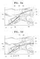
- the movable guide 144 rotates in a first position (see FIG. 5A) to open a first passage between the upper fixed guide 141 and the upper guide part 145 of the movable guide 144, a second position (see FIG. 5B) to connect a second passage, i.e., the passage 147, between the upper and the lower guide parts 145 and 146 to the document discharge passage 114, and a third position (see FIG. 5C) to open a third passage between the lower fixed guide 142 and the lower guide part 146 of the movable guide 144.
- the first passage between the upper fixed guide 141 and the upper guide part 145 at the first position of the movable guide 144 communicates with the first document reversing and waiting passage 121
- the third passage between the lower fixed guide 142 and the lower guide part 146 at the third position of the movable guide 144 communicates with the second document reversing and waiting passage 131.
- the upper guide part 145 may be a flat-shaped plate
- the lower guide part 146 may be a curved plate to form a connection, such as a curved surface, between the passage 112 and the passage 114 or 131.
- the rotation driving unit 150 includes an elastic member 151, a rotation pressing unit 160, a sensor member 153, and a control unit 155.
- the elastic member 151 elastically supports the movable guide 144 in one of an upward direction and a downward direction.
- the rotation pressing unit 160 rotates the movable guide 144 by stages in an opposite direction to an elastic force direction of the elastic member 151.
- the sensor member 153 detects an initial position of the movable guide 144.
- the control unit 155 determines the scanning mode and receives a signal from the sensor member 153 thus to drive the rotation pressing unit 160.
- the rotation pressing unit 160 is provided with a cam gear 161 rotatably disposed on the axis of the shaft 143 of the movable guide 144, a clutch gear 163 coaxially connected to and rotated along with the cam gear 161, a driving gear 165 to rotate the cam gear 161, and a solenoid 167 to selectively restrict a rotation of the clutch gear 163.
- the driving gear 165 may be connected to an external power source to rotate the cam gear 161 and/or to move the movable guide 141.
- the cam gear 161 has a cam (not illustrated) in which at least three pushing parts are formed to have distances different from a center thereof, respectively. As the cam gear 161 rotates, the respective pushing parts of the cam gear 161 push the movable guide 144 by stages and thereby the movable guide 144 is rotated about the shaft 143 to change the position thereof, so that the movable guide 144 moves to the first position, the second position, or the third position.
- the clutch gear 163 has three stopping projections 163a projected in equal intervals of 120° on a circumferential surface thereof to correspond to the respective pushing parts and to maintain a position of the movable guide 144, and the solenoid 167 has an actuating projection 167a, which comes in contact with the stopping projections 163a of the clutch gear 163.
- the cam gear 161 is configured, so that a toothed part partly formed thereon is engaged with and rotated by the driving gear 165. Accordingly, if a rotation of the cam gear 161 is restricted by the solenoid 167, the driving gear 165 comes to face a non-toothed part of the cam gear 161. As a result, the driving gear 165 is rotated, but the cam gear 161 is not rotated. When the solenoid 167 releases the corresponding stopping projection 163a, the cam gear 161 rotates by the driving gear 165 to move the movable guide 141.
- the rotation pressing unit 150 rotating the movable guide 144 is illustrated and explained as having the construction as described above, but the present general inventive concept is not limited thereto.
- the rotation pressing unit 150 it is possible for the rotation pressing unit 150 to configure in a construction that connects a motor, for example, a stepping motor, which is rotatable in forward and backward directions, to the shaft 143 of the movable guide 144 and properly controls a drive of the motor with the control unit 155 thus to change a position of the movable guide 144 according to the scanning mode.
- a motor for example, a stepping motor, which is rotatable in forward and backward directions
- the movable guide 144 In a single scanning or printing mode, the movable guide 144 is located atthe second position as illustrated in FIG. 5B by the control unit 155. That is, the movable guide 144 is positioned, so that the passage 147 of the movable guide 144 is connected to the document admission passage 112 and the document discharge passage 114 to communicate with each other. After moving via the document scanning part 200, a document is conveyed into the document discharge passage 114 through the passage 147 and discharged therethrough.
- the scan path in the single scanning or printing mode as described above is the same as that of the conventional automatic document feeder. That is, as illustrated in FIG. 2, the document passes through paths a, b, c, d, and e.
- the movable guide 144 In a duplex scanning or printing mode, the movable guide 144 is located at the first position as illustrated in FIG. 5A by the control unit 155. That is, the movable guide 144 is rotated in a position where the passage between the upper fixed guide 141 and the upper guide part 145 of the movable guide 144 is opened so that the document admission passage 112 is connected to the first document reversing and waiting passage 121. With this, a document, one surface of which is scanned, is conveyed to the first document reversing and waiting passage 121, admitted into the duplex scan path 120 in a reversed state by rotating the conveying roller 122 in a backward direction, and then conveyed passing through the document scanning part 200 in the reversed state.
- the control unit 155 moves the movable guide 144 in the first position as illustrated in FIG. 5C. That is, the movable guide 144 is rotated in a position where the passage between the lower fixed guide 142 and the lower guide part 146 of the movable guide 144 is opened so that the document admission passage 112 is connected to the second document reversing and waiting passage 131. Accordingly, the document, both surfaces of which are scanned, is conveyed to the second document reversing and waiting passage 131, conveyed via the connecting passage 132 in a re-reversed state by rotating the conveying roller 133 in a backward direction, and then discharged through the document discharge passage 114 in the re-reversed state.
- the document path in the duplex scanning or printing mode as described above is made up of an order of paths a, b, c, f, g, h, d, c, i, j, k and e, as illustrated in
- the document is discharged to have a scanned surface face down in the single scan mode, and the document is also discharged to have the same scanned surface face down in the duplex scanning mode since the document has been re-reversed.
- FIG. 6 illustrates a multifunction machine, such as an image forming apparatus, having an automatic document feeder 300 according to an embodiment of the present general inventive concept.
- the image forming apparatus includes a printer unit 410 disposed in a main body 400, and a scanner unit 420 mounted on the main body 400.
- An automatic document feeder 300 is disposed on the scanner unit 420.
- the scanner unit 420 scans an image from a document, which is continuously conveyed by the automatic document feeder 300.
- the scanned image information is transmitted to the printer unit 410, and the printer unit 410 prints or copies the scanned image on a printing paper.
- the printing paper is supplied to the printer unit 410 from a paper supplying unit 430 disposed below the main body 400.
- a printing efficiency in the duplex printing mode was approximately 90% of that in the single printing mode.
- the printing efficiency in the duplex printing mode usually is approximately 50% of that in the single printing mode
- the duplex printing speed of the image forming apparatus according to the exemplary embodiment of the present general inventive concept can be evaluated at an epoch of a shortened scanned period.
- the automatic document feeder and the image forming apparatus can improve the scanning or printing efficiency in the duplex scanning or printing mode, thereby realizing a high speed image forming apparatus, that is, a high speed multifunction machine, copier, printer or the like.
Landscapes
- Engineering & Computer Science (AREA)
- Multimedia (AREA)
- Signal Processing (AREA)
- Physics & Mathematics (AREA)
- General Physics & Mathematics (AREA)
- Separation, Sorting, Adjustment, Or Bending Of Sheets To Be Conveyed (AREA)
- Facsimiles In General (AREA)
- Conveyance By Endless Belt Conveyors (AREA)
- Exposure Or Original Feeding In Electrophotography (AREA)
Applications Claiming Priority (1)
| Application Number | Priority Date | Filing Date | Title |
|---|---|---|---|
| KR1020060088616A KR101248871B1 (ko) | 2006-09-13 | 2006-09-13 | 자동 원고 이송장치 및 이를 구비한 화상형성장치 |
Publications (3)
| Publication Number | Publication Date |
|---|---|
| EP1901129A2 true EP1901129A2 (de) | 2008-03-19 |
| EP1901129A3 EP1901129A3 (de) | 2013-08-28 |
| EP1901129B1 EP1901129B1 (de) | 2018-08-15 |
Family
ID=38874987
Family Applications (1)
| Application Number | Title | Priority Date | Filing Date |
|---|---|---|---|
| EP07111184.3A Not-in-force EP1901129B1 (de) | 2006-09-13 | 2007-06-27 | Automatisches Dokumentenzufuhrgerät und Bilderzeugungsvorrichtung damit |
Country Status (4)
| Country | Link |
|---|---|
| US (2) | US7876479B2 (de) |
| EP (1) | EP1901129B1 (de) |
| KR (1) | KR101248871B1 (de) |
| CN (1) | CN101144999B (de) |
Families Citing this family (12)
| Publication number | Priority date | Publication date | Assignee | Title |
|---|---|---|---|---|
| TWI225462B (en) * | 2003-07-28 | 2004-12-21 | Avision Inc | Duplex/simplex automatic sheet feeder |
| TWI357532B (en) * | 2008-02-29 | 2012-02-01 | Primax Electronics Ltd | Duplex scanning apparatus |
| TWI361755B (en) * | 2009-06-16 | 2012-04-11 | Kinpo Elect Inc | Paper feeding device |
| US8854706B2 (en) * | 2009-07-07 | 2014-10-07 | Kabushiki Kaisha Toshiba | Auto document feeding device |
| US20120033272A1 (en) * | 2010-08-03 | 2012-02-09 | Yueh-Shing Lee | Calibration Mechanism And Scanning Device Has The Calibration Mechanism |
| US8466941B2 (en) * | 2011-01-24 | 2013-06-18 | Kabushiki Kaisha Toshiba | Sheet conveying apparatus, erasing apparatus, and image forming apparatus |
| US8649073B2 (en) * | 2011-06-10 | 2014-02-11 | Hewlett-Packard Development Company, L.P. | Configurable scanner assembly |
| JP5966610B2 (ja) * | 2011-07-29 | 2016-08-10 | ブラザー工業株式会社 | 画像形成装置 |
| JP6057540B2 (ja) * | 2012-05-07 | 2017-01-11 | キヤノン株式会社 | 画像形成装置 |
| JP2013236158A (ja) * | 2012-05-07 | 2013-11-21 | Canon Inc | 画像読取装置、及び、それを有する画像形成装置 |
| TW201349837A (zh) * | 2012-05-18 | 2013-12-01 | Primax Electronics Ltd | 雙面影像掃描裝置及其饋紙控制方法 |
| JP6361620B2 (ja) * | 2015-09-28 | 2018-07-25 | 京セラドキュメントソリューションズ株式会社 | 読取装置、これを備えた画像形成装置 |
Citations (6)
| Publication number | Priority date | Publication date | Assignee | Title |
|---|---|---|---|---|
| US5669056A (en) | 1996-03-25 | 1997-09-16 | Xerox Corp | Duplex document handling system |
| JPH11298667A (ja) | 1998-04-14 | 1999-10-29 | Konica Corp | 原稿搬送装置及び画像読取装置 |
| US6209861B1 (en) | 1998-03-11 | 2001-04-03 | Kyocera Mita Corporation | Sheet transport device and automatic document feeder |
| US20010048830A1 (en) | 2000-06-06 | 2001-12-06 | Murata Kikai Kabushiki Kaisha | Image scanning apparatus |
| JP2005311954A (ja) | 2004-04-26 | 2005-11-04 | Sharp Corp | 原稿読取方法 |
| US20060062615A1 (en) | 2004-09-17 | 2006-03-23 | Toru Horio | Image forming method and apparatus capable of automatically conveying documents |
Family Cites Families (20)
| Publication number | Priority date | Publication date | Assignee | Title |
|---|---|---|---|---|
| US5502556A (en) * | 1992-07-14 | 1996-03-26 | Konica Corporation | Automatic document feeding apparatus for feeding two-sided documents |
| DE19609435A1 (de) * | 1995-03-10 | 1996-09-19 | Ricoh Kk | Umkehrpfad für eine automatische Zuführeinrichtung für einen Bilderzeugungsapparat |
| JP3081500B2 (ja) * | 1995-04-18 | 2000-08-28 | キヤノン株式会社 | 自動原稿送り装置、原稿自動読取装置及び画像形成装置 |
| US5784680A (en) * | 1995-10-11 | 1998-07-21 | Ricoh Company, Ltd. | Compact auto-document feeder for an image forming apparatus |
| JP3215811B2 (ja) * | 1997-11-21 | 2001-10-09 | 京セラミタ株式会社 | 原稿読取装置 |
| JP3765701B2 (ja) * | 1999-10-28 | 2006-04-12 | ニスカ株式会社 | 用紙供給装置及び用紙処理方法 |
| JP3752413B2 (ja) * | 2000-02-02 | 2006-03-08 | ニスカ株式会社 | 用紙搬送装置、及び用紙搬送装置における用紙の供給方法 |
| CN2502903Y (zh) * | 2001-12-04 | 2002-07-31 | 旭丽股份有限公司 | 自动走纸器 |
| US6778787B2 (en) * | 2002-04-05 | 2004-08-17 | Canon Kabushiki Kaisha | Image forming apparatus with control to divert sheet to usable path |
| KR100441543B1 (ko) * | 2002-05-09 | 2004-07-23 | 삼성전자주식회사 | 양면인쇄 가능한 화상형성 장치 |
| CN2543710Y (zh) * | 2002-05-24 | 2003-04-09 | 旭丽股份有限公司 | 一种双面自动进纸装置 |
| JP4006591B2 (ja) * | 2003-03-31 | 2007-11-14 | ブラザー工業株式会社 | 原稿反転搬送装置 |
| TWI225462B (en) * | 2003-07-28 | 2004-12-21 | Avision Inc | Duplex/simplex automatic sheet feeder |
| JP4151532B2 (ja) * | 2003-09-17 | 2008-09-17 | コニカミノルタビジネステクノロジーズ株式会社 | 原稿搬送装置 |
| JP4500728B2 (ja) * | 2005-04-28 | 2010-07-14 | キヤノン株式会社 | 自動原稿給送装置および画像形成装置 |
| TWI271097B (en) * | 2005-10-07 | 2007-01-11 | Asia Optical Co Inc | Automatic document feeder |
| TWI271316B (en) * | 2006-03-07 | 2007-01-21 | Avision Inc | Simplex and duplex continuous automatic document feeder |
| US7578504B2 (en) * | 2006-09-15 | 2009-08-25 | Lite-On Technology Corp. | Duplex automatic document feeder |
| US20080265501A1 (en) * | 2007-04-26 | 2008-10-30 | Foote Wayne E | Preflipping sheets for a duplex operation |
| US8544840B2 (en) * | 2007-04-30 | 2013-10-01 | Hewlett-Packard Development Company, L.P. | Automatic document feeder |
-
2006
- 2006-09-13 KR KR1020060088616A patent/KR101248871B1/ko not_active Expired - Fee Related
-
2007
- 2007-05-08 US US11/745,648 patent/US7876479B2/en active Active
- 2007-06-27 EP EP07111184.3A patent/EP1901129B1/de not_active Not-in-force
- 2007-07-05 CN CN2007101274121A patent/CN101144999B/zh not_active Expired - Fee Related
-
2010
- 2010-12-15 US US12/968,323 patent/US8498027B2/en not_active Expired - Fee Related
Patent Citations (6)
| Publication number | Priority date | Publication date | Assignee | Title |
|---|---|---|---|---|
| US5669056A (en) | 1996-03-25 | 1997-09-16 | Xerox Corp | Duplex document handling system |
| US6209861B1 (en) | 1998-03-11 | 2001-04-03 | Kyocera Mita Corporation | Sheet transport device and automatic document feeder |
| JPH11298667A (ja) | 1998-04-14 | 1999-10-29 | Konica Corp | 原稿搬送装置及び画像読取装置 |
| US20010048830A1 (en) | 2000-06-06 | 2001-12-06 | Murata Kikai Kabushiki Kaisha | Image scanning apparatus |
| JP2005311954A (ja) | 2004-04-26 | 2005-11-04 | Sharp Corp | 原稿読取方法 |
| US20060062615A1 (en) | 2004-09-17 | 2006-03-23 | Toru Horio | Image forming method and apparatus capable of automatically conveying documents |
Also Published As
| Publication number | Publication date |
|---|---|
| US20080062477A1 (en) | 2008-03-13 |
| KR101248871B1 (ko) | 2013-03-28 |
| US8498027B2 (en) | 2013-07-30 |
| CN101144999A (zh) | 2008-03-19 |
| US7876479B2 (en) | 2011-01-25 |
| CN101144999B (zh) | 2012-11-14 |
| US20110085217A1 (en) | 2011-04-14 |
| KR20080024357A (ko) | 2008-03-18 |
| EP1901129B1 (de) | 2018-08-15 |
| EP1901129A3 (de) | 2013-08-28 |
Similar Documents
| Publication | Publication Date | Title |
|---|---|---|
| EP1901129A2 (de) | Automatisches Dokumentenzufuhrgerät und Bilderzeugungsvorrichtung damit | |
| US8016283B2 (en) | Recording sheet feeder and image forming apparatus providing easy maintenance with simple structure | |
| US7896343B2 (en) | Document or sheet material feeder | |
| EP1959660A1 (de) | Bildlesevorrichtung mit Fähigkeit zur Duplexabtastung und Bilderzeugungsvorrichtung damit | |
| KR100632905B1 (ko) | 시트 반송 장치 및 화상 판독 장치 | |
| US4627709A (en) | Automatic sheet feeder and an image recording apparatus provided therewith | |
| US6321063B1 (en) | Document conveyance device having drop-prevention mechanism, and image reproducing apparatus equipped therewith | |
| US20070284804A1 (en) | Document feeding device and image reading apparatus using the same | |
| CN1321870C (zh) | 纸张处理装置及纸张处理方法 | |
| JP2524748B2 (ja) | 原稿搬送装置付き複写機 | |
| JP5064518B2 (ja) | 自動原稿搬送装置、及びこれを備えた画像形成装置 | |
| JP4198118B2 (ja) | 画像形成装置 | |
| US7699304B2 (en) | Paper feed structure for an image forming apparatus | |
| JP7151235B2 (ja) | 給紙装置及び画像形成装置 | |
| JP3816283B2 (ja) | シート搬送装置 | |
| JP3755512B2 (ja) | 画像形成装置 | |
| US20240400332A1 (en) | Media ejecting device | |
| JP4336599B2 (ja) | シート搬送装置及び画像処理装置 | |
| KR200358849Y1 (ko) | 시트 피드방식 사무자동화기기의 양면 스캐닝장치 | |
| JP3329852B2 (ja) | 原稿搬送装置 | |
| JP3640879B2 (ja) | シート材搬送機構及びこのシート材搬送機構を備えた画像形成装置 | |
| JP2024108467A (ja) | 開閉装置、シート搬送装置、画像読取装置及び画像形成装置 | |
| KR20000011525A (ko) | 분리가능한판독장치를구비한화상형성장치 | |
| JP2004098530A (ja) | 画像形成装置 | |
| JP2002128311A (ja) | ローラ切替え機構及びこのローラ切替え機構を備えた画像形成装置 |
Legal Events
| Date | Code | Title | Description |
|---|---|---|---|
| PUAI | Public reference made under article 153(3) epc to a published international application that has entered the european phase |
Free format text: ORIGINAL CODE: 0009012 |
|
| AK | Designated contracting states |
Kind code of ref document: A2 Designated state(s): AT BE BG CH CY CZ DE DK EE ES FI FR GB GR HU IE IS IT LI LT LU LV MC MT NL PL PT RO SE SI SK TR |
|
| AX | Request for extension of the european patent |
Extension state: AL BA HR MK YU |
|
| RAP1 | Party data changed (applicant data changed or rights of an application transferred) |
Owner name: SAMSUNG ELECTRONICS CO., LTD. |
|
| PUAL | Search report despatched |
Free format text: ORIGINAL CODE: 0009013 |
|
| AK | Designated contracting states |
Kind code of ref document: A3 Designated state(s): AT BE BG CH CY CZ DE DK EE ES FI FR GB GR HU IE IS IT LI LT LU LV MC MT NL PL PT RO SE SI SK TR |
|
| AX | Request for extension of the european patent |
Extension state: AL BA HR MK RS |
|
| RIC1 | Information provided on ipc code assigned before grant |
Ipc: H04N 1/00 20060101ALI20130723BHEP Ipc: G03G 15/00 20060101AFI20130723BHEP Ipc: G03G 15/23 20060101ALI20130723BHEP |
|
| 17P | Request for examination filed |
Effective date: 20140228 |
|
| RBV | Designated contracting states (corrected) |
Designated state(s): AT BE BG CH CY CZ DE DK EE ES FI FR GB GR HU IE IS IT LI LT LU LV MC MT NL PL PT RO SE SI SK TR |
|
| AKX | Designation fees paid |
Designated state(s): AT BE BG CH CY CZ DE DK EE ES FI FR GB GR HU IE IS IT LI LT LU LV MC MT NL PL PT RO SE SI SK TR |
|
| 17Q | First examination report despatched |
Effective date: 20140626 |
|
| RAP1 | Party data changed (applicant data changed or rights of an application transferred) |
Owner name: S-PRINTING SOLUTION CO., LTD. |
|
| GRAP | Despatch of communication of intention to grant a patent |
Free format text: ORIGINAL CODE: EPIDOSNIGR1 |
|
| STAA | Information on the status of an ep patent application or granted ep patent |
Free format text: STATUS: GRANT OF PATENT IS INTENDED |
|
| INTG | Intention to grant announced |
Effective date: 20180409 |
|
| RAP1 | Party data changed (applicant data changed or rights of an application transferred) |
Owner name: HP PRINTING KOREA CO., LTD. |
|
| GRAS | Grant fee paid |
Free format text: ORIGINAL CODE: EPIDOSNIGR3 |
|
| GRAA | (expected) grant |
Free format text: ORIGINAL CODE: 0009210 |
|
| STAA | Information on the status of an ep patent application or granted ep patent |
Free format text: STATUS: THE PATENT HAS BEEN GRANTED |
|
| AK | Designated contracting states |
Kind code of ref document: B1 Designated state(s): AT BE BG CH CY CZ DE DK EE ES FI FR GB GR HU IE IS IT LI LT LU LV MC MT NL PL PT RO SE SI SK TR |
|
| REG | Reference to a national code |
Ref country code: CH Ref legal event code: EP Ref country code: GB Ref legal event code: FG4D Ref country code: AT Ref legal event code: REF Ref document number: 1030468 Country of ref document: AT Kind code of ref document: T Effective date: 20180815 |
|
| REG | Reference to a national code |
Ref country code: IE Ref legal event code: FG4D |
|
| REG | Reference to a national code |
Ref country code: DE Ref legal event code: R096 Ref document number: 602007055723 Country of ref document: DE |
|
| REG | Reference to a national code |
Ref country code: NL Ref legal event code: MP Effective date: 20180815 |
|
| REG | Reference to a national code |
Ref country code: LT Ref legal event code: MG4D |
|
| REG | Reference to a national code |
Ref country code: AT Ref legal event code: MK05 Ref document number: 1030468 Country of ref document: AT Kind code of ref document: T Effective date: 20180815 |
|
| PG25 | Lapsed in a contracting state [announced via postgrant information from national office to epo] |
Ref country code: SE Free format text: LAPSE BECAUSE OF FAILURE TO SUBMIT A TRANSLATION OF THE DESCRIPTION OR TO PAY THE FEE WITHIN THE PRESCRIBED TIME-LIMIT Effective date: 20180815 Ref country code: IS Free format text: LAPSE BECAUSE OF FAILURE TO SUBMIT A TRANSLATION OF THE DESCRIPTION OR TO PAY THE FEE WITHIN THE PRESCRIBED TIME-LIMIT Effective date: 20181215 Ref country code: NL Free format text: LAPSE BECAUSE OF FAILURE TO SUBMIT A TRANSLATION OF THE DESCRIPTION OR TO PAY THE FEE WITHIN THE PRESCRIBED TIME-LIMIT Effective date: 20180815 Ref country code: FI Free format text: LAPSE BECAUSE OF FAILURE TO SUBMIT A TRANSLATION OF THE DESCRIPTION OR TO PAY THE FEE WITHIN THE PRESCRIBED TIME-LIMIT Effective date: 20180815 Ref country code: LT Free format text: LAPSE BECAUSE OF FAILURE TO SUBMIT A TRANSLATION OF THE DESCRIPTION OR TO PAY THE FEE WITHIN THE PRESCRIBED TIME-LIMIT Effective date: 20180815 Ref country code: GR Free format text: LAPSE BECAUSE OF FAILURE TO SUBMIT A TRANSLATION OF THE DESCRIPTION OR TO PAY THE FEE WITHIN THE PRESCRIBED TIME-LIMIT Effective date: 20181116 Ref country code: BG Free format text: LAPSE BECAUSE OF FAILURE TO SUBMIT A TRANSLATION OF THE DESCRIPTION OR TO PAY THE FEE WITHIN THE PRESCRIBED TIME-LIMIT Effective date: 20181115 Ref country code: AT Free format text: LAPSE BECAUSE OF FAILURE TO SUBMIT A TRANSLATION OF THE DESCRIPTION OR TO PAY THE FEE WITHIN THE PRESCRIBED TIME-LIMIT Effective date: 20180815 |
|
| PG25 | Lapsed in a contracting state [announced via postgrant information from national office to epo] |
Ref country code: ES Free format text: LAPSE BECAUSE OF FAILURE TO SUBMIT A TRANSLATION OF THE DESCRIPTION OR TO PAY THE FEE WITHIN THE PRESCRIBED TIME-LIMIT Effective date: 20180815 Ref country code: LV Free format text: LAPSE BECAUSE OF FAILURE TO SUBMIT A TRANSLATION OF THE DESCRIPTION OR TO PAY THE FEE WITHIN THE PRESCRIBED TIME-LIMIT Effective date: 20180815 |
|
| PG25 | Lapsed in a contracting state [announced via postgrant information from national office to epo] |
Ref country code: PL Free format text: LAPSE BECAUSE OF FAILURE TO SUBMIT A TRANSLATION OF THE DESCRIPTION OR TO PAY THE FEE WITHIN THE PRESCRIBED TIME-LIMIT Effective date: 20180815 Ref country code: EE Free format text: LAPSE BECAUSE OF FAILURE TO SUBMIT A TRANSLATION OF THE DESCRIPTION OR TO PAY THE FEE WITHIN THE PRESCRIBED TIME-LIMIT Effective date: 20180815 Ref country code: RO Free format text: LAPSE BECAUSE OF FAILURE TO SUBMIT A TRANSLATION OF THE DESCRIPTION OR TO PAY THE FEE WITHIN THE PRESCRIBED TIME-LIMIT Effective date: 20180815 Ref country code: IT Free format text: LAPSE BECAUSE OF FAILURE TO SUBMIT A TRANSLATION OF THE DESCRIPTION OR TO PAY THE FEE WITHIN THE PRESCRIBED TIME-LIMIT Effective date: 20180815 Ref country code: CZ Free format text: LAPSE BECAUSE OF FAILURE TO SUBMIT A TRANSLATION OF THE DESCRIPTION OR TO PAY THE FEE WITHIN THE PRESCRIBED TIME-LIMIT Effective date: 20180815 |
|
| REG | Reference to a national code |
Ref country code: DE Ref legal event code: R097 Ref document number: 602007055723 Country of ref document: DE |
|
| PG25 | Lapsed in a contracting state [announced via postgrant information from national office to epo] |
Ref country code: DK Free format text: LAPSE BECAUSE OF FAILURE TO SUBMIT A TRANSLATION OF THE DESCRIPTION OR TO PAY THE FEE WITHIN THE PRESCRIBED TIME-LIMIT Effective date: 20180815 Ref country code: SK Free format text: LAPSE BECAUSE OF FAILURE TO SUBMIT A TRANSLATION OF THE DESCRIPTION OR TO PAY THE FEE WITHIN THE PRESCRIBED TIME-LIMIT Effective date: 20180815 |
|
| PLBE | No opposition filed within time limit |
Free format text: ORIGINAL CODE: 0009261 |
|
| STAA | Information on the status of an ep patent application or granted ep patent |
Free format text: STATUS: NO OPPOSITION FILED WITHIN TIME LIMIT |
|
| 26N | No opposition filed |
Effective date: 20190516 |
|
| PG25 | Lapsed in a contracting state [announced via postgrant information from national office to epo] |
Ref country code: SI Free format text: LAPSE BECAUSE OF FAILURE TO SUBMIT A TRANSLATION OF THE DESCRIPTION OR TO PAY THE FEE WITHIN THE PRESCRIBED TIME-LIMIT Effective date: 20180815 |
|
| REG | Reference to a national code |
Ref country code: DE Ref legal event code: R082 Ref document number: 602007055723 Country of ref document: DE Representative=s name: SCHOPPE, ZIMMERMANN, STOECKELER, ZINKLER, SCHE, DE Ref country code: DE Ref legal event code: R081 Ref document number: 602007055723 Country of ref document: DE Owner name: HEWLETT-PACKARD DEVELOPMENT COMPANY, L.P., SPR, US Free format text: FORMER OWNER: HP PRINTING KOREA CO., LTD., SUWON-SI, GYEONGGI-DO, KR |
|
| REG | Reference to a national code |
Ref country code: GB Ref legal event code: 732E Free format text: REGISTERED BETWEEN 20191212 AND 20191218 |
|
| PG25 | Lapsed in a contracting state [announced via postgrant information from national office to epo] |
Ref country code: MC Free format text: LAPSE BECAUSE OF FAILURE TO SUBMIT A TRANSLATION OF THE DESCRIPTION OR TO PAY THE FEE WITHIN THE PRESCRIBED TIME-LIMIT Effective date: 20180815 |
|
| REG | Reference to a national code |
Ref country code: CH Ref legal event code: PL |
|
| REG | Reference to a national code |
Ref country code: BE Ref legal event code: MM Effective date: 20190630 |
|
| PG25 | Lapsed in a contracting state [announced via postgrant information from national office to epo] |
Ref country code: TR Free format text: LAPSE BECAUSE OF FAILURE TO SUBMIT A TRANSLATION OF THE DESCRIPTION OR TO PAY THE FEE WITHIN THE PRESCRIBED TIME-LIMIT Effective date: 20180815 |
|
| PG25 | Lapsed in a contracting state [announced via postgrant information from national office to epo] |
Ref country code: IE Free format text: LAPSE BECAUSE OF NON-PAYMENT OF DUE FEES Effective date: 20190627 |
|
| PG25 | Lapsed in a contracting state [announced via postgrant information from national office to epo] |
Ref country code: LI Free format text: LAPSE BECAUSE OF NON-PAYMENT OF DUE FEES Effective date: 20190630 Ref country code: LU Free format text: LAPSE BECAUSE OF NON-PAYMENT OF DUE FEES Effective date: 20190627 Ref country code: CH Free format text: LAPSE BECAUSE OF NON-PAYMENT OF DUE FEES Effective date: 20190630 Ref country code: BE Free format text: LAPSE BECAUSE OF NON-PAYMENT OF DUE FEES Effective date: 20190630 |
|
| PG25 | Lapsed in a contracting state [announced via postgrant information from national office to epo] |
Ref country code: PT Free format text: LAPSE BECAUSE OF FAILURE TO SUBMIT A TRANSLATION OF THE DESCRIPTION OR TO PAY THE FEE WITHIN THE PRESCRIBED TIME-LIMIT Effective date: 20181215 |
|
| PG25 | Lapsed in a contracting state [announced via postgrant information from national office to epo] |
Ref country code: CY Free format text: LAPSE BECAUSE OF FAILURE TO SUBMIT A TRANSLATION OF THE DESCRIPTION OR TO PAY THE FEE WITHIN THE PRESCRIBED TIME-LIMIT Effective date: 20180815 |
|
| PG25 | Lapsed in a contracting state [announced via postgrant information from national office to epo] |
Ref country code: MT Free format text: LAPSE BECAUSE OF FAILURE TO SUBMIT A TRANSLATION OF THE DESCRIPTION OR TO PAY THE FEE WITHIN THE PRESCRIBED TIME-LIMIT Effective date: 20180815 Ref country code: HU Free format text: LAPSE BECAUSE OF FAILURE TO SUBMIT A TRANSLATION OF THE DESCRIPTION OR TO PAY THE FEE WITHIN THE PRESCRIBED TIME-LIMIT; INVALID AB INITIO Effective date: 20070627 |
|
| PGFP | Annual fee paid to national office [announced via postgrant information from national office to epo] |
Ref country code: FR Payment date: 20230523 Year of fee payment: 17 Ref country code: DE Payment date: 20230523 Year of fee payment: 17 |
|
| PGFP | Annual fee paid to national office [announced via postgrant information from national office to epo] |
Ref country code: GB Payment date: 20230523 Year of fee payment: 17 |
|
| REG | Reference to a national code |
Ref country code: DE Ref legal event code: R119 Ref document number: 602007055723 Country of ref document: DE |
|
| GBPC | Gb: european patent ceased through non-payment of renewal fee |
Effective date: 20240627 |
|
| PG25 | Lapsed in a contracting state [announced via postgrant information from national office to epo] |
Ref country code: DE Free format text: LAPSE BECAUSE OF NON-PAYMENT OF DUE FEES Effective date: 20250101 |
|
| PG25 | Lapsed in a contracting state [announced via postgrant information from national office to epo] |
Ref country code: FR Free format text: LAPSE BECAUSE OF NON-PAYMENT OF DUE FEES Effective date: 20240630 |
|
| PG25 | Lapsed in a contracting state [announced via postgrant information from national office to epo] |
Ref country code: GB Free format text: LAPSE BECAUSE OF NON-PAYMENT OF DUE FEES Effective date: 20240627 |