EP1900621B1 - Auswechselbares Verschleißpolster, sowie Verfahren zur Herstellung von Verschleißpolstern für eine Gleiskette - Google Patents
Auswechselbares Verschleißpolster, sowie Verfahren zur Herstellung von Verschleißpolstern für eine Gleiskette Download PDFInfo
- Publication number
- EP1900621B1 EP1900621B1 EP07115305.0A EP07115305A EP1900621B1 EP 1900621 B1 EP1900621 B1 EP 1900621B1 EP 07115305 A EP07115305 A EP 07115305A EP 1900621 B1 EP1900621 B1 EP 1900621B1
- Authority
- EP
- European Patent Office
- Prior art keywords
- wear pad
- accordance
- base plate
- replaceable
- recesses
- Prior art date
- Legal status (The legal status is an assumption and is not a legal conclusion. Google has not performed a legal analysis and makes no representation as to the accuracy of the status listed.)
- Active
Links
Images

Classifications
-
- B—PERFORMING OPERATIONS; TRANSPORTING
- B62—LAND VEHICLES FOR TRAVELLING OTHERWISE THAN ON RAILS
- B62D—MOTOR VEHICLES; TRAILERS
- B62D55/00—Endless track vehicles
- B62D55/08—Endless track units; Parts thereof
- B62D55/18—Tracks
- B62D55/26—Ground engaging parts or elements
-
- B—PERFORMING OPERATIONS; TRANSPORTING
- B62—LAND VEHICLES FOR TRAVELLING OTHERWISE THAN ON RAILS
- B62D—MOTOR VEHICLES; TRAILERS
- B62D55/00—Endless track vehicles
- B62D55/08—Endless track units; Parts thereof
- B62D55/18—Tracks
- B62D55/26—Ground engaging parts or elements
- B62D55/28—Ground engaging parts or elements detachable
-
- B—PERFORMING OPERATIONS; TRANSPORTING
- B62—LAND VEHICLES FOR TRAVELLING OTHERWISE THAN ON RAILS
- B62D—MOTOR VEHICLES; TRAILERS
- B62D55/00—Endless track vehicles
- B62D55/08—Endless track units; Parts thereof
- B62D55/18—Tracks
-
- B—PERFORMING OPERATIONS; TRANSPORTING
- B62—LAND VEHICLES FOR TRAVELLING OTHERWISE THAN ON RAILS
- B62D—MOTOR VEHICLES; TRAILERS
- B62D55/00—Endless track vehicles
- B62D55/08—Endless track units; Parts thereof
- B62D55/18—Tracks
- B62D55/24—Tracks of continuously flexible type, e.g. rubber belts
-
- B—PERFORMING OPERATIONS; TRANSPORTING
- B62—LAND VEHICLES FOR TRAVELLING OTHERWISE THAN ON RAILS
- B62D—MOTOR VEHICLES; TRAILERS
- B62D55/00—Endless track vehicles
- B62D55/08—Endless track units; Parts thereof
- B62D55/18—Tracks
- B62D55/26—Ground engaging parts or elements
- B62D55/275—Ground engaging parts or elements with street plate, i.e. means to prevent tread from cutting into road surface
-
- Y—GENERAL TAGGING OF NEW TECHNOLOGICAL DEVELOPMENTS; GENERAL TAGGING OF CROSS-SECTIONAL TECHNOLOGIES SPANNING OVER SEVERAL SECTIONS OF THE IPC; TECHNICAL SUBJECTS COVERED BY FORMER USPC CROSS-REFERENCE ART COLLECTIONS [XRACs] AND DIGESTS
- Y10—TECHNICAL SUBJECTS COVERED BY FORMER USPC
- Y10T—TECHNICAL SUBJECTS COVERED BY FORMER US CLASSIFICATION
- Y10T29/00—Metal working
- Y10T29/49—Method of mechanical manufacture
Definitions
- the invention relates to a replaceable wear pad for a track of a tracked vehicle, in particular for construction machines according to the preamble of claim 1.
- the wear pads include, for example, two extending in the longitudinal direction of the wear pad reinforcing rails, projecting from the underside of the wear pad towards two screw threads of mounting screws.
- the mounting screws are passed through holes in the reinforcing rails and secured against rotation in a suitable manner.
- the disadvantage here is that the wear pad material is also placed under the reinforcing rail during encapsulation. This has the disadvantage that the screw connections with the base plate loosen during operation due to the soft polyurethane material between the reinforcing rail and the base plate again, so that the screw must be tightened regularly.
- the polyurethane system located between the reinforcing rail and the base plate prevents the preload of the screw connection from being permanently maintained. It is understood that with up to 50 wear pads per chassis and four chassis per machine, the time required for tightening the screw is significant, so that increased costs and an increased time required.
- the document JP 09301233 discloses a generic interchangeable wear pad of a crawler track of a tracked vehicle, the track including a plurality of base plates for receiving a wear pad.
- the wear pad is releasably attachable to a base plate.
- the wear pad has a tread and an opposite bottom of the tread facing the base plate, wherein on the underside a reinforcing element is adhered to the wear pad.
- the invention is therefore an object of the invention to provide a wear pad for a track of the type mentioned, and a method for producing such a wear pad, which simplifies the production, and as a result, the manufacturing costs, maintenance costs, transport costs and reduced time can be.
- the invention advantageously provides that the reinforcing element of the wear pad has at least two spaced-apart holes, that the wear pad has cavities or recesses which extend coaxially to the holes of the reinforcing element and coming from the underside above the reinforcing element with distance from this end.
- the cavities or recesses serve to receive fastening means which can be fastened in the wear pad to the reinforcing element.
- the reinforcing elements are held with projecting spikes of a tooling shape by at least partially penetrating the mandrels through the holes provided in the reinforcing elements.
- the wear pad according to the invention has no protruding studs.
- a fastening means may be attached to the reinforcing element after the production of the wear pad.
- the subsequently attached fastening means are preferably not opposite to the underside of the wear pad and close substantially flush with the bottom of wear padding material.
- the reinforcing element is flattened at least in the region of the holes, preferably parallel to the running surface.
- the flattening is particularly advantageous when used as fasteners blind rivet nuts.
- the reinforcing element and / or the wear pad may have an anti-rotation device for the fastening means.
- the holes can of the reinforcing element have a cross-sectional shape which is adapted to the cross-sectional shape of the fastening means.
- the holes of the reinforcing element and / or the recesses of the wear pad have a cross-sectional contour adapted to the outer contour of the fastening means. This can be for example a hexagonal contour.
- the recesses of the wear pad preferably have a cavity extending beyond the length of the fastening means to be used. This cavity serves to receive the free end of a cooperating with the fastening means of the wear pad fixing screw.
- An abutment collar of the fastening means of the wear poster rests on the one hand on the base plate facing side of the reinforcing element and on the other hand on the base plate. This ensures that there is no wear pad material between the fastener and the base plate.
- the abutment collar may terminate substantially flush with the underside of the wear pad on the side of the wear pad facing the base plate.
- the reinforcing elements extend transversely to the direction of movement of the wear pad during operation. In this case, the reinforcing elements extend in the longitudinal direction of the wear pad.
- the reinforcing elements are made of a high-strength material, preferably of metal.
- the wear pad may have on the underside transversely to the direction of movement extending projections which engage in matched channels of the base plate.
- the reinforcing elements are preferably integrated in these projections.
- the projections may have in their longitudinal direction at least two recesses projecting into the wear pads, which form a clearance for fastening means of the base plate in the mounted state of the wear pad.
- screw heads of screwing means for fastening the base plate to the track may protrude into these recesses.
- the arrangement of the fixing means for the base plate in provided on the underside of the wear pad recesses has the advantage that the tread has no through holes for the fastening means of the base plates and thus can provide increased wear resistance, with the additional advantage that no from the tread accessible fasteners are present, which can pollute in operation, so that their accessibility is impaired.
- the recesses for the fastening means of the base plate can adjoin the reinforcing elements.
- the recesses may extend for the fastening means of the base plate over the entire width of the projections.
- Each of the reinforcing elements integrated into the wear pads may be integral with at least two planes, in the region of the fastener recesses in a plane near the underside of the wear pad, and in the area of the recesses of the protrusions in a plane recessed into the interior of the wear pad. Both planes preferably run parallel to the tread.
- the space between the projections in the longitudinal direction of the wear pad accommodates with close fit a central web of the base plate for centering the wear pad on the base plate.
- the base plate may have a plurality of webs, but there is only between the central web and the space between the projections a close fit.
- the wear pad can protrude at least to the outside of the track towards the base plate. In this way, the base plate is protected on the one hand against damage and on the other hand also damages e.g. curbs prevented by the base plates.
- the material of the wear pad is made of an elastomer, preferably of a polyurethane.
- the material of the wear pad is colored according to a particularly preferred embodiment with a bright luminous color, preferably signal yellow.
- the fastening means in the recesses of the wear pad are preferably made of blind rivet nuts.
- the blind rivet nuts form a deformed annular bead after the riveting process, which is directly supported on the side of the reinforcing element facing the running surface.
- a strong bond is created between the blind rivet nut and the reinforcing element where no wear pad material weakens the strength of the joint.
- the fastening means in the recesses of the wear pad may consist of insert nuts, in which case the holes of the reinforcing element consist of threaded holes and the insert nuts are screwed into the threaded holes of the reinforcing elements.
- the insert nuts can also have a self-tapping or self-tapping external thread in the case of holes.
- the invention also relates to a track chain for tracked vehicles, in particular for construction machines, with a plurality of base plates and interchangeable, can be screwed onto the base plates wear pads with the aforementioned features.
- a track chain for tracked vehicles in particular for construction machines, with a plurality of base plates and interchangeable, can be screwed onto the base plates wear pads with the aforementioned features.
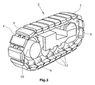
- Fig. 1 shows an embodiment of a track 2, which runs on replaceable wear pads 1.
- Such caterpillars are needed in the chassis of a tracked vehicle, such as a road construction machine.
- the wear pads 1 are releasably secured to base plates 4, wherein the base plates are in turn attached to chain links 6 of the endless circulating track 2.
- the track 2 runs with its chain links 6 to two pulleys 8 and 10, one of which is driven.
- several support rollers 12 are arranged, which carry the weight of the machine and run on the chain links.
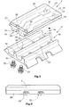
- Fig. 2 shows the wear pad 1 in a perspective view with the underlying base plate 4 and two of the four fastening screws 20 in total for attaching the replaceable wear pad 1 on the base plate 4th
- the wear pad 1 is preferably made of an elastomeric material, e.g. Polyurethane, which is colored according to a particularly preferred embodiment with a bright luminous color, preferably signal yellow.
- an elastomeric material e.g. Polyurethane
- the wear pad 1 has cast-in reinforcing elements 18, which preferably extend in the longitudinal direction of the wear pad 1.
- two such reinforcing elements 18 are arranged at a lateral distance from each other in the wear pad 1.
- the reinforcing elements 18 are provided with holes 22, with the aid of which after the production of the wear pad 1 fastener 26 can be anchored in the holes.
- the wear pads 1 have on their outer side a running surface 14, and one of the base plate 4 facing bottom 16.
- recesses 30 extend in the direction of the tread 14, which serve to receive fastening means.
- the recesses 30 are coaxial with the holes 22 of the reinforcing element 18. These recesses 30 are adapted to the fasteners to be used.
- the fastening means may consist of blind rivet nuts 26 or insert nuts 28, wherein the insert nuts 28 have both an internal thread and an external thread.
- the fasteners 26,28 are adapted to receive from the bottom 16 of the wear pad ago screwed fastening screws 20, as in Fig. 2 indicated.
- the base plates 4 on suitable through holes 32 which extend coaxially with the fastening means 26,28 and the holes 22 of the wear pad 1. It is essential that the fastening means 26,28 in the assembled state of the wear pads 1 rest directly on the base plate 4.
- the two reinforcing elements 18 in the wear pad 1 extend in the embodiment in on the underside 16 of the wear pad 1 projecting mutually parallel projections 36,38, which leave a gap 40 between them.
- the gap 40 between the projections 36,38 cooperates with a central web 42 of the base plate 4 such that the central web 42 forms a seat for the gap 40 between the projections 36,38 and the central web 42 of the base plate 4, the wear pad 1 substantially free of play the crawler 2 can center.
- a tight fit can be selected so that the wear pad 1 is seated on the base plate 4 substantially free of play.
- the projections 36,38 lie in channels 44,46 on the base plate 4 and can be supported there. However, the outer flanks of the projections 36,38 have a sufficient clearance with the outer side edges of the channels 44,46, so that only the central web 42 of the base plate 4 performs a centering of the wear pad 1.
- the extending in the longitudinal direction of the wear pad 1 projections 36,38 are interrupted by two transverse recesses 48,50, which provide a clearance for screw heads of fasteners that connect the base plate 4 through the through holes 52 with the chain links 6. These fasteners are therefore as best out Fig. 6 Removable covered by the wear pad 1 in the assembled state and are not added or damaged with road material.
- the strip-shaped reinforcing elements 18 extend in the region of the recesses 48,50 in a plane parallel to the tread 14 level.
- Fig. 3 shows the wear pad 1 mounted on the base plate 4 in a plane passing through the axes of the holes 22.
- blind rivet nuts 26 which are fixedly secured to the reinforcing elements 18 in the holes 22 by forming a formed by the riveting annular bead 56 to the reinforcing elements 18.
- the Blindnietmuttern 26 are preferably on a bearing collar 27 on the base plate 4.
- FIGS. 4a to 4d show various ways to design the recesses 30 for receiving fasteners 26,28.
- a mandrel 62,64 and 66 protrudes.
- the tool mold 60 points at a wear pad 1 according to Fig. 2 four such spines 62,64,66.
- the reinforcing elements 18 are placed with their holes 22 on the mandrels 62,64,66, wherein the reinforcing elements 18 rest on an annular collar 70 which is adapted in its shape to the stop collar 27 of the blind rivet nut 26 or the insert nut 28.
- the mandrel 62 is circular cylindrical.
- the mandrel 64 is hexagonal in cross-section and may be inserted in a hexagonal hole 22 of the reinforcing element 18.
- the mandrel 64 is extended by an example cylindrical projection 72, which extends beyond the length of a blind rivet nut 26 or an insert nut 28. This creates additional space for the free end of a fastening screw 20.
- the projection 72 may alternatively have a different cross-sectional shape.
- annular sleeve 74 made of an elastic material, such as foam rubber, placed.
- This elastic sleeve 74 which is seated directly on the reinforcing element 18, forms after completion of the wear pad 1, a soft annular zone on the tread 14 facing side of the reinforcing elements 18 such that the self-riveting process forming annular bead 56 of the blind rivet nut 26 in its deformation not hindered.
- Fig. 5 shows the use of an insert nut 28 as a fastener.
- the insert nut 28 is provided with an outer and an inner thread, so that the insert nut 28 can be screwed into the holes 22 of a reinforcing element 18 when the holes 22 are formed as threaded holes.
- the insert nut can have a self-tapping or self-tapping external thread which, when screwed into the holes 22 itself, produces a thread in the holes 22.
Landscapes
- Engineering & Computer Science (AREA)
- Chemical & Material Sciences (AREA)
- Combustion & Propulsion (AREA)
- Transportation (AREA)
- Mechanical Engineering (AREA)
- Connection Of Plates (AREA)
- Tires In General (AREA)
- Railway Tracks (AREA)
- Component Parts Of Construction Machinery (AREA)
Applications Claiming Priority (1)
| Application Number | Priority Date | Filing Date | Title |
|---|---|---|---|
| DE102006043763.2A DE102006043763C5 (de) | 2006-09-13 | 2006-09-13 | Auswechselbares Verschleißpolster, sowie Gleiskette |
Publications (3)
| Publication Number | Publication Date |
|---|---|
| EP1900621A2 EP1900621A2 (de) | 2008-03-19 |
| EP1900621A3 EP1900621A3 (de) | 2008-09-17 |
| EP1900621B1 true EP1900621B1 (de) | 2016-11-16 |
Family
ID=38829653
Family Applications (1)
| Application Number | Title | Priority Date | Filing Date |
|---|---|---|---|
| EP07115305.0A Active EP1900621B1 (de) | 2006-09-13 | 2007-08-30 | Auswechselbares Verschleißpolster, sowie Verfahren zur Herstellung von Verschleißpolstern für eine Gleiskette |
Country Status (8)
| Country | Link |
|---|---|
| US (1) | US7731306B2 (enExample) |
| EP (1) | EP1900621B1 (enExample) |
| JP (1) | JP5048426B2 (enExample) |
| KR (1) | KR100905154B1 (enExample) |
| CN (1) | CN101143605B (enExample) |
| AU (1) | AU2007214349B2 (enExample) |
| DE (1) | DE102006043763C5 (enExample) |
| TW (1) | TWI340704B (enExample) |
Families Citing this family (18)
| Publication number | Priority date | Publication date | Assignee | Title |
|---|---|---|---|---|
| US8011739B2 (en) * | 2006-09-13 | 2011-09-06 | Wirtgen Gmbh | Replaceable wear pad |
| EP2310250B1 (de) * | 2008-07-28 | 2011-12-07 | GMT Gummi-Metall-Technik GmbH | Kettenpolster für ein kettenglied |
| AU2009282143B2 (en) * | 2008-08-13 | 2013-06-20 | Caterpillar Global Mining America Llc | Crawler track having replaceable caulks |
| US20110148187A1 (en) * | 2009-12-18 | 2011-06-23 | Scott Francis Lyons | Replaceable Track Pad and Mounting Plate |
| CA2744680C (en) * | 2010-06-29 | 2016-10-04 | Robert Handfield | Slide bar for a track system |
| US8347702B2 (en) | 2010-08-04 | 2013-01-08 | The Pullman Company | Tracked vehicle track backer pad and road wheel tire test machine and method |
| DE102012012618B4 (de) | 2012-06-19 | 2014-05-22 | Bomag Gmbh | Gleiskette mit Lichtquelle, Verschleißplatte für eine solche Gleiskette, Verwendung einer Lichtquelle in einer Gleiskette sowie Baumaschine mit einer solchen Gleiskette |
| US20140306516A1 (en) * | 2013-04-16 | 2014-10-16 | Caterpillar Inc. | Vibration-damped track shoe for mobile machine |
| JP6820167B2 (ja) * | 2015-07-30 | 2021-01-27 | マニタウォック クレイン カンパニーズ, エルエルシーManitowoc Crane Companies, Llc | 伸縮式ブーム組立体のための分節型追従性摩耗パッド |
| CN105644641A (zh) * | 2016-02-04 | 2016-06-08 | 苏州凯通工程机械有限公司 | 履带耐磨组件 |
| DE102016202626A1 (de) | 2016-02-19 | 2017-08-24 | Wirtgen Gmbh | Verschleißpolster für eine Gleiskette eines Kettenfahrzeugs, Gleiskette und Baumaschine |
| US10308298B2 (en) * | 2016-04-20 | 2019-06-04 | Everpads Co., Ltd. | Track shoe pad structure assembly |
| US11111115B2 (en) | 2017-03-02 | 2021-09-07 | Maniitowoc Crane Companies, LLC | Wear pad with insert for telescoping boom assembly |
| US11370500B2 (en) * | 2018-09-17 | 2022-06-28 | Gallagher Corporation | Polyurethane wear pad |
| TWM581078U (zh) * | 2019-03-29 | 2019-07-21 | 永沛得股份有限公司 | 履帶板組及履帶膠塊內置件結構 |
| CN110450875B (zh) * | 2019-08-16 | 2020-07-28 | 浙江永鼎机械科技股份有限公司 | 一种车辆用履带 |
| US11878750B2 (en) * | 2020-01-17 | 2024-01-23 | Caterpillar Inc. | Wear inserts cast in a wear surface of a drive component |
| DE102022211813A1 (de) | 2022-11-08 | 2024-05-08 | Bomag Gmbh | VERSCHLEIßPOLSTER FÜR EIN LAUFFLÄCHENGLIED EINER GLEISKETTE EINES KETTENLAUF-WERKS EINER BAUMASCHINE, LAUFFLÄCHENGLIED FÜR EINE GLEISKETTE, GLEISKETTE FÜR EIN KETTENLAUFWERK EINER BAUMASCHINE, BAUMASCHINE SOWIE VERFAHREN ZUM ÜBERTRAGEN VON AUFSTANDSKRÄFTEN EINER BAUMASCHINE IN EINE BASISPLATTE EINES LAUFFLÄCHENGLIEDS |
Citations (1)
| Publication number | Priority date | Publication date | Assignee | Title |
|---|---|---|---|---|
| JP2005119365A (ja) * | 2003-10-14 | 2005-05-12 | Hitachi Constr Mach Co Ltd | 建設機械の履帯 |
Family Cites Families (24)
| Publication number | Priority date | Publication date | Assignee | Title |
|---|---|---|---|---|
| US638326A (en) * | 1899-04-08 | 1899-12-05 | Edward L Farr | Printing-machine for oil-cloth, linoleum, & c. |
| DE4100709A1 (de) * | 1991-01-11 | 1992-07-16 | Emhart Inc | Blindnietmutter mit zugdorn |
| JPH05278646A (ja) * | 1992-03-31 | 1993-10-26 | Hitachi Constr Mach Co Ltd | ゴムパッド付き履帯 |
| US5388900A (en) * | 1992-07-15 | 1995-02-14 | Kabushiki Kaisha Suzuki Shoji | Crawler pad |
| JPH06316280A (ja) * | 1993-04-30 | 1994-11-15 | Fukuyama Rubber Kogyo Kk | 連結リンク式ゴムクローラ |
| US5630657A (en) * | 1993-11-20 | 1997-05-20 | Bridgestone Corporation | Crawler |
| JPH07291159A (ja) * | 1994-03-02 | 1995-11-07 | Jonan Drive Center:Kk | 装軌式車両の履帯用ゴムパッド |
| JPH0853080A (ja) * | 1994-08-10 | 1996-02-27 | Suzuki Shoji:Kk | 履帯用パッド |
| JP3618823B2 (ja) * | 1995-04-07 | 2005-02-09 | 住友ゴム工業株式会社 | 金属製クローラの履板用弾性パッド |
| JPH0930461A (ja) * | 1995-07-20 | 1997-02-04 | Suzuki Shoji:Kk | 履帯用パッド |
| JPH09301233A (ja) | 1996-05-20 | 1997-11-25 | Yutani Heavy Ind Ltd | 鉄クローラのゴムパッド取付構造 |
| JPH1016837A (ja) * | 1996-07-01 | 1998-01-20 | Bridgestone Corp | クロ−ラ用弾性シュ− |
| JPH1067353A (ja) | 1996-08-28 | 1998-03-10 | Bridgestone Corp | 車輪又は無限軌道帯装着用セグメント |
| JPH10114286A (ja) * | 1996-10-09 | 1998-05-06 | Suzuki Shoji:Kk | 履帯用パッド |
| JPH10157666A (ja) * | 1996-11-26 | 1998-06-16 | Suzuki Shoji:Kk | 履帯用パッド |
| JPH11245862A (ja) * | 1998-03-01 | 1999-09-14 | Bridgestone Corp | 後付け用ゴムパッド |
| JPH11286284A (ja) | 1998-04-01 | 1999-10-19 | Fukuyama Rubber Kogyo Kk | 脱着式パッド |
| JP2002293276A (ja) * | 2001-03-31 | 2002-10-09 | Suzuki Shoji:Kk | 履帯用パッド |
| JP2002321670A (ja) * | 2001-04-27 | 2002-11-05 | Mitsubishi Steel Mfg Co Ltd | 履帯用シュー |
| JP4675522B2 (ja) * | 2001-09-04 | 2011-04-27 | 住友ゴム工業株式会社 | 弾性パッド |
| JP3901505B2 (ja) * | 2001-12-17 | 2007-04-04 | 株式会社小松製作所 | 弾性体履板 |
| JP2004136753A (ja) * | 2002-10-17 | 2004-05-13 | Mitsubishi Steel Mfg Co Ltd | 履帯用ゴムパッド |
| DE102004003240A1 (de) * | 2004-01-21 | 2005-08-11 | Newfrey Llc, Newark | Blindnietmutter |
| JP2006224785A (ja) * | 2005-02-17 | 2006-08-31 | Mitsubishi Steel Mfg Co Ltd | 覆帯用ゴムパッド |
-
2006
- 2006-09-13 DE DE102006043763.2A patent/DE102006043763C5/de active Active
-
2007
- 2007-08-30 EP EP07115305.0A patent/EP1900621B1/de active Active
- 2007-08-31 AU AU2007214349A patent/AU2007214349B2/en not_active Ceased
- 2007-09-07 TW TW096133326A patent/TWI340704B/zh not_active IP Right Cessation
- 2007-09-10 KR KR1020070091369A patent/KR100905154B1/ko not_active Expired - Fee Related
- 2007-09-11 US US11/898,249 patent/US7731306B2/en active Active
- 2007-09-12 JP JP2007236234A patent/JP5048426B2/ja not_active Expired - Fee Related
- 2007-09-12 CN CN2007101495707A patent/CN101143605B/zh active Active
Patent Citations (1)
| Publication number | Priority date | Publication date | Assignee | Title |
|---|---|---|---|---|
| JP2005119365A (ja) * | 2003-10-14 | 2005-05-12 | Hitachi Constr Mach Co Ltd | 建設機械の履帯 |
Also Published As
| Publication number | Publication date |
|---|---|
| CN101143605B (zh) | 2010-09-22 |
| DE102006043763C5 (de) | 2020-07-16 |
| TWI340704B (en) | 2011-04-21 |
| DE102006043763A1 (de) | 2008-03-27 |
| US20080061626A1 (en) | 2008-03-13 |
| JP2008074394A (ja) | 2008-04-03 |
| DE102006043763B4 (de) | 2012-11-29 |
| JP5048426B2 (ja) | 2012-10-17 |
| KR20080024977A (ko) | 2008-03-19 |
| US7731306B2 (en) | 2010-06-08 |
| AU2007214349B2 (en) | 2010-05-13 |
| TW200823097A (en) | 2008-06-01 |
| AU2007214349A1 (en) | 2008-04-03 |
| KR100905154B1 (ko) | 2009-06-29 |
| EP1900621A3 (de) | 2008-09-17 |
| EP1900621A2 (de) | 2008-03-19 |
| CN101143605A (zh) | 2008-03-19 |
Similar Documents
| Publication | Publication Date | Title |
|---|---|---|
| EP1900621B1 (de) | Auswechselbares Verschleißpolster, sowie Verfahren zur Herstellung von Verschleißpolstern für eine Gleiskette | |
| DE2437809C3 (de) | Siebboden sowie Siebkörper und Rahmen hierfür | |
| DE19949545B4 (de) | Zahnriemen zum Transportieren von Objekten | |
| WO2015032674A1 (de) | Palette für einen fahrsteig oder stufe für eine fahrtreppe | |
| WO2015058909A1 (de) | Befestigungsvorrichtung zum befestigen einer stufe oder palette an einem zugmittel | |
| EP3416876B1 (de) | Verschleisspolster für eine gleiskette eines kettenfahrzeugs, gleiskette und baumaschine | |
| DE2607154A1 (de) | Flanschverbindung fuer rahmen o.dgl. | |
| DE3008287A1 (de) | Bolzen fuer schubstangen | |
| DE60119692T2 (de) | Bandraupe und ihr Herstellungsverfahren | |
| EP2918482B1 (de) | Traktionskette für eine Raupenkette eines Kettenfahrzeugs sowie Bausatz für eine Raupenkette | |
| CH672103A5 (enExample) | ||
| AT524130B1 (de) | Steighilfe | |
| AT500252B1 (de) | Gleitbrett, insbesondere ski | |
| EP0120996A1 (de) | Fördervorrichtung | |
| DE102014200486B3 (de) | Stützwinde | |
| DE4314186C1 (de) | Fahrbahnübergang | |
| EP2933140A2 (de) | Sicherungsschiene zum einbau in fahrzeuge | |
| DE2817768A1 (de) | Verstaebungen | |
| AT525915B1 (de) | Traktionshilfe | |
| WO2022135860A1 (de) | Schienenbefestigungsvorrichtung für führungsschienenabschnitte einer fahrtreppe oder eines fahrsteiges | |
| DE2914127B1 (de) | Kettenrad,insbesondere Antriebsrad fuer Gleiskettenfahrzeuge | |
| EP3798108A1 (de) | Kettenanordnung für eine pistenraupe | |
| DE202008017524U1 (de) | Anbauelement zum Festlegen in einer oder mehreren T-Nuten | |
| DE102020208735A1 (de) | Laufwerkskette für ein Kettenfahrzeug | |
| EP4088994B1 (de) | Gleitschutzvorrichtung |
Legal Events
| Date | Code | Title | Description |
|---|---|---|---|
| PUAI | Public reference made under article 153(3) epc to a published international application that has entered the european phase |
Free format text: ORIGINAL CODE: 0009012 |
|
| AK | Designated contracting states |
Kind code of ref document: A2 Designated state(s): AT BE BG CH CY CZ DE DK EE ES FI FR GB GR HU IE IS IT LI LT LU LV MC MT NL PL PT RO SE SI SK TR |
|
| AX | Request for extension of the european patent |
Extension state: AL BA HR MK YU |
|
| RIC1 | Information provided on ipc code assigned before grant |
Ipc: B62D 55/275 20060101AFI20080103BHEP Ipc: B62D 55/28 20060101ALI20080528BHEP |
|
| PUAL | Search report despatched |
Free format text: ORIGINAL CODE: 0009013 |
|
| AK | Designated contracting states |
Kind code of ref document: A3 Designated state(s): AT BE BG CH CY CZ DE DK EE ES FI FR GB GR HU IE IS IT LI LT LU LV MC MT NL PL PT RO SE SI SK TR |
|
| AX | Request for extension of the european patent |
Extension state: AL BA HR MK RS |
|
| 17P | Request for examination filed |
Effective date: 20090316 |
|
| AKX | Designation fees paid |
Designated state(s): AT BE BG CH CY CZ DE DK EE ES FI FR GB GR HU IE IS IT LI LT LU LV MC MT NL PL PT RO SE SI SK TR |
|
| 17Q | First examination report despatched |
Effective date: 20111122 |
|
| TPAC | Observations filed by third parties |
Free format text: ORIGINAL CODE: EPIDOSNTIPA |
|
| RAP1 | Party data changed (applicant data changed or rights of an application transferred) |
Owner name: WIRTGEN GMBH |
|
| GRAP | Despatch of communication of intention to grant a patent |
Free format text: ORIGINAL CODE: EPIDOSNIGR1 |
|
| INTG | Intention to grant announced |
Effective date: 20160527 |
|
| GRAS | Grant fee paid |
Free format text: ORIGINAL CODE: EPIDOSNIGR3 |
|
| GRAA | (expected) grant |
Free format text: ORIGINAL CODE: 0009210 |
|
| AK | Designated contracting states |
Kind code of ref document: B1 Designated state(s): AT BE BG CH CY CZ DE DK EE ES FI FR GB GR HU IE IS IT LI LT LU LV MC MT NL PL PT RO SE SI SK TR |
|
| REG | Reference to a national code |
Ref country code: GB Ref legal event code: FG4D Free format text: NOT ENGLISH |
|
| REG | Reference to a national code |
Ref country code: CH Ref legal event code: EP |
|
| REG | Reference to a national code |
Ref country code: IE Ref legal event code: FG4D Free format text: LANGUAGE OF EP DOCUMENT: GERMAN |
|
| REG | Reference to a national code |
Ref country code: AT Ref legal event code: REF Ref document number: 845631 Country of ref document: AT Kind code of ref document: T Effective date: 20161215 |
|
| REG | Reference to a national code |
Ref country code: DE Ref legal event code: R096 Ref document number: 502007015258 Country of ref document: DE |
|
| PG25 | Lapsed in a contracting state [announced via postgrant information from national office to epo] |
Ref country code: LV Free format text: LAPSE BECAUSE OF FAILURE TO SUBMIT A TRANSLATION OF THE DESCRIPTION OR TO PAY THE FEE WITHIN THE PRESCRIBED TIME-LIMIT Effective date: 20161116 |
|
| REG | Reference to a national code |
Ref country code: NL Ref legal event code: MP Effective date: 20161116 |
|
| REG | Reference to a national code |
Ref country code: LT Ref legal event code: MG4D |
|
| PG25 | Lapsed in a contracting state [announced via postgrant information from national office to epo] |
Ref country code: LT Free format text: LAPSE BECAUSE OF FAILURE TO SUBMIT A TRANSLATION OF THE DESCRIPTION OR TO PAY THE FEE WITHIN THE PRESCRIBED TIME-LIMIT Effective date: 20161116 Ref country code: SE Free format text: LAPSE BECAUSE OF FAILURE TO SUBMIT A TRANSLATION OF THE DESCRIPTION OR TO PAY THE FEE WITHIN THE PRESCRIBED TIME-LIMIT Effective date: 20161116 Ref country code: GR Free format text: LAPSE BECAUSE OF FAILURE TO SUBMIT A TRANSLATION OF THE DESCRIPTION OR TO PAY THE FEE WITHIN THE PRESCRIBED TIME-LIMIT Effective date: 20170217 Ref country code: NL Free format text: LAPSE BECAUSE OF FAILURE TO SUBMIT A TRANSLATION OF THE DESCRIPTION OR TO PAY THE FEE WITHIN THE PRESCRIBED TIME-LIMIT Effective date: 20161116 |
|
| PG25 | Lapsed in a contracting state [announced via postgrant information from national office to epo] |
Ref country code: PL Free format text: LAPSE BECAUSE OF FAILURE TO SUBMIT A TRANSLATION OF THE DESCRIPTION OR TO PAY THE FEE WITHIN THE PRESCRIBED TIME-LIMIT Effective date: 20161116 Ref country code: PT Free format text: LAPSE BECAUSE OF FAILURE TO SUBMIT A TRANSLATION OF THE DESCRIPTION OR TO PAY THE FEE WITHIN THE PRESCRIBED TIME-LIMIT Effective date: 20170316 Ref country code: ES Free format text: LAPSE BECAUSE OF FAILURE TO SUBMIT A TRANSLATION OF THE DESCRIPTION OR TO PAY THE FEE WITHIN THE PRESCRIBED TIME-LIMIT Effective date: 20161116 Ref country code: FI Free format text: LAPSE BECAUSE OF FAILURE TO SUBMIT A TRANSLATION OF THE DESCRIPTION OR TO PAY THE FEE WITHIN THE PRESCRIBED TIME-LIMIT Effective date: 20161116 |
|
| PG25 | Lapsed in a contracting state [announced via postgrant information from national office to epo] |
Ref country code: RO Free format text: LAPSE BECAUSE OF FAILURE TO SUBMIT A TRANSLATION OF THE DESCRIPTION OR TO PAY THE FEE WITHIN THE PRESCRIBED TIME-LIMIT Effective date: 20161116 Ref country code: CZ Free format text: LAPSE BECAUSE OF FAILURE TO SUBMIT A TRANSLATION OF THE DESCRIPTION OR TO PAY THE FEE WITHIN THE PRESCRIBED TIME-LIMIT Effective date: 20161116 Ref country code: DK Free format text: LAPSE BECAUSE OF FAILURE TO SUBMIT A TRANSLATION OF THE DESCRIPTION OR TO PAY THE FEE WITHIN THE PRESCRIBED TIME-LIMIT Effective date: 20161116 Ref country code: SK Free format text: LAPSE BECAUSE OF FAILURE TO SUBMIT A TRANSLATION OF THE DESCRIPTION OR TO PAY THE FEE WITHIN THE PRESCRIBED TIME-LIMIT Effective date: 20161116 Ref country code: EE Free format text: LAPSE BECAUSE OF FAILURE TO SUBMIT A TRANSLATION OF THE DESCRIPTION OR TO PAY THE FEE WITHIN THE PRESCRIBED TIME-LIMIT Effective date: 20161116 |
|
| REG | Reference to a national code |
Ref country code: DE Ref legal event code: R097 Ref document number: 502007015258 Country of ref document: DE |
|
| REG | Reference to a national code |
Ref country code: FR Ref legal event code: PLFP Year of fee payment: 11 |
|
| PG25 | Lapsed in a contracting state [announced via postgrant information from national office to epo] |
Ref country code: IT Free format text: LAPSE BECAUSE OF FAILURE TO SUBMIT A TRANSLATION OF THE DESCRIPTION OR TO PAY THE FEE WITHIN THE PRESCRIBED TIME-LIMIT Effective date: 20161116 Ref country code: BG Free format text: LAPSE BECAUSE OF FAILURE TO SUBMIT A TRANSLATION OF THE DESCRIPTION OR TO PAY THE FEE WITHIN THE PRESCRIBED TIME-LIMIT Effective date: 20170216 |
|
| PLBE | No opposition filed within time limit |
Free format text: ORIGINAL CODE: 0009261 |
|
| STAA | Information on the status of an ep patent application or granted ep patent |
Free format text: STATUS: NO OPPOSITION FILED WITHIN TIME LIMIT |
|
| 26N | No opposition filed |
Effective date: 20170817 |
|
| PG25 | Lapsed in a contracting state [announced via postgrant information from national office to epo] |
Ref country code: SI Free format text: LAPSE BECAUSE OF FAILURE TO SUBMIT A TRANSLATION OF THE DESCRIPTION OR TO PAY THE FEE WITHIN THE PRESCRIBED TIME-LIMIT Effective date: 20161116 |
|
| REG | Reference to a national code |
Ref country code: CH Ref legal event code: PL |
|
| PG25 | Lapsed in a contracting state [announced via postgrant information from national office to epo] |
Ref country code: MC Free format text: LAPSE BECAUSE OF FAILURE TO SUBMIT A TRANSLATION OF THE DESCRIPTION OR TO PAY THE FEE WITHIN THE PRESCRIBED TIME-LIMIT Effective date: 20161116 |
|
| PG25 | Lapsed in a contracting state [announced via postgrant information from national office to epo] |
Ref country code: LI Free format text: LAPSE BECAUSE OF NON-PAYMENT OF DUE FEES Effective date: 20170831 Ref country code: CH Free format text: LAPSE BECAUSE OF NON-PAYMENT OF DUE FEES Effective date: 20170831 |
|
| REG | Reference to a national code |
Ref country code: IE Ref legal event code: MM4A |
|
| REG | Reference to a national code |
Ref country code: BE Ref legal event code: MM Effective date: 20170831 |
|
| PG25 | Lapsed in a contracting state [announced via postgrant information from national office to epo] |
Ref country code: LU Free format text: LAPSE BECAUSE OF NON-PAYMENT OF DUE FEES Effective date: 20170830 |
|
| PG25 | Lapsed in a contracting state [announced via postgrant information from national office to epo] |
Ref country code: IE Free format text: LAPSE BECAUSE OF NON-PAYMENT OF DUE FEES Effective date: 20170830 |
|
| REG | Reference to a national code |
Ref country code: FR Ref legal event code: PLFP Year of fee payment: 12 |
|
| PG25 | Lapsed in a contracting state [announced via postgrant information from national office to epo] |
Ref country code: BE Free format text: LAPSE BECAUSE OF NON-PAYMENT OF DUE FEES Effective date: 20170831 |
|
| PG25 | Lapsed in a contracting state [announced via postgrant information from national office to epo] |
Ref country code: MT Free format text: LAPSE BECAUSE OF FAILURE TO SUBMIT A TRANSLATION OF THE DESCRIPTION OR TO PAY THE FEE WITHIN THE PRESCRIBED TIME-LIMIT Effective date: 20161116 |
|
| REG | Reference to a national code |
Ref country code: AT Ref legal event code: MM01 Ref document number: 845631 Country of ref document: AT Kind code of ref document: T Effective date: 20170830 |
|
| PG25 | Lapsed in a contracting state [announced via postgrant information from national office to epo] |
Ref country code: AT Free format text: LAPSE BECAUSE OF NON-PAYMENT OF DUE FEES Effective date: 20170830 |
|
| PG25 | Lapsed in a contracting state [announced via postgrant information from national office to epo] |
Ref country code: HU Free format text: LAPSE BECAUSE OF FAILURE TO SUBMIT A TRANSLATION OF THE DESCRIPTION OR TO PAY THE FEE WITHIN THE PRESCRIBED TIME-LIMIT; INVALID AB INITIO Effective date: 20070830 |
|
| PG25 | Lapsed in a contracting state [announced via postgrant information from national office to epo] |
Ref country code: CY Free format text: LAPSE BECAUSE OF NON-PAYMENT OF DUE FEES Effective date: 20161116 |
|
| PG25 | Lapsed in a contracting state [announced via postgrant information from national office to epo] |
Ref country code: TR Free format text: LAPSE BECAUSE OF FAILURE TO SUBMIT A TRANSLATION OF THE DESCRIPTION OR TO PAY THE FEE WITHIN THE PRESCRIBED TIME-LIMIT Effective date: 20161116 |
|
| PG25 | Lapsed in a contracting state [announced via postgrant information from national office to epo] |
Ref country code: IS Free format text: LAPSE BECAUSE OF FAILURE TO SUBMIT A TRANSLATION OF THE DESCRIPTION OR TO PAY THE FEE WITHIN THE PRESCRIBED TIME-LIMIT Effective date: 20170316 |
|
| P01 | Opt-out of the competence of the unified patent court (upc) registered |
Effective date: 20230525 |
|
| PGFP | Annual fee paid to national office [announced via postgrant information from national office to epo] |
Ref country code: DE Payment date: 20250819 Year of fee payment: 19 |
|
| PGFP | Annual fee paid to national office [announced via postgrant information from national office to epo] |
Ref country code: GB Payment date: 20250822 Year of fee payment: 19 |
|
| PGFP | Annual fee paid to national office [announced via postgrant information from national office to epo] |
Ref country code: FR Payment date: 20250821 Year of fee payment: 19 |