EP1898504A1 - Lichtquelle - Google Patents
Lichtquelle Download PDFInfo
- Publication number
- EP1898504A1 EP1898504A1 EP06766474A EP06766474A EP1898504A1 EP 1898504 A1 EP1898504 A1 EP 1898504A1 EP 06766474 A EP06766474 A EP 06766474A EP 06766474 A EP06766474 A EP 06766474A EP 1898504 A1 EP1898504 A1 EP 1898504A1
- Authority
- EP
- European Patent Office
- Prior art keywords
- light
- output
- light source
- waveguide
- source according
- Prior art date
- Legal status (The legal status is an assumption and is not a legal conclusion. Google has not performed a legal analysis and makes no representation as to the accuracy of the status listed.)
- Withdrawn
Links
Images


Classifications
-
- H—ELECTRICITY
- H01—ELECTRIC ELEMENTS
- H01S—DEVICES USING THE PROCESS OF LIGHT AMPLIFICATION BY STIMULATED EMISSION OF RADIATION [LASER] TO AMPLIFY OR GENERATE LIGHT; DEVICES USING STIMULATED EMISSION OF ELECTROMAGNETIC RADIATION IN WAVE RANGES OTHER THAN OPTICAL
- H01S3/00—Lasers, i.e. devices using stimulated emission of electromagnetic radiation in the infrared, visible or ultraviolet wave range
- H01S3/09—Processes or apparatus for excitation, e.g. pumping
- H01S3/091—Processes or apparatus for excitation, e.g. pumping using optical pumping
- H01S3/094—Processes or apparatus for excitation, e.g. pumping using optical pumping by coherent light
- H01S3/0941—Processes or apparatus for excitation, e.g. pumping using optical pumping by coherent light of a laser diode
- H01S3/09415—Processes or apparatus for excitation, e.g. pumping using optical pumping by coherent light of a laser diode the pumping beam being parallel to the lasing mode of the pumped medium, e.g. end-pumping
-
- G—PHYSICS
- G02—OPTICS
- G02B—OPTICAL ELEMENTS, SYSTEMS OR APPARATUS
- G02B6/00—Light guides; Structural details of arrangements comprising light guides and other optical elements, e.g. couplings
- G02B6/24—Coupling light guides
- G02B6/26—Optical coupling means
- G02B6/28—Optical coupling means having data bus means, i.e. plural waveguides interconnected and providing an inherently bidirectional system by mixing and splitting signals
- G02B6/293—Optical coupling means having data bus means, i.e. plural waveguides interconnected and providing an inherently bidirectional system by mixing and splitting signals with wavelength selective means
- G02B6/29346—Optical coupling means having data bus means, i.e. plural waveguides interconnected and providing an inherently bidirectional system by mixing and splitting signals with wavelength selective means operating by wave or beam interference
- G02B6/29358—Multiple beam interferometer external to a light guide, e.g. Fabry-Pérot, etalon, VIPA plate, OTDL plate, continuous interferometer, parallel plate resonator
-
- H—ELECTRICITY
- H01—ELECTRIC ELEMENTS
- H01S—DEVICES USING THE PROCESS OF LIGHT AMPLIFICATION BY STIMULATED EMISSION OF RADIATION [LASER] TO AMPLIFY OR GENERATE LIGHT; DEVICES USING STIMULATED EMISSION OF ELECTROMAGNETIC RADIATION IN WAVE RANGES OTHER THAN OPTICAL
- H01S3/00—Lasers, i.e. devices using stimulated emission of electromagnetic radiation in the infrared, visible or ultraviolet wave range
- H01S3/05—Construction or shape of optical resonators; Accommodation of active medium therein; Shape of active medium
- H01S3/06—Construction or shape of active medium
- H01S3/063—Waveguide lasers, i.e. whereby the dimensions of the waveguide are of the order of the light wavelength
- H01S3/067—Fibre lasers
- H01S3/06708—Constructional details of the fibre, e.g. compositions, cross-section, shape or tapering
-
- H—ELECTRICITY
- H01—ELECTRIC ELEMENTS
- H01S—DEVICES USING THE PROCESS OF LIGHT AMPLIFICATION BY STIMULATED EMISSION OF RADIATION [LASER] TO AMPLIFY OR GENERATE LIGHT; DEVICES USING STIMULATED EMISSION OF ELECTROMAGNETIC RADIATION IN WAVE RANGES OTHER THAN OPTICAL
- H01S3/00—Lasers, i.e. devices using stimulated emission of electromagnetic radiation in the infrared, visible or ultraviolet wave range
- H01S3/05—Construction or shape of optical resonators; Accommodation of active medium therein; Shape of active medium
- H01S3/06—Construction or shape of active medium
- H01S3/063—Waveguide lasers, i.e. whereby the dimensions of the waveguide are of the order of the light wavelength
- H01S3/067—Fibre lasers
- H01S3/0675—Resonators including a grating structure, e.g. distributed Bragg reflectors [DBR] or distributed feedback [DFB] fibre lasers
-
- G—PHYSICS
- G01—MEASURING; TESTING
- G01N—INVESTIGATING OR ANALYSING MATERIALS BY DETERMINING THEIR CHEMICAL OR PHYSICAL PROPERTIES
- G01N2201/00—Features of devices classified in G01N21/00
- G01N2201/06—Illumination; Optics
- G01N2201/061—Sources
- G01N2201/06113—Coherent sources; lasers
-
- G—PHYSICS
- G02—OPTICS
- G02B—OPTICAL ELEMENTS, SYSTEMS OR APPARATUS
- G02B6/00—Light guides; Structural details of arrangements comprising light guides and other optical elements, e.g. couplings
- G02B6/24—Coupling light guides
- G02B6/26—Optical coupling means
- G02B6/28—Optical coupling means having data bus means, i.e. plural waveguides interconnected and providing an inherently bidirectional system by mixing and splitting signals
- G02B6/293—Optical coupling means having data bus means, i.e. plural waveguides interconnected and providing an inherently bidirectional system by mixing and splitting signals with wavelength selective means
- G02B6/29304—Optical coupling means having data bus means, i.e. plural waveguides interconnected and providing an inherently bidirectional system by mixing and splitting signals with wavelength selective means operating by diffraction, e.g. grating
- G02B6/29316—Light guides comprising a diffractive element, e.g. grating in or on the light guide such that diffracted light is confined in the light guide
- G02B6/29317—Light guides of the optical fibre type
-
- H—ELECTRICITY
- H01—ELECTRIC ELEMENTS
- H01S—DEVICES USING THE PROCESS OF LIGHT AMPLIFICATION BY STIMULATED EMISSION OF RADIATION [LASER] TO AMPLIFY OR GENERATE LIGHT; DEVICES USING STIMULATED EMISSION OF ELECTROMAGNETIC RADIATION IN WAVE RANGES OTHER THAN OPTICAL
- H01S3/00—Lasers, i.e. devices using stimulated emission of electromagnetic radiation in the infrared, visible or ultraviolet wave range
- H01S3/05—Construction or shape of optical resonators; Accommodation of active medium therein; Shape of active medium
- H01S3/08—Construction or shape of optical resonators or components thereof
- H01S3/08018—Mode suppression
- H01S3/08022—Longitudinal modes
- H01S3/08031—Single-mode emission
- H01S3/08036—Single-mode emission using intracavity dispersive, polarising or birefringent elements
-
- H—ELECTRICITY
- H01—ELECTRIC ELEMENTS
- H01S—DEVICES USING THE PROCESS OF LIGHT AMPLIFICATION BY STIMULATED EMISSION OF RADIATION [LASER] TO AMPLIFY OR GENERATE LIGHT; DEVICES USING STIMULATED EMISSION OF ELECTROMAGNETIC RADIATION IN WAVE RANGES OTHER THAN OPTICAL
- H01S3/00—Lasers, i.e. devices using stimulated emission of electromagnetic radiation in the infrared, visible or ultraviolet wave range
- H01S3/10—Controlling the intensity, frequency, phase, polarisation or direction of the emitted radiation, e.g. switching, gating, modulating or demodulating
- H01S3/106—Controlling the intensity, frequency, phase, polarisation or direction of the emitted radiation, e.g. switching, gating, modulating or demodulating by controlling devices placed within the cavity
- H01S3/1062—Controlling the intensity, frequency, phase, polarisation or direction of the emitted radiation, e.g. switching, gating, modulating or demodulating by controlling devices placed within the cavity using a controlled passive interferometer, e.g. a Fabry-Perot etalon
-
- H—ELECTRICITY
- H01—ELECTRIC ELEMENTS
- H01S—DEVICES USING THE PROCESS OF LIGHT AMPLIFICATION BY STIMULATED EMISSION OF RADIATION [LASER] TO AMPLIFY OR GENERATE LIGHT; DEVICES USING STIMULATED EMISSION OF ELECTROMAGNETIC RADIATION IN WAVE RANGES OTHER THAN OPTICAL
- H01S3/00—Lasers, i.e. devices using stimulated emission of electromagnetic radiation in the infrared, visible or ultraviolet wave range
- H01S3/14—Lasers, i.e. devices using stimulated emission of electromagnetic radiation in the infrared, visible or ultraviolet wave range characterised by the material used as the active medium
- H01S3/16—Solid materials
- H01S3/1601—Solid materials characterised by an active (lasing) ion
- H01S3/1603—Solid materials characterised by an active (lasing) ion rare earth
- H01S3/1618—Solid materials characterised by an active (lasing) ion rare earth ytterbium
Definitions
- the present invention relates to a light source that is used mainly for a laser microscope, a biomedical analyzer, and a precision measurement device.
- a light source used for, for example, a laser microscope, a fluorescence analyzer for biomedicine, a biological analyzer for biomedicine, and a precision measurement device includes a semiconductor laser or a light source that generates a harmonic light by pumping an SHG (second harmonic generation) element or a THG (third harmonic generation) element that serves as a harmonic generating element such as a nonlinear optical crystal with a semiconductor laser.
- a light generated by the semiconductor laser has a specific wavelength
- a harmonic light generated by the SHG element or the THG element has a wavelength of a half or a third of a wavelength of a semiconductor laser used for pumping.
- an optical fiber laser employing an optical fiber is disclosed as a light source that generates a light having a desired wavelength (for example, see Patent Document 1).
- Patent Document 1 Japanese Patent Application Laid-open No. 2005-12008
- a light having a wavelength between 530 nm and 600 nm is necessary to perform fluorescence analysis of protein.
- a light source that generates a light having a wavelength between 1060 nm and 1200 nm is necessary.
- a conventional light source has a problem that a light output is not stable enough.
- a light source used in combination with a harmonic generating element results in a problem that an output of a harmonic light generated by the harmonic generating element is unstable.
- the present invention is made in view of the above problem, and an object of the present invention is to provide a light source that realizes a stable light output.
- a light source includes a semiconductor pumping laser; a pumping-light waveguide that guides a pumping laser light output from the semiconductor pumping laser; an amplified-light waveguide that is connected to the pumping-light waveguide, the amplified-light waveguide being doped with an amplification medium that is pumped by the pumping laser light output from the pumping-light waveguide to generate a spontaneous emission light in a predetermined wavelength band; an output-light waveguide that guides the spontaneous emission light output from the amplified-light waveguide; a spatial coupling unit provided between the amplified-light waveguide and the output-light waveguide, which includes a wavelength selecting element that selectively transmits a light having a desired wavelength band out of the spontaneous emission light, and a lens unit that couples the spontaneous emission light to the wavelength selecting unit; an input-side light reflecting unit that is provided between the semiconductor pumping laser and the amplified-light waveguide; and an output-side light reflecting unit that is formed on an output
- the output-side light reflecting unit is a fiber Bragg grating formed on the output-light waveguide, and that selectively reflects a light in a wavelength band including a transmission wavelength of the wavelength selecting element.
- the output-side light reflecting unit is a filter formed on either one of an input facet and an output facet of the output-light waveguide.
- the input-side light reflecting unit is a filter formed on either one of an output facet of the pumping-light waveguide and an input facet of the amplified-light waveguide.
- the input-side light reflecting unit has a reflectivity equal to or higher than 95% at a transmission wavelength of the wavelength selecting element
- the output-side light reflecting unit has a reflectivity equal to or higher than 4% and equal to or lower than 70% at the transmission wavelength of the wavelength selecting element.
- the pumping-light waveguide is a multimode optical fiber having a core diameter equal to or larger than 50 ⁇ m and equal to or smaller than 400 ⁇ m.
- the amplified-light waveguide includes a core region doped with the amplification medium, an inner cladding layer that is formed on an outer circumference of the core region, and that has a refractive index smaller than a refractive index of the core region, and an outer cladding layer that is formed on an outer circumference of the inner cladding layer, and that has a refractive index smaller than the refractive index of the inner cladding layer.
- the pumping laser light propagates through the core region and the inner cladding layer and pumps the amplification medium that is doped into the core region, and the spontaneous emission light generated by pumped amplification medium propagates through the core region.
- the amplification medium is either one of ytterbium and erbium.
- At least one of an output facet of the pumping-light waveguide and an input facet of the amplified-light waveguide forms a concave surface having a depth of 50 ⁇ m at a center portion.
- the output-light waveguide is a polarization-maintaining optical fiber.
- the wavelength selecting element is either one of a dielectric multilayer filter and an etalon filter each having a full width half maximum of a transmission band equal to or narrower than 10 nm and a transmissivity equal to or higher than 70% at a center wavelength of the transmission band.
- the full width half maximum of the transmission band of the wavelength selecting element is equal to or narrower than 3 nm.
- the wavelength selecting element is arranged in such a manner that an inclination angle of the spatial coupling unit with respect to an optical axis is adjusted such that a center wavelength of the transmission band becomes a predetermined value.
- the lens unit is any one of a spherical lens, a plano-convex lens, a distributed refractive index lens, a graded-index optical fiber, and an aspherical lens.
- an antireflection coating is formed on either one of a surface of the distributed refractive index lens to which a light is input and a surface of the distributed refractive index lens from which the light is output.
- At least one of facets of the pumping-light waveguide, the amplified-light waveguide, and the output-light waveguide without having the input-side light reflecting unit or the output-side light reflecting unit has an angle of four degrees with respect to a plane perpendicular to an optical axis.
- an antireflection coating is formed on at least one of facets of the pumping-light waveguide, the amplified-light waveguide, and the output-light waveguide without having the input-side light reflecting unit or the output-side light reflecting unit.
- a reflection coating that reflects a light having the wavelength of the pumping laser light with a reflectivity equal to or higher than 4% and equal to or lower than 20% is formed on the output facet of the amplified-light waveguide.
- the spatial coupling unit includes a polarizer that transmits a light of the spontaneous emission light with a predetermined polarization.
- At least one end portion of the pumping-light waveguide and one end portion of the amplified-light waveguide among the pumping-light waveguide, the amplified-light waveguide, the spatial coupling unit, and the output-light waveguide are respectively held in ferrules of a cylindrical shape such that ends of the ferrules and the facets of the pumping-light waveguide and the amplified-light waveguide are on the same plane, and the pumping-light waveguide and the amplified-light waveguide are connected by inserting the ferrules into a sleeve having a through hole with a diameter same as an outer diameter of the ferrule from both ends of the sleeve and connecting the ends of the ferrules.
- an amplified-light waveguide and a laser resonator which includes a spatial coupling unit including a wavelength selecting element that selectively transmits a light having a desired wavelength band out of a spontaneous emission light generated in the amplified-light waveguide
- a stable laser oscillation with a wavelength of a light that can be transmitted through the wavelength selecting element can be obtained so that an unnecessary light having the wavelength band of the spontaneous emission light is filtered to avoid an unstable laser oscillation.
- FIG. 1 is a schematic diagram of a
- Fig. 1 is a schematic cross section of a light source according to a first embodiment of the present invention.
- the light source 100 includes a semiconductor pumping laser 1, a multimode optical fiber 2, a double-clad optical fiber 3, a single-mode optical fiber 4, a spatial coupling unit 10, a dielectric multilayer filter 7, and a dielectric multilayer filter 8.
- the multimode optical fiber 2 serving as a pumping-light waveguide guides a pumping laser light having a wavelength of 915 nm output from the semiconductor pumping laser 1.
- the double-clad optical fiber 3 serving as an amplified-light waveguide is connected to the multimode optical fiber 2 doped with Ytterbium (Yb) ions serving as an amplification medium that is pumped by the pumping laser light output from the multimode optical fiber 2 to generate a spontaneous emission light having a wavelength band between 1060 nm to 1200 nm.
- the single-mode optical fiber 4 serving as an output-light waveguide guides the spontaneous emission light output from the double-clad optical fiber 3.
- the spatial coupling unit 10 is provided between the double-clad optical fiber 3 and the single-mode optical fiber 4.
- the spatial coupling unit 10 includes etalon filters 6a and 6b serving as a wavelength selecting element that selectively transmits a light of a desired wavelength from the spontaneous emission light, a light having a center wavelength of 1100 nm and a full width half maximum equal to or narrower than 10 nm in the present embodiment, and spherical lenses 5a and 5b serving as a lens unit for coupling the spontaneous emission light to the etalon filters 6a and 6b.
- the dielectric multilayer filter 7 serving as an input-side light reflecting unit is formed on an output facet 24 of the multimode optical fiber 2.
- the dielectric multilayer filter 8 serving as an output-side light reflecting unit is formed on an input facet 43 of the single-mode optical fiber 4.
- the dielectric multilayer filters 7 and 8 form a laser resonator k1 including the double-clad optical fiber 3 and the spatial coupling unit 10.
- the semiconductor pumping laser 1 outputs a pumping laser light having a wavelength of 915 nm with an intensity approximately between a several hundred of mW and 5 W.
- the pumping laser beam should preferably have a wavelength between 900 nm to 1000 nm.
- the multimode optical fiber 2 includes a core region 21 having a core diameter of 50 ⁇ m and a cladding region 22 formed on an outer circumference of the core region 21 and having an outer diameter of 125 ⁇ m.
- the pumping laser light input to the input facet 23 propagates through the core region 21 and output from the output facet 24 on which the dielectric multilayer filter 7 is formed. If the core region 21 has a core diameter equal to or larger than 50 ⁇ m, a pumping laser light having an intensity of several hundred of mW can be efficiently coupled and propagate.
- the double-clad optical fiber 3 includes a core region 31 with a core diameter of 6 ⁇ m doped with Yb ions, an inner cladding layer 32 formed on the outer circumference of the core region 31 and having a refractive index smaller than that of the core region 31 with an outer diameter of 130 ⁇ m, and an outer cladding layer 33 formed on an outer circumference of the inner cladding layer 32 and having a refractive index smaller than that of the inner cladding layer 32 with an outer diameter of 250 ⁇ m.
- the Yb ions injected into the core region 31 of the double-clad optical fiber 3 are pumped by the pumping laser light that is input to an input facet 34 and propagates through the core region 31 and the inner cladding layer 32.
- an optical fiber which includes a core region with a core diameter equal to or larger than 5 ⁇ m and equal to or smaller than 100 ⁇ m made of a silica doped with a rare-earth element, an inner cladding layer with a diameter larger than the core diameter and equal to or smaller than 1000 ⁇ m made of a silica, and an outer cladding layer with an outer diameter larger than the diameter of the inner cladding layer and equal to or smaller than 2000 ⁇ m made of a resin or a silica.
- the spherical lens 5a couples the spontaneous emission light output from the output facet 35 of the double-clad optical fiber 3 to the etalon filters 6a and 6b.
- the light having a center wavelength of 1100 nm and a full width half maximum of equal to or narrower than 10 nm is selectively transmitted through the etalon filters 6a and 6b with a transmissivity equal to or more than 70% at the center wavelength, and is coupled to the single-mode optical fiber 4 with the spherical lens 5a.
- the single-mode optical fiber 4 includes a core region 41 having a core diameter of 10 ⁇ m and a cladding region 42 formed on an outer circumference of the core region 41 and having a refractive index smaller than that of the core region 41 with an outer diameter of 125 ⁇ m.
- the double clad optical fiber 3 and the single-mode optical fiber 4 with different diameters are optically coupled by the spherical lenses 5a and 5b with a high efficiency.
- the material of the spherical lenses 5a and 5b is a silica or a glass such as BK7 and borosilicate glass.
- the etalon filter 6a is a narrow-band filter that employs multiple optical interferences, and that has high transmissivity.
- the etalon filter 6a is arranged in a way that the angle of the etalon filter 6a with respect to the optical axis A of the spatial coupling unit 10 is adjusted, so that the center wavelength of a transmission band is kept 1100 nm.
- the etalon filter 6b is arranged such that the etalon filter 6b is symmetrical to the etalon filter 6a with respect to an inclination angle to a plane perpendicular to the optical axis A.
- the light source 100 can include an inclination angle adjusting mechanism for adjusting the inclination angles of the etalon filters 6a and 6b to desired values.
- the dielectric multilayer filter 8 is formed on the input facet 43 of the single mode optical fiber 4, and the dielectric multilayer filters 7 and 8 form the laser resonator k1 that includes the double-clad optical fiber 3 and the spatial coupling unit 10.
- the dielectric multilayer filter 7 has a reflectivity of 95% at a wavelength of 1100 nm, and has a reflectivity of 5% at a wavelength of 915 nm that is the wavelength of the pumping laser light.
- the dielectric multilayer filter 8 has a reflectivity equal to or more than 4% and equal to or less than 70% at the wavelength of 1100 nm.
- the reflectivity should preferably be equal to or more than 40% and equal to or less than 70%.
- the dielectric multilayer filter 8 has a reflectivity of 5% and a transmissivity of 95% or more at the wavelength of 915 nm of the pumping laser light, as in the case of the dielectric multilayer filter 7.
- Each of the dielectric multilayer filters 7 and 8 is formed by alternately depositing a high-refractive dielectric film of, for example, Ta 2 O 5 and a low-refractive dielectric film of, for example, SiO 2 . The above desired characteristics can be realized by appropriately designing the films in consideration of a thickness of each layer and the number of layers to be deposited.
- the dielectric multilayer filters 7 and 8 having the above reflectivities causes the laser resonator k1 to oscillate the spontaneous emission light of the wavelength of 1100 nm transmitted through the etalon filters 6a and 6b, the single-mode optical fiber 4 guides the laser light having the wavelength of 1100 nm, and the laser light is output from the output facet 44.
- a typical etalon filter has a plurality of transmission bands at an optical frequency interval that is determined by a thickness of the etalon filter.
- the optical frequency interval becomes wider so that a single transmission band for a main laser oscillation peak in a frequency band of the spontaneous transmission light generated by the YB ions can be realized. Accordingly, a laser light having a substantially single wavelength can be generated by oscillation.
- the light source 100 includes the double-clad optical fiber 3 and the spatial coupling unit 10 that includes the etalon filters 6a and 6b.
- the full width half maximum of the transmission band of the etalon filters 6a and 6b is equal to or shorter than 10 nm. If the full width half maximum is equal to or narrower than 3 nm, the transmission band is limited, so that the output can be more stable.
- a dielectric multilayer AR (antireflection) coating 9 for preventing a reflection is formed on the output facet 35 of the double-clad optical fiber 3 of the light source 100.' This prevents formation of an unnecessary resonator other than the laser resonator k1 due to a reflection at the facets in the laser resonator k1. Accordingly, an unstable laser oscillation can be prevented that would be otherwise caused because of the unnecessary resonator, and that has a longitudinal mode interval, for example, equal to or more than 0.1 nm, which is larger than a longitudinal mode interval of the laser resonator k1. Accordingly, generation of optical intensity noise can be prevented that would be otherwise generated due to the above unstable laser oscillation.
- the light source 100 can output a light having an arbitrary wavelength between 1060 nm to 1200 nm by adjusting the transmission bands of the etalon filters 6a and 6b.
- the life of the light source 100 is several tens of thousands of hours and semipermanent use of the light source 100 is possible, i.e., the light source 100 can be economically excellent.
- the light source 100 can be downsized and economically excellent.
- the light source 100 can be used in combination with an SHG element, which is configured to efficiently generate a harmonic light and has a narrow pumping wavelength band, as a light source for generating a light having a wavelength equal to or longer than 530 nm and equal to or shorter than 600 nm as a stable output that is required to a light source used for, for example, a laser microscope, a fluorescence analyzer for biomedicine, a biological analyzer for biomedicine, and a precision measurement device. Accordingly, a fluorescence analysis of various types of protein, which is conventionally considered difficult, can be performed.
- the light source according to the second embodiment has a similar configuration to that of the light source according to the first embodiment, and leads to similar effects to those of the first embodiment.
- the light source according to the second embodiment is different from that of the first embodiment in that, for example, a distributed refractive index lens serves as a lens unit.
- Fig. 2 is a schematic cross section of a light source 100a according to the second embodiment of the present invention.
- a spatial coupling unit 10a of the light source 100a includes a distributed refractive index lenses 5c and 5d as a lens unit.
- Dielectric multilayer AR coatings 9a to 9d are formed on facets, from each of which a light is input or output, of the distributed refractive index lenses 5c and 5d, thereby preventing formation of an unnecessary resonator.
- the spatial coupling unit 10a of the light source 100a includes the distributed refractive index lenses 5c and 5d as a lens unit, the spatial coupling unit can be downsized and the position of the optical system can be easily adjusted. Therefore, the light source 100a can be downsized and have high productivity.
- the light source according to the third embodiment has a similar configuration to that of the light source according to the first embodiment, and leads to similar effects to those of the first embodiment.
- the light source according to the third embodiment is different from that of the first embodiment in that, for example, a spatial coupling unit includes a polarizer and a polarization-maintaining optical fiber serves as an output-light waveguide.
- FIG. 3 is a schematic cross section of a light source 100b according to the third embodiment of the present invention.
- a spatial coupling unit 10b of the light source 100b includes a polarization filter 11, and a polarization-maintaining optical fiber 4a serves as an output-light waveguide.
- the polarization filter 11 transmits a light having a specific linearly-polarized wave of a spontaneously-transmitted light input into the spatial coupling unit 10b. Accordingly, oscillation occurs only in a light in a specific linearly-polarized state.
- the polarization maintaining optical fiber 4a is a so-called PANDA optical fiber that includes a core region having a core diameter equal to or larger than 5 ⁇ m and equal to or smaller than 100 ⁇ m, a cladding region formed on an outer circumference of the core region and having an outer diameter equal to or smaller than 200 ⁇ m, which is larger than the core diameter, and a stress-applying member that is formed to be parallel to the core region such that the core region is interposed in the cladding region.
- the polarization maintaining optical fiber 4a guides the light input to the input facet while the polarization state of the light is maintained, and the light is output from the output facet.
- the output facet 35a of the double-clad optical fiber 3 is processed by abrasion to have an angle of 5 degrees to a plane perpendicular to that of the optical axis, thus preventing unnecessary reflection other than the reflection by the resonator.
- a long as the angle to the plane is equal to or more than four degrees, an effect of preventing occurrence of unnecessary reflection can be obtained.
- a laser light having a high extinction ratio specifically, a laser light in the linearly-polarized state
- the light source 100b can generate a harmonic light highly efficiently and stably.
- the light source according to the fourth embodiment has a similar configuration to that of the light source according to the third embodiment, and leads to similar effects to those of the third embodiment.
- the light source according to the fourth embodiment is different from that of the third embodiment in that, for example, one filter realizes a wavelength selecting element and a polarizer.
- Fig. 4 is a schematic cross section of a light source 100c according to the fourth embodiment.
- a spatial coupling unit 10c of the light source 100c includes a polarization filter 6c that functions as an etalon filter.
- the polarization filter 6c is a parallel plate having a thickness between approximately 20 ⁇ m to 30 ⁇ m.
- the surface of the polarization filter 6c is coated with a dielectric multilayer so that the spatial coupling unit 10c functions as an etalon filter. Because the polarization filter 6c is used in the light source 100c, the etalon filters 6a and 6b can be omitted. Accordingly, the light source 100 can be downsized and include a downsized spatial coupling unit.
- the light source according to the fifth embodiment has a similar configuration to that of the light source according to the third embodiment, and leads to similar effects to those of the third embodiment.
- the light source according to the fifth embodiment is different from that of the third embodiment in that, for example, a fiber Bragg grating formed in an output-light waveguide serves as an output-side light reflecting unit.
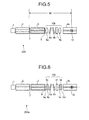
- Fig. 5 is a schematic cross section of a light source 200 according to the fifth embodiment.
- the spatial coupling unit 10b of the light source 200 includes the polarization filter 11, and a polarization-maintaining optical fiber 4b serves as an output light path.
- the polarization-maintaining optical fiber 4b includes a core region, a cladding region, and a stress applying member as the polarization-maintaining optical fiber 4a does.
- a fiber Bragg grating 12 is formed in the core region.
- the fiber Bragg grating 12 has a structure in which grating surfaces each perpendicular to the longitudinal direction of the core region are arranged at a predetermined pitch, and reflects a light having a full width half maximum of 10 nm and a wavelength of 1100 nm that is a transmission wavelength with respect to the etalon filters 6a and 6b by the Bragg reflection with a reflectivity equal to or more than 4% and equal to or less than 70%.
- the fiber Bragg grating 12 can be formed by phase masking in a way that a desired area along the longitudinal direction of the core region is irradiated with ultraviolet laser light.
- the reflectivity of the fiber Bragg grating 12 should preferably be equal to or more than 40% and equal to or less than 70% when the wavelength of the etalon filter is equal to or longer than 1075 nm, as in the case of the dielectric multilayer filter 8 according to the first embodiment.
- the fiber Bragg grating 12 and the dielectric multilayer filter 7 of the light source 200 form a laser resonator k2.
- the fiber Bragg grating 12 reflects a light having a full width half maximum of 10 nm, thereby functioning also as a wavelength selecting element. Therefore, the light source 200 can output a linearly-polarized laser light.
- the light source 200 can and output a sharp laser light having a narrower full width half maximum.
- a fiber Bragg grating may cause an unnecessary reflection peak at a wavelength of a desired wavelength band due to a production condition. However, there is no risk that unstable laser oscillation is caused in the light source 200 because, even if such an unnecessary light is reflected, the etalon filters 6a and 6b block the unnecessary light.
- the light source according to the sixth embodiment has a similar configuration to that of the light source according to the fifth embodiment, and leads to similar effects to those of the third embodiment.
- the light source according to the sixth embodiment is different from that of the fifth embodiment in that, for example, a distributed refractive index lens serves as a lens unit as in the case of the light source according to the second embodiment.
- Fig. 6 is a schematic cross section of a light source 200a according to the sixth embodiment.
- the fiber Bragg grating 12 of the light source 200a which is formed in the polarization-maintaining optical fiber 4b, serves as an output-side light reflecting unit as in the case of the light source 200
- the spatial coupling unit 10a of the light source 200a includes the distributed refractive index lenses 5c and 5d as a lens unit as in the case of the light source 100a.
- the dielectric multilayer AR coatings 9a to 9d are formed on the facets, from each of which a light is input or output, of the distributed refractive index lenses 5c and 5d. Therefore, the light source 200a can output a linearly-polarized laser light and a sharp laser light having a narrower full width half maximum. In addition, the light source can be downsized and highly productive.
- the light source according to the seventh embodiment has a similar configuration to that of the light source according to the sixth embodiment, and leads to similar effects to those of the sixth embodiment.
- the light source according to the seventh is different from that of the sixth embodiment in that, for example, a Bragg grating formed in an amplified-light waveguide serves as an input-side light reflecting unit.
- Fig. 7 is a schematic cross section of a light source 200b according to the seventh embodiment.
- the fiber Bragg grating 12 of the light source 200b which is formed in the polarization-maintaining optical fiber 4b, functions as an output-side light reflecting unit
- a fiber Bragg grating 12a of the light source 200b which is formed in the double-clad optical fiber 3a, serves as an input-side light reflecting unit.
- the double-clad optical fiber 3a includes a core region 31a, an inner cladding layer 32a, and an outer cladding layer 33a that have characteristics similar to those of the double-clad optical fiber 3.
- the fiber Bragg grating 12a has characteristics similar to those of the fiber Bragg grating 12, and the fiber Bragg grating 12a can be formed as the fiber Bragg grating 12 is formed.
- the fiber Bragg grating 12a of the double-clad optical fiber 3a is formed on a side close to the multimode optical fiber 2.
- the fiber Bragg grating 12 and the fiber Bragg grating 12a of the light source 200b form a laser resonator and also function as a wave selecting element. Therefore, the light source 200b can output a linearly-polarized laser light and a sharp laser light having a narrower full width half maximum.
- the light source according to the eighth embodiment has a similar configuration to that of the light source according to the sixth embodiment, and leads to similar effects to those of the sixth embodiment.
- the light source according to the eighth embodiment is different from that of the sixth embodiment in that, for example, a pumping-light waveguide and an amplified-light waveguide are spliced with ferrules.
- the coupling portion is explained in detail below.
- Fig. 8 is an external view of the coupling portion where the multimode optical fiber 2 and the double-clad optical fiber 3 of the light source according to the eighth embodiment are spliced, and an enlarged schematic cross section of the coupling portion.
- an end portion 25 on the output side of the multimode optical fiber 2 and an end portion 36 on the input side of the double-clad optical fiber 3 are stored in ferrules 26 and 37 that are cylindrical, and that are made of zirconia ceramics, in the light source according to the eight embodiment.
- the multimode optical fiber 2 or the double clad optical fiber 3 is inserted into any one of through holes formed on the central axis in the ferrules 26 and 37.
- the positions of the facets of the multimode optical fiber 2 and the double-clad optical fiber 3 are adjusted such that each of the ends of the multimode optical fiber 2 and the double-clad optical fiber 3 and a corresponding one of the ends of the ferrules 26 and 37 are on the same plane, and are fixed with an adhesive. Thereafter, the ends of the ferrules 26 and 37 are spliced by inserting the ferrules 26 and 37 from both ends of a split sleeve 13 into the split sleeve 13 that has a through hole having the same diameter as that of the outer diameters of the ferrules 26 and 37, and that is formed of zirconia ceramics. In this manner, the multimode optical fiber 2 and the double-clad optical fiber 3 are connected.
- the dielectric multilayer filter 7 is formed after the ferrule 26 is fixed to the multimode optical fiber 2 in the case of the eighth embodiment, the dielectric multilayer filter 7 is formed also on a facet 27 of the ferrule 26 as shown in the enlarged schematic cross section of Fig. 8 .
- the reference numerals 27 and 38 respectively indicate facets of the ferrules 26 and 37.
- the optical axes of the multimode optical fiber 2 and the double-clad optical fiber 3 easily match and can be inhibited from deviating. This reduces the connection loss. Furthermore, even if the attachment and detachment at the coupling portion are repeated, high reproducibility to compensate the coupling loss can be realized.
- An SC connector or an LC connector can be provided to each of the end portion on the output side of the multimode optical fiber 2 and the end portion on the output side of the double-clad optical fiber 3 to connect the multimode optical fiber 2 and the double-clad optical fiber 3 with the connectors via an SC adaptor or an LC adaptor that has a built-in sleeve.
- the light source according to the ninth embodiment has a similar configuration to that of the light source according to the sixth embodiment, and leads to similar effects to those of the sixth embodiment.
- the light source according to a ninth embodiment is different from that of the sixth embodiment in that, for example, a light output facet of a multimode optical fiber has a convex surface and a dielectric multilayer filter serving as an input-side light reflecting unit is formed on the surface.
- the coupling portion is explained in detail below.
- Fig. 9 is an enlarged schematic cross section of a coupling portion where a multimode optical fiber and a double-clad optical fiber of a light source according to the ninth embodiment are spliced.
- an output facet 24a of the multimode optical fiber 2a of the light source according to the ninth embodiment which includes the core region 21a and the cladding region 22a, has a concave surface having a depth d at a center-portion, and the dielectric multilayer filter 7a serving as an input-side light reflecting unit is formed thereon. Therefore, the dielectric multilayer filter 7a can be prevented from being in contact with the input facet 34 of the double-clad optical fiber 3, and accordingly, the facet can be prevented from being damaged.
- Such a concave surface can be realized by polishing. If the depth d is equal to or more than 1 ⁇ m, the facets can be prevented from being in contact with, and it suffices that the depth d be equal to or smaller than 50 ⁇ m. At least one of the output facet of the multimode optical fiber and the input facet of the optical fiber of the double-clad optical fiber should preferably have a concave surface, because such a surface brings an effect of preventing damage on the facets.
- Yb ions are employed as an amplification medium.
- ions of other rare-earth elements such as erbium (Er) or a combination of Yb ions and Er ions can be employed as an amplification medium.
- Er ions are used as an amplification medium
- a semiconductor pumping laser is used that generates a pumping laser light having a wavelength of approximately between 980 nm and 1480 nm. In this case, the wavelength band of a spontaneous emission light is approximately between 1520 nm and 1610 nm.
- a semiconductor pumping laser is used that generates a pumping laser light having a wavelength of approximately between 900 nm and 1000 nm.
- the wavelength band of a spontaneous emission light is approximately between 1520 nm and 1610 nm as well.
- an etalon filter is used as a wavelength selecting element.
- a band path filter of a dielectric multilayer can be used that is formed by alternately depositing high-refractive dielectric films made of, for example, Ta 2 O 5 and low-refractive dielectric films made of, for example, SiO 2 on a glass substrate.
- the output facet of the double-clad optical fiber has an angle of 4 degrees to the plane perpendicular to the optical axis.
- At least one of the facets of the pumping-light waveguide, the amplified-light waveguide, and the output-light waveguide, on which no dielectric multilayer filter serving as an input-side light reflecting unit or an output-side light reflecting unit is formed has the above angle.
- an antireflection coating is formed on any one of the facets of the pumping-light waveguide, the amplified-light waveguide, and the output-light waveguide, on which no dielectric multilayer filter serving as an input-side light reflecting unit or an output-side light reflecting unit is formed.
- a spherical lens or a distributed refractive index lens is used as a lens unit.
- a plano-convex lens, a graded index optical fiber, or an aspherical lens, or a combination thereof can be used.
- the polarization-maintaining optical fiber is used as the output-light waveguide. If a polarization-maintaining optical fiber is used as the amplified-light waveguide similarly, output of a light in a more stable polarization state can be obtained.
- the dielectric multilayer filter serving as the input-side reflecting unit is formed on the output facet of the multimode optical fiber serving as the pumping-light output waveguide.
- the dielectric multilayer filter can be formed on the input facet of the double-clad optical fiber.
- the dielectric multilayer filter serving as the output-side light reflecting unit is formed on the input facet of the single-mode optical fiber serving as the output-light waveguide according to the above embodiments, the dielectric multilayer filter can be formed on the output facet.
- a dielectric multilayer that reflects a light having a wavelength of a pumping laser light with a reflectivity equal to or more than 4% and equal to or less than 20% can be formed on the output facet of the amplified-light waveguide.
- the dielectric multilayer can reflect back a part of the pumping laser light not having been used for excitation of the amplification medium to the amplified-light waveguide. This increases the efficiency of laser oscillation.
- the core diameter of the multimode optical fiber serving as the pumping-light waveguide should preferably be equal to or smaller than 400 ⁇ m.
- a bundle fiber is formed that includes multimode optical fibers whose ends on one side are bundled, and that has a core diameter of 100 ⁇ m and a clad outer diameter of 125 ⁇ m, and the ends of the multimode optical fibers on the other side are attached to a plurality of semiconductor lasers.
- the double clad optical fiber is excited by the semiconductor lasers.
- that five or seven multimode optical fibers should preferably be bundled in consideration of light coupling efficiency.
- the multimode optical fibers to be bundled are arranged most closely to each other, three of the multimode optical fibers are linearly arranged. If the core diameter of the multimode optical fiber serving as the pumping-light waveguide is 400 ⁇ m, the light output from the bundle fiber can be sufficiently joined. According to the above embodiments, the multimode optical fiber is used as the pumping-light waveguide. Alternatively, a single mode optical fiber can be alternatively used as the pumping-light waveguide.
- the light source of the present invention can be preferably used in combination with a harmonic generating element for, for example, a laser microscope, a fluorescence analyzer for biomedicine, a biological analyzer for biomedicine, and a precision measurement device.
- a harmonic generating element for, for example, a laser microscope, a fluorescence analyzer for biomedicine, a biological analyzer for biomedicine, and a precision measurement device.
Applications Claiming Priority (3)
| Application Number | Priority Date | Filing Date | Title |
|---|---|---|---|
| JP2005166364 | 2005-06-07 | ||
| JP2005289551 | 2005-10-03 | ||
| PCT/JP2006/311448 WO2006132285A1 (ja) | 2005-06-07 | 2006-06-07 | 光源 |
Publications (1)
| Publication Number | Publication Date |
|---|---|
| EP1898504A1 true EP1898504A1 (de) | 2008-03-12 |
Family
ID=37498484
Family Applications (1)
| Application Number | Title | Priority Date | Filing Date |
|---|---|---|---|
| EP06766474A Withdrawn EP1898504A1 (de) | 2005-06-07 | 2006-06-07 | Lichtquelle |
Country Status (4)
| Country | Link |
|---|---|
| US (1) | US7801186B2 (de) |
| EP (1) | EP1898504A1 (de) |
| JP (1) | JPWO2006132285A1 (de) |
| WO (1) | WO2006132285A1 (de) |
Cited By (1)
| Publication number | Priority date | Publication date | Assignee | Title |
|---|---|---|---|---|
| EP2003745A2 (de) * | 2006-03-31 | 2008-12-17 | The Furukawa Electric Co., Ltd. | Lichtquelle |
Families Citing this family (6)
| Publication number | Priority date | Publication date | Assignee | Title |
|---|---|---|---|---|
| JP2007234711A (ja) * | 2006-02-28 | 2007-09-13 | Totoku Electric Co Ltd | 光源 |
| JP2010177469A (ja) * | 2009-01-29 | 2010-08-12 | Furukawa Electric Co Ltd:The | 光ファイバレーザおよび光ファイバ増幅器 |
| JP2011124460A (ja) * | 2009-12-14 | 2011-06-23 | Fujikura Ltd | 光ファイバ出射回路及びファイバレーザ |
| JP2012079885A (ja) * | 2010-09-30 | 2012-04-19 | Panasonic Electric Works Sunx Co Ltd | レーザ光出射装置およびレーザ光の中心波長および波長帯域幅の変更方法 |
| CN103647208B (zh) * | 2013-11-28 | 2016-08-17 | 中国矿业大学 | 一种有效控制特定染料随机介质中双峰辐射波长的方法 |
| US9453974B2 (en) * | 2014-07-24 | 2016-09-27 | Verizon Patent And Licensing Inc. | Eccentric cut sleeve for optical fiber adapter |
Family Cites Families (32)
| Publication number | Priority date | Publication date | Assignee | Title |
|---|---|---|---|---|
| JP2577785B2 (ja) * | 1988-09-26 | 1997-02-05 | 日本電信電話株式会社 | モードロック光ファイバレーザ装置 |
| JPH0435985A (ja) * | 1990-06-01 | 1992-02-06 | Oji Paper Co Ltd | インクジェット用紙 |
| JPH04359485A (ja) * | 1991-06-05 | 1992-12-11 | Ando Electric Co Ltd | 波長可変光ファイバレーザ |
| JPH07311319A (ja) * | 1994-05-16 | 1995-11-28 | Toyo Commun Equip Co Ltd | 光コネクタ |
| JPH0826768A (ja) * | 1994-07-19 | 1996-01-30 | Hoya Corp | Ybレーザーガラス及び該ガラスを用いたレーザー装置 |
| DE69527830T2 (de) | 1994-11-14 | 2003-01-02 | Mitsui Chemicals Inc | Wellenlängenstabilisierter Lichtquelle |
| JPH08213686A (ja) * | 1994-11-14 | 1996-08-20 | Mitsui Petrochem Ind Ltd | 波長安定化光源 |
| JP3330487B2 (ja) * | 1996-03-21 | 2002-09-30 | 富士写真フイルム株式会社 | レーザー装置 |
| US5659644A (en) * | 1996-06-07 | 1997-08-19 | Lucent Technologies Inc. | Fiber light source with multimode fiber coupler |
| JP3909119B2 (ja) * | 1996-10-31 | 2007-04-25 | 憲一 植田 | レーザ装置 |
| JPH10190105A (ja) * | 1996-12-25 | 1998-07-21 | Fuji Photo Film Co Ltd | 半導体発光装置 |
| US7576909B2 (en) * | 1998-07-16 | 2009-08-18 | Imra America, Inc. | Multimode amplifier for amplifying single mode light |
| JP2000133863A (ja) * | 1998-10-28 | 2000-05-12 | Shimadzu Corp | 固体レーザ装置 |
| JP2000353838A (ja) * | 1999-06-11 | 2000-12-19 | Kdd Corp | 誘導放出光発生装置 |
| US6268954B1 (en) * | 1999-08-20 | 2001-07-31 | Jds Fitel Inc. | Method and system for controlling the slope of an output response |
| JP2001230476A (ja) * | 2000-02-14 | 2001-08-24 | Furukawa Electric Co Ltd:The | 光増幅器 |
| JP2001326404A (ja) * | 2000-05-16 | 2001-11-22 | Fujikura Ltd | 希土類添加光ファイバ |
| EP1293018B1 (de) * | 2000-06-20 | 2004-10-13 | Evotec OAI AG | Faser-laser |
| JP4629852B2 (ja) | 2000-11-02 | 2011-02-09 | 古河電気工業株式会社 | 半導体レーザモジュールとそれを用いた光増幅器 |
| JP2002141608A (ja) | 2000-11-02 | 2002-05-17 | Furukawa Electric Co Ltd:The | 半導体レーザモジュールとそれを用いたラマン増幅器 |
| JP2002270928A (ja) * | 2001-03-08 | 2002-09-20 | Mitsubishi Cable Ind Ltd | 光励起方法、光増幅装置及びファイバレーザ装置、並びに光ファイバ |
| US6751241B2 (en) * | 2001-09-27 | 2004-06-15 | Corning Incorporated | Multimode fiber laser gratings |
| JP2003142759A (ja) * | 2001-11-06 | 2003-05-16 | Toshiba Corp | ファイバレーザ装置およびそれを用いた映像表示装置 |
| JP2003283036A (ja) * | 2001-12-27 | 2003-10-03 | Furukawa Electric Co Ltd:The | 半導体レーザモジュールおよびこれを用いたラマン増幅器 |
| US6816514B2 (en) * | 2002-01-24 | 2004-11-09 | Np Photonics, Inc. | Rare-earth doped phosphate-glass single-mode fiber lasers |
| JP2003258732A (ja) * | 2002-03-06 | 2003-09-12 | Mitsubishi Cable Ind Ltd | レーザ光源及びそれを用いた給電装置、並びに、無線搬送波放出システム及び携帯電話基地局 |
| JP2003309309A (ja) * | 2002-04-17 | 2003-10-31 | Itaru Watanabe | 高密度・高出力レーザー装置 |
| JP4359485B2 (ja) | 2002-11-25 | 2009-11-04 | 株式会社ミツトヨ | 表面性状測定機のワーク座標系原点設定方法とそのプログラムおよび装置 |
| JP4142495B2 (ja) * | 2003-05-19 | 2008-09-03 | 三菱電線工業株式会社 | ダブルクラッドファイバを用いた光学装置 |
| JP2005012008A (ja) | 2003-06-19 | 2005-01-13 | Fujikura Ltd | 光ファイバレーザ |
| US7120340B2 (en) * | 2003-06-19 | 2006-10-10 | Corning Incorporated | Single polarization optical fiber laser and amplifier |
| JP2005079197A (ja) * | 2003-08-28 | 2005-03-24 | Fujikura Ltd | 希土類元素添加ファイバ、光ファイバレーザ |
-
2006
- 2006-06-07 WO PCT/JP2006/311448 patent/WO2006132285A1/ja active Application Filing
- 2006-06-07 EP EP06766474A patent/EP1898504A1/de not_active Withdrawn
- 2006-06-07 JP JP2007520145A patent/JPWO2006132285A1/ja active Pending
-
2007
- 2007-12-07 US US11/952,647 patent/US7801186B2/en not_active Expired - Fee Related
Non-Patent Citations (1)
| Title |
|---|
| See references of WO2006132285A1 * |
Cited By (2)
| Publication number | Priority date | Publication date | Assignee | Title |
|---|---|---|---|---|
| EP2003745A2 (de) * | 2006-03-31 | 2008-12-17 | The Furukawa Electric Co., Ltd. | Lichtquelle |
| EP2003745A4 (de) * | 2006-03-31 | 2011-04-20 | Furukawa Electric Co Ltd | Lichtquelle |
Also Published As
| Publication number | Publication date |
|---|---|
| US7801186B2 (en) | 2010-09-21 |
| JPWO2006132285A1 (ja) | 2009-01-08 |
| US20080123695A1 (en) | 2008-05-29 |
| WO2006132285A1 (ja) | 2006-12-14 |
Similar Documents
| Publication | Publication Date | Title |
|---|---|---|
| US7801186B2 (en) | Light source | |
| US6816652B1 (en) | Pump fiber bundle coupler for double-clad fiber devices | |
| EP3479443B1 (de) | Optischer resonator, verfahren zur herstellung des optischen resonators und anwendungen davon | |
| US6704479B2 (en) | Method for coupling light into cladding-pumped fiber sources using an embedded mirror | |
| EP0435217B1 (de) | Gepumpte Laser mit eingebetteter Bragg-Gitterstruktur | |
| US6882664B2 (en) | Laser with internally coupled pump source | |
| US11402585B2 (en) | Optical connection structure | |
| EP1562059B1 (de) | Optische Faser-Kopplungsvorrichtung und Verfahren zum Koppeln optischer Fasern | |
| CA2835327A1 (en) | Excitation unit for a fibre laser | |
| JP2012209510A (ja) | 光ファイバレーザ光源 | |
| US8781274B2 (en) | Optical amplifier and resonator | |
| US6400746B1 (en) | Pump laser with low grating reflectivity | |
| CA2416953C (en) | A device for coupling light into the fiber | |
| CN114911009A (zh) | 光纤滤波器 | |
| Urquhart | Fibre laser resonators | |
| JP2002236239A (ja) | 光ファイバ、光モジュール、光ファイバ装置 | |
| US20090067188A1 (en) | Light source | |
| WO2014168040A1 (ja) | 光結合構造 | |
| CN111045152A (zh) | 光纤耦合器 | |
| WO2011007693A1 (ja) | 融着接続構造およびその構造を有する光導波路素子、これを用いる光源装置、および接続方法 | |
| JP2009059953A (ja) | 光ファイバレーザ | |
| EP4365651A1 (de) | Verfahren zur herstellung eines etalons und faserbasiertes etalon | |
| JP2010177469A (ja) | 光ファイバレーザおよび光ファイバ増幅器 | |
| CN115097556A (zh) | 色散薄膜、光纤插芯、色散腔镜、谐振腔装置及激光器 | |
| WO2011083781A1 (ja) | 光スイッチ機構およびその製造方法 |
Legal Events
| Date | Code | Title | Description |
|---|---|---|---|
| PUAI | Public reference made under article 153(3) epc to a published international application that has entered the european phase |
Free format text: ORIGINAL CODE: 0009012 |
|
| 17P | Request for examination filed |
Effective date: 20071219 |
|
| AK | Designated contracting states |
Kind code of ref document: A1 Designated state(s): DE GB |
|
| DAX | Request for extension of the european patent (deleted) | ||
| RBV | Designated contracting states (corrected) |
Designated state(s): DE GB |
|
| DAX | Request for extension of the european patent (deleted) | ||
| STAA | Information on the status of an ep patent application or granted ep patent |
Free format text: STATUS: THE APPLICATION HAS BEEN WITHDRAWN |
|
| 18W | Application withdrawn |
Effective date: 20140603 |