EP1895034A2 - Métier à tisser de grande largeur - Google Patents
Métier à tisser de grande largeur Download PDFInfo
- Publication number
- EP1895034A2 EP1895034A2 EP07016725A EP07016725A EP1895034A2 EP 1895034 A2 EP1895034 A2 EP 1895034A2 EP 07016725 A EP07016725 A EP 07016725A EP 07016725 A EP07016725 A EP 07016725A EP 1895034 A2 EP1895034 A2 EP 1895034A2
- Authority
- EP
- European Patent Office
- Prior art keywords
- weaving machine
- shaft
- machine according
- drive device
- wide
- Prior art date
- Legal status (The legal status is an assumption and is not a legal conclusion. Google has not performed a legal analysis and makes no representation as to the accuracy of the status listed.)
- Granted
Links
- 238000009941 weaving Methods 0.000 claims description 62
- 235000014676 Phragmites communis Nutrition 0.000 description 1
- 238000005452 bending Methods 0.000 description 1
- 239000004744 fabric Substances 0.000 description 1
- 239000000463 material Substances 0.000 description 1
- 230000002787 reinforcement Effects 0.000 description 1
- 230000002441 reversible effect Effects 0.000 description 1
Images


Classifications
-
- D—TEXTILES; PAPER
- D03—WEAVING
- D03C—SHEDDING MECHANISMS; PATTERN CARDS OR CHAINS; PUNCHING OF CARDS; DESIGNING PATTERNS
- D03C13/00—Shedding mechanisms not otherwise provided for
-
- D—TEXTILES; PAPER
- D03—WEAVING
- D03C—SHEDDING MECHANISMS; PATTERN CARDS OR CHAINS; PUNCHING OF CARDS; DESIGNING PATTERNS
- D03C13/00—Shedding mechanisms not otherwise provided for
- D03C13/02—Shedding mechanisms not otherwise provided for with independent drive motors
- D03C13/025—Shedding mechanisms not otherwise provided for with independent drive motors with independent frame drives
-
- D—TEXTILES; PAPER
- D03—WEAVING
- D03C—SHEDDING MECHANISMS; PATTERN CARDS OR CHAINS; PUNCHING OF CARDS; DESIGNING PATTERNS
- D03C9/00—Healds; Heald frames
- D03C9/06—Heald frames
- D03C9/0683—Arrangements or means for the linking to the drive system
Definitions
- the invention relates to a width loom with a number of shaft frames, each of which is connected by means of a number of Schaftzughebel and shank connecting rods with a Schaftzugstange to whose drive a drive device is provided, the Schaftzughebel are housed with the associated shaft connecting rods in weaving machine sections.
- Such width looms for example, have a weaving width of 8 to 30 m.
- the shank pull rods are correspondingly long and combined with lateral rod extensions which connect the shank pull rods to the drive device laterally provided on the loom.
- the drive device may be provided on one side of the wide loom.
- Such training requires correspondingly long connecting rods ie lateral rod extensions in which unwanted bends are often unavoidable.
- looms are also known in which a driving device for the shaft frame is provided on each of the two sides facing away from the wide weaving machine.
- the connecting rods ie the lateral rod extensions between the drive devices and the shaft tie rods, are also very long, so that even with such a design undesired bending out of the connecting rods is often unavoidable.
- a weaving machine which has a drive device on one side, wherein the connecting rods are connected at their ends remote from the shaft frame each with an eccentric drive.
- the eccentric drives are spaced apart from each other in the width direction of the weaving machine and arranged in pairs opposite one another in order to reduce the length of the connecting rods to the Schaftzugstangen.
- the connecting rods in a wide loom with corresponding shaft frame dimensions of 8 to 30 m are very long, so that unwanted bends are hardly avoidable.
- a weaving machine with a driving device provided on one side of the width loom and spaced apart in the width direction and having opposite drive means each connected to a connecting rod is known in the art, for example JP 10130986 A known.
- the connecting rods also applies to this latter loom, the above for EP 1 260 620 A1 made statements accordingly.
- This known weaving machine has a number of shaft frames, each of which is connected by means of a number of Schaftzughebel and shaft connecting rods with a Schaftzugstange.
- a drive device is provided to drive the Schaftzugstangen.
- the Schaftzugstangen are connected to the drive device forming drive means, which are provided laterally adjacent to the shaft frame.
- the DE 101 11 017 A1 discloses a weaving machine in which the shaft frames may, for example, have a width of 3 m and more.
- the shaft frames are not connected by means of shaft pull lever and shaft connecting rods with an associated Schaftzugstange, but there are referred to as push-pull rods shaft connecting rods are not hinged to Schaftzughebein, but at a suitable point fixed in its direction of rotation oscillating reversible rotor of an electrically controllable motor.
- a wide weaving machine known, for example, may have a weaving width of 8 m to 30 m.
- the store drives are angled in this known wide weaving machine, so that they extend underneath the shaft frame.
- These loading drives are stored in intermediate levels, which serve as loom reinforcement of the weaving machine and subdivide the loom into sections.
- the section distances can be 1 to 3 meters.
- the invention has for its object to provide a width loom of the type mentioned above, are avoided in the bends of connecting rods, as described above.
- the wide weaving machine according to the invention advantageously dispenses with connecting rods connecting the drive rods to the drive devices or reduces the number of lateral drive devices with associated connecting rods corresponding to the number of drive devices arranged in the weaving machine sections, so that unwanted deflections of long connecting rods are avoided.
- the fact that at least a number of the drive means are housed in the weaving machine sections there is also the advantage that the footprint for the weaving machine is reduced accordingly, because it can be dispensed with lateral drive devices at all or their number of the number housed in the weaving machine sections drive means is substantially reduced accordingly.
- weaving machine sections can be housed in each case a number of drive means for a corresponding number of shaft frames. This depends on the dimensions of the weaving machine sections defined by the drives of the weaving machine loader.
- the respective drive device it is possible for the respective drive device to be connected to the associated shaft pull lever.
- the respective drive device is connected to the associated shaft tie rod.
- the eccentric device can be provided for adjusting the shaft stroke of the associated shaft frame adjustable.
- the respective drive means is connected to the associated shifter lever by means of an elastic or articulated train.
- the respective train may e.g. have a toothed belt.
- the respective drive device can be connected to the associated shaft pull rod via an elastic or articulated train by means of a driver.
- This train may also have a toothed belt.
- the respective drive device can have a controllable drive motor with a gear.
- This drive motor may be, for example, a servo-controlled motor or the like.
- the weaving machine according to the invention can have width dimensions of 8 m to 30 m. After at least a number of drive means of the drive device in the defined by the drives of the weaving machine load Weaving machine sections are shifted, the footprint is limited either to the width dimension of the shaft frame or according to the number of laterally remaining, residual drive means only slightly larger than this.
- a very significant advantage is that the reliability of operation of the weaving machine according to the invention is comparatively large, because bends or buckles of very long connecting rods between the shaft levers and the drive means of a lateral drive device are at least reduced or even excluded.
- FIG. 1 illustrates schematically in a cutaway front view of an embodiment of the wide loom 10 with a number of shaft frame 12, of which in Figure 1, only one shaft frame 12 is shown cut centrally. The remaining shaft frames are located in a plane parallel to the plane of the drawing of FIG. 1 and are covered by the shaft frame 12 shown in FIG. The same also applies to the Schaftzughebel 14, the shaft connecting rods 16 and the Schaftzugstangen 18th
- the respective shaft frame 12 is connected by means of a number of Schaftzughebel 14 and shaft connecting rods 16 with an associated Schaftzugstange 18.
- the shank pull rod 18 extends through weaving machine sections 20 of the loom 10, of which only four weaving machine sections 20 are illustrated in FIG. 1 as a result of the sectional illustration.
- the weaving machine sections 20 are defined by the drives 21 of a weaving machine loader (not shown) which are spaced apart from one another in the weft direction and by means of which the weft thread is respectively struck against the edge of the goods.
- FIG. 2 schematically illustrates a design of the loom 10 with a two-sided shank cable, wherein two shank pull rods 18 are illustrated, each with associated shank levers 14, shank connecting rods 16 and shank frame 12 drawn in a cutaway view.
- the reference numeral 20 also in the figures 2, some of the weaving machine sections 20th and the reference numeral 21, the drives of the not shown weaving machine load of the weaving machine 10 illustrates.
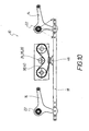
- FIG. 3 shows, in a perspective view, a section of a number of shank pull rods 18 with associated shank levers 14 of a loom 10 according to FIG. 2 with a corresponding number of shank frames 12 which are connected to the associated shank levers 14 by shaft connecting rods 16.
- the length of the shaft connecting rods 16 between the shaft frame 12 and the Schaftzughebeln 14 is adjustable.
- the shifter levers 14 are mounted on axles 22 in such a way that the shank pull levers 14 mounted on one axle 22 alternate with the shifter levers 14 mounted on the other axle 22. The same applies to the shaft connecting rods 16.
- FIGs 4 and 5 illustrate a defined by the drives 21 of the weaving loom loom section 20 of a weaving machine 10 according to the invention, wherein in the loom section 20, a drive means 24 is housed for an associated sectionally drawn shaft frame 12.
- the drive device 24 has a controllable drive motor 26 with a gear 28 and is connected to the associated shaft tension lever 14 by means of an eccentric device 30.
- the eccentric device 30 is adjustably connected to the associated Schaftzughebel 14. This adjustability is interpreted in Figure 4 by the arrows 32. By this adjustability 32 of the eccentric device 30, it is possible to adjust the shaft stroke of the associated shaft frame 12 as desired.
- FIGS 6 and 7 illustrate an embodiment of a weaving machine section 20 of a weaving machine 10 according to the invention, wherein in the by the Drives 21 of the weaving machine load defined weaving section 20 a drive means 24 is housed for a not shown in the figures 6 and 7, the shaft frame.
- the respective drive device 24 is connected directly to the associated shaft tension lever by means of an eccentric device 30.
- the eccentric device 30 is connected to the associated Schaftzugstange 18 by means of a bearing bracket 34 which has a width dimension, which is adapted to the width dimension of the associated Schaftzugstange 18.
- the drive device 24 may have a dimension in the width direction of the Schaftzugstange 18, which may be substantially larger than the width of the Schaftzugstangen 18 and the pitch width of the shank or the Schaftzuges.
- Reference number 14 designates one of the shank draw levers in FIGS. 6 and 7, which is connected to the associated shank drawbar 18 in a manner known per se.
- the reference numeral 22 designates the axle for a number of shaft pull levers 14, of which only one is visible in FIG.
- FIGS 8 and 9 show sections a Schaftzugstange 18 which is connected to a Schaftzughebel 14 which is mounted on an axle 22 and formed with a gear portion 36 of material ein Anlagenig.
- the gear portion 36 is concentric with the axis 22.
- the Schaftzughebel 14 is connected to a drive means 24 by means of an elastic train 38 which is formed by a toothed belt 40.
- the toothed belt 40 is fixed with its two ends 42 and 44 on the toothed belt section 36.
- FIG. 10 illustrates an embodiment in which the respective drive device 24 is connected to the associated shank pull rod 18 via an elastic pull 38 by means of a driver 46.
- the elastic train 38 is a toothed belt 40.
- FIGS. 1 to 10 The same details are designated in FIGS. 1 to 10 with the same reference numerals, so that it is not necessary to describe all the details in detail in conjunction with all figures.
Applications Claiming Priority (2)
| Application Number | Priority Date | Filing Date | Title |
|---|---|---|---|
| DE102006040474A DE102006040474A1 (de) | 2006-08-29 | 2006-08-29 | Antriebsvorrichtung für die Schaftrahmen einer Breitwebmaschine |
| DE200610040475 DE102006040475A1 (de) | 2006-08-29 | 2006-08-29 | Breitwebmaschine |
Publications (3)
| Publication Number | Publication Date |
|---|---|
| EP1895034A2 true EP1895034A2 (fr) | 2008-03-05 |
| EP1895034A3 EP1895034A3 (fr) | 2008-07-02 |
| EP1895034B1 EP1895034B1 (fr) | 2010-02-10 |
Family
ID=38769880
Family Applications (1)
| Application Number | Title | Priority Date | Filing Date |
|---|---|---|---|
| EP20070016725 Expired - Fee Related EP1895034B1 (fr) | 2006-08-29 | 2007-08-27 | Métier à tisser de grande largeur |
Country Status (2)
| Country | Link |
|---|---|
| EP (1) | EP1895034B1 (fr) |
| DE (1) | DE502007002798D1 (fr) |
Cited By (3)
| Publication number | Priority date | Publication date | Assignee | Title |
|---|---|---|---|---|
| DE102008032718B3 (de) * | 2008-07-11 | 2009-12-10 | Schneider & Ozga Ohg | Webmaschine |
| CN101922076B (zh) * | 2009-06-12 | 2012-08-15 | 赵斯伟 | 织机开口装置 |
| CN111101253A (zh) * | 2020-01-21 | 2020-05-05 | 江苏工程职业技术学院 | 一种间断式齿形带式织机开口机构 |
Citations (7)
| Publication number | Priority date | Publication date | Assignee | Title |
|---|---|---|---|---|
| DE19651799A1 (de) * | 1996-12-13 | 1998-06-18 | Schoenherr Webstuhlbau Gmbh | Antriebsvorrichtung für die Fachbildeelemente von Webmaschinen |
| US6092560A (en) * | 1997-07-30 | 2000-07-25 | Staeubli Gmbh | Shaft driving device for heald shafts |
| DE10059033A1 (de) * | 1999-12-09 | 2001-06-21 | Texo Ab Aelmhult | Web- oder Textilmaschine und Verfahren für eine derartige Maschine |
| EP1260620A1 (fr) * | 2001-05-21 | 2002-11-27 | Officina Meccanica Trinca Colonel Silvio & Figlio Sergio S.n.c. | Dispositif pour l'entraínement et le réglage automatique des cadres d'un métier à tisser |
| DE10331916A1 (de) * | 2003-07-15 | 2005-02-24 | Lindauer Dornier Gmbh | Antriebsvorrichtung zur Erzeugung einer hin- und hergehenden Bewegung eines angetriebenen Bauteil, insbesondere in Webmaschinen |
| EP1564320A2 (fr) * | 2004-02-10 | 2005-08-17 | Groz-Beckert KG | Dispositif de formation de la foule pour un métier à tisser |
| EP1571246A1 (fr) * | 2004-03-02 | 2005-09-07 | Promatech S.p.A. | Métier à tisser avec des cadres entraínés par moteur |
-
2007
- 2007-08-27 DE DE200750002798 patent/DE502007002798D1/de active Active
- 2007-08-27 EP EP20070016725 patent/EP1895034B1/fr not_active Expired - Fee Related
Patent Citations (7)
| Publication number | Priority date | Publication date | Assignee | Title |
|---|---|---|---|---|
| DE19651799A1 (de) * | 1996-12-13 | 1998-06-18 | Schoenherr Webstuhlbau Gmbh | Antriebsvorrichtung für die Fachbildeelemente von Webmaschinen |
| US6092560A (en) * | 1997-07-30 | 2000-07-25 | Staeubli Gmbh | Shaft driving device for heald shafts |
| DE10059033A1 (de) * | 1999-12-09 | 2001-06-21 | Texo Ab Aelmhult | Web- oder Textilmaschine und Verfahren für eine derartige Maschine |
| EP1260620A1 (fr) * | 2001-05-21 | 2002-11-27 | Officina Meccanica Trinca Colonel Silvio & Figlio Sergio S.n.c. | Dispositif pour l'entraínement et le réglage automatique des cadres d'un métier à tisser |
| DE10331916A1 (de) * | 2003-07-15 | 2005-02-24 | Lindauer Dornier Gmbh | Antriebsvorrichtung zur Erzeugung einer hin- und hergehenden Bewegung eines angetriebenen Bauteil, insbesondere in Webmaschinen |
| EP1564320A2 (fr) * | 2004-02-10 | 2005-08-17 | Groz-Beckert KG | Dispositif de formation de la foule pour un métier à tisser |
| EP1571246A1 (fr) * | 2004-03-02 | 2005-09-07 | Promatech S.p.A. | Métier à tisser avec des cadres entraínés par moteur |
Cited By (3)
| Publication number | Priority date | Publication date | Assignee | Title |
|---|---|---|---|---|
| DE102008032718B3 (de) * | 2008-07-11 | 2009-12-10 | Schneider & Ozga Ohg | Webmaschine |
| CN101922076B (zh) * | 2009-06-12 | 2012-08-15 | 赵斯伟 | 织机开口装置 |
| CN111101253A (zh) * | 2020-01-21 | 2020-05-05 | 江苏工程职业技术学院 | 一种间断式齿形带式织机开口机构 |
Also Published As
| Publication number | Publication date |
|---|---|
| EP1895034B1 (fr) | 2010-02-10 |
| DE502007002798D1 (de) | 2010-03-25 |
| EP1895034A3 (fr) | 2008-07-02 |
Similar Documents
| Publication | Publication Date | Title |
|---|---|---|
| EP2063007B1 (fr) | Dispositif de fabrication de tissus gaze | |
| EP0647283B1 (fr) | Mecanique d'armures pour une machine a tisser | |
| EP3052686A1 (fr) | Procédé et dispositif permettant d'appliquer des forces et d'imprimer des mouvements sur les fils de chaîne d'un métier à tisser | |
| EP1008683B1 (fr) | Procédé pour compenser le changement de la longueur et de la tension de la chaíne et métier à tisser pour la mise en oeuvre du procédé | |
| DE202009010788U1 (de) | Fördergutverteiler | |
| EP1895034B1 (fr) | Métier à tisser de grande largeur | |
| DE2631142B2 (de) | Maschine zur Steuerung der Webschäfte einer Webmaschine | |
| DE19711594A1 (de) | Vorrichtung zur Führung und Lagerung eines Greifertragorganes in Webmaschinen | |
| WO1999013145A1 (fr) | Dispositif de commande de fil | |
| DE202021102398U1 (de) | Kettenwirkmaschine | |
| DE102006040475A1 (de) | Breitwebmaschine | |
| WO1996006212A1 (fr) | Dispositif a lames | |
| DE102006040474A1 (de) | Antriebsvorrichtung für die Schaftrahmen einer Breitwebmaschine | |
| CH643014A5 (de) | Webverfahren und webmaschine zur durchfuehrung des webverfahrens. | |
| DE10326455B4 (de) | Falzmesserantrieb einer Falzmaschine | |
| DE202006013275U1 (de) | Breitwebmaschine | |
| EP2123813B1 (fr) | Dispositif d'entraînement d'un métier à tisser, ensemble de levier de renvoi et levier de renvoi pour celui-ci | |
| DE4111405C2 (fr) | ||
| DE1814269B2 (de) | Vorrichtung zur herstellung einer schnittleiste | |
| DE3700111A1 (de) | Zusatzgeraet fuer eine halbautomatische kettfaden-einzieheinrichtung fuer webmaschinen | |
| WO2008141657A1 (fr) | Dispositif de formation de la foule | |
| DE2223308A1 (de) | Tragwerk einer Einrichtung fuer den Ladenantrieb eines Webstuhles | |
| DE1953470A1 (de) | Einrichtung zum Verlagern der Grundkette bei Frottierwebstuehlen | |
| DE2509977A1 (de) | Schuetzenloser webstuhl | |
| WO2005012609A1 (fr) | Dispositif d'une machine a filer destine a former des aretes de gaze et machine a filer comportant un tel dispositif |
Legal Events
| Date | Code | Title | Description |
|---|---|---|---|
| PUAI | Public reference made under article 153(3) epc to a published international application that has entered the european phase |
Free format text: ORIGINAL CODE: 0009012 |
|
| AK | Designated contracting states |
Kind code of ref document: A2 Designated state(s): AT BE BG CH CY CZ DE DK EE ES FI FR GB GR HU IE IS IT LI LT LU LV MC MT NL PL PT RO SE SI SK TR |
|
| AX | Request for extension of the european patent |
Extension state: AL BA HR MK YU |
|
| PUAL | Search report despatched |
Free format text: ORIGINAL CODE: 0009013 |
|
| AK | Designated contracting states |
Kind code of ref document: A3 Designated state(s): AT BE BG CH CY CZ DE DK EE ES FI FR GB GR HU IE IS IT LI LT LU LV MC MT NL PL PT RO SE SI SK TR |
|
| AX | Request for extension of the european patent |
Extension state: AL BA HR MK RS |
|
| 17P | Request for examination filed |
Effective date: 20080829 |
|
| AKX | Designation fees paid |
Designated state(s): DE FR IT SE |
|
| GRAP | Despatch of communication of intention to grant a patent |
Free format text: ORIGINAL CODE: EPIDOSNIGR1 |
|
| GRAS | Grant fee paid |
Free format text: ORIGINAL CODE: EPIDOSNIGR3 |
|
| GRAA | (expected) grant |
Free format text: ORIGINAL CODE: 0009210 |
|
| AK | Designated contracting states |
Kind code of ref document: B1 Designated state(s): DE FR IT SE |
|
| REF | Corresponds to: |
Ref document number: 502007002798 Country of ref document: DE Date of ref document: 20100325 Kind code of ref document: P |
|
| PG25 | Lapsed in a contracting state [announced via postgrant information from national office to epo] |
Ref country code: SE Free format text: LAPSE BECAUSE OF FAILURE TO SUBMIT A TRANSLATION OF THE DESCRIPTION OR TO PAY THE FEE WITHIN THE PRESCRIBED TIME-LIMIT Effective date: 20100210 |
|
| PLBE | No opposition filed within time limit |
Free format text: ORIGINAL CODE: 0009261 |
|
| STAA | Information on the status of an ep patent application or granted ep patent |
Free format text: STATUS: NO OPPOSITION FILED WITHIN TIME LIMIT |
|
| 26N | No opposition filed |
Effective date: 20101111 |
|
| PG25 | Lapsed in a contracting state [announced via postgrant information from national office to epo] |
Ref country code: IT Free format text: LAPSE BECAUSE OF FAILURE TO SUBMIT A TRANSLATION OF THE DESCRIPTION OR TO PAY THE FEE WITHIN THE PRESCRIBED TIME-LIMIT Effective date: 20100210 |
|
| REG | Reference to a national code |
Ref country code: FR Ref legal event code: ST Effective date: 20110502 |
|
| PG25 | Lapsed in a contracting state [announced via postgrant information from national office to epo] |
Ref country code: FR Free format text: LAPSE BECAUSE OF NON-PAYMENT OF DUE FEES Effective date: 20100831 |
|
| PGFP | Annual fee paid to national office [announced via postgrant information from national office to epo] |
Ref country code: DE Payment date: 20150706 Year of fee payment: 9 |
|
| REG | Reference to a national code |
Ref country code: DE Ref legal event code: R119 Ref document number: 502007002798 Country of ref document: DE |
|
| PG25 | Lapsed in a contracting state [announced via postgrant information from national office to epo] |
Ref country code: DE Free format text: LAPSE BECAUSE OF NON-PAYMENT OF DUE FEES Effective date: 20170301 |