EP1894619A2 - Mikrokanalstruktur und Verfahren zur Feinteilchenherstellung damit - Google Patents
Mikrokanalstruktur und Verfahren zur Feinteilchenherstellung damit Download PDFInfo
- Publication number
- EP1894619A2 EP1894619A2 EP20070115399 EP07115399A EP1894619A2 EP 1894619 A2 EP1894619 A2 EP 1894619A2 EP 20070115399 EP20070115399 EP 20070115399 EP 07115399 A EP07115399 A EP 07115399A EP 1894619 A2 EP1894619 A2 EP 1894619A2
- Authority
- EP
- European Patent Office
- Prior art keywords
- channel
- dispersed
- phase
- phase introduction
- microchannel
- Prior art date
- Legal status (The legal status is an assumption and is not a legal conclusion. Google has not performed a legal analysis and makes no representation as to the accuracy of the status listed.)
- Granted
Links
- 239000010419 fine particle Substances 0.000 title claims abstract description 261
- 238000004519 manufacturing process Methods 0.000 title claims description 45
- 230000015572 biosynthetic process Effects 0.000 claims abstract description 131
- 239000012530 fluid Substances 0.000 claims abstract description 33
- 239000000758 substrate Substances 0.000 claims description 291
- 239000002245 particle Substances 0.000 claims description 105
- 238000005304 joining Methods 0.000 claims description 54
- 238000000034 method Methods 0.000 claims description 31
- 238000004891 communication Methods 0.000 claims description 19
- 239000012071 phase Substances 0.000 description 644
- 238000010586 diagram Methods 0.000 description 35
- YXFVVABEGXRONW-UHFFFAOYSA-N Toluene Chemical compound CC1=CC=CC=C1 YXFVVABEGXRONW-UHFFFAOYSA-N 0.000 description 33
- 239000004809 Teflon Substances 0.000 description 26
- 229920006362 Teflon® Polymers 0.000 description 26
- 238000012545 processing Methods 0.000 description 26
- 230000008569 process Effects 0.000 description 25
- 239000002002 slurry Substances 0.000 description 24
- 239000000243 solution Substances 0.000 description 18
- 239000000463 material Substances 0.000 description 15
- 239000004372 Polyvinyl alcohol Substances 0.000 description 13
- 229920002451 polyvinyl alcohol Polymers 0.000 description 13
- RZVAJINKPMORJF-UHFFFAOYSA-N Acetaminophen Chemical compound CC(=O)NC1=CC=C(O)C=C1 RZVAJINKPMORJF-UHFFFAOYSA-N 0.000 description 12
- 238000000206 photolithography Methods 0.000 description 12
- 239000005297 pyrex Substances 0.000 description 12
- 238000001039 wet etching Methods 0.000 description 12
- 239000007864 aqueous solution Substances 0.000 description 11
- 230000000052 comparative effect Effects 0.000 description 10
- 238000006243 chemical reaction Methods 0.000 description 8
- 238000002360 preparation method Methods 0.000 description 7
- 238000010030 laminating Methods 0.000 description 6
- 239000007787 solid Substances 0.000 description 6
- 229920005989 resin Polymers 0.000 description 5
- 239000011347 resin Substances 0.000 description 5
- 239000008346 aqueous phase Substances 0.000 description 4
- 239000002775 capsule Substances 0.000 description 4
- 239000003795 chemical substances by application Substances 0.000 description 4
- 239000011521 glass Substances 0.000 description 4
- 239000000853 adhesive Substances 0.000 description 3
- 230000001070 adhesive effect Effects 0.000 description 3
- 239000000919 ceramic Substances 0.000 description 3
- 230000008859 change Effects 0.000 description 3
- 230000000694 effects Effects 0.000 description 3
- 239000000499 gel Substances 0.000 description 3
- 230000010354 integration Effects 0.000 description 3
- 239000007788 liquid Substances 0.000 description 3
- 239000002184 metal Substances 0.000 description 3
- 229910052751 metal Inorganic materials 0.000 description 3
- 239000012074 organic phase Substances 0.000 description 3
- MYRTYDVEIRVNKP-UHFFFAOYSA-N 1,2-Divinylbenzene Chemical compound C=CC1=CC=CC=C1C=C MYRTYDVEIRVNKP-UHFFFAOYSA-N 0.000 description 2
- OKTJSMMVPCPJKN-UHFFFAOYSA-N Carbon Chemical compound [C] OKTJSMMVPCPJKN-UHFFFAOYSA-N 0.000 description 2
- 102000004190 Enzymes Human genes 0.000 description 2
- 108090000790 Enzymes Proteins 0.000 description 2
- PPBRXRYQALVLMV-UHFFFAOYSA-N Styrene Chemical compound C=CC1=CC=CC=C1 PPBRXRYQALVLMV-UHFFFAOYSA-N 0.000 description 2
- MCMNRKCIXSYSNV-UHFFFAOYSA-N Zirconium dioxide Chemical compound O=[Zr]=O MCMNRKCIXSYSNV-UHFFFAOYSA-N 0.000 description 2
- 239000003905 agrochemical Substances 0.000 description 2
- 239000003054 catalyst Substances 0.000 description 2
- -1 divinylbenzene Chemical compound 0.000 description 2
- 239000000839 emulsion Substances 0.000 description 2
- 239000000945 filler Substances 0.000 description 2
- 238000010438 heat treatment Methods 0.000 description 2
- 238000011031 large-scale manufacturing process Methods 0.000 description 2
- 239000011344 liquid material Substances 0.000 description 2
- 150000002739 metals Chemical class 0.000 description 2
- 239000003094 microcapsule Substances 0.000 description 2
- 239000000203 mixture Substances 0.000 description 2
- 230000000149 penetrating effect Effects 0.000 description 2
- 239000000843 powder Substances 0.000 description 2
- 239000010453 quartz Substances 0.000 description 2
- 238000010008 shearing Methods 0.000 description 2
- 239000010703 silicon Substances 0.000 description 2
- 229910052710 silicon Inorganic materials 0.000 description 2
- VYPSYNLAJGMNEJ-UHFFFAOYSA-N silicon dioxide Inorganic materials O=[Si]=O VYPSYNLAJGMNEJ-UHFFFAOYSA-N 0.000 description 2
- 239000002904 solvent Substances 0.000 description 2
- 239000000126 substance Substances 0.000 description 2
- 239000000725 suspension Substances 0.000 description 2
- 238000003786 synthesis reaction Methods 0.000 description 2
- DKPFZGUDAPQIHT-UHFFFAOYSA-N Butyl acetate Natural products CCCCOC(C)=O DKPFZGUDAPQIHT-UHFFFAOYSA-N 0.000 description 1
- 238000007792 addition Methods 0.000 description 1
- 235000021405 artificial diet Nutrition 0.000 description 1
- 239000011324 bead Substances 0.000 description 1
- 238000012824 chemical production Methods 0.000 description 1
- 239000007795 chemical reaction product Substances 0.000 description 1
- 238000007796 conventional method Methods 0.000 description 1
- 239000002537 cosmetic Substances 0.000 description 1
- 239000006071 cream Substances 0.000 description 1
- 239000003431 cross linking reagent Substances 0.000 description 1
- HNPSIPDUKPIQMN-UHFFFAOYSA-N dioxosilane;oxo(oxoalumanyloxy)alumane Chemical compound O=[Si]=O.O=[Al]O[Al]=O HNPSIPDUKPIQMN-UHFFFAOYSA-N 0.000 description 1
- 239000002270 dispersing agent Substances 0.000 description 1
- 239000003814 drug Substances 0.000 description 1
- 229940079593 drug Drugs 0.000 description 1
- 238000012377 drug delivery Methods 0.000 description 1
- 239000000975 dye Substances 0.000 description 1
- 238000005530 etching Methods 0.000 description 1
- 238000005194 fractionation Methods 0.000 description 1
- 239000007863 gel particle Substances 0.000 description 1
- FUZZWVXGSFPDMH-UHFFFAOYSA-N hexanoic acid Chemical compound CCCCCC(O)=O FUZZWVXGSFPDMH-UHFFFAOYSA-N 0.000 description 1
- 238000004128 high performance liquid chromatography Methods 0.000 description 1
- 238000002372 labelling Methods 0.000 description 1
- 238000003475 lamination Methods 0.000 description 1
- 239000004973 liquid crystal related substance Substances 0.000 description 1
- 238000000838 magnetophoresis Methods 0.000 description 1
- 239000002923 metal particle Substances 0.000 description 1
- 238000012986 modification Methods 0.000 description 1
- 230000004048 modification Effects 0.000 description 1
- 239000000178 monomer Substances 0.000 description 1
- 239000002304 perfume Substances 0.000 description 1
- 239000003505 polymerization initiator Substances 0.000 description 1
- 238000006116 polymerization reaction Methods 0.000 description 1
- 238000003672 processing method Methods 0.000 description 1
- 230000009467 reduction Effects 0.000 description 1
- 238000007789 sealing Methods 0.000 description 1
- 238000000926 separation method Methods 0.000 description 1
- 238000000638 solvent extraction Methods 0.000 description 1
- 125000006850 spacer group Chemical group 0.000 description 1
- 238000000992 sputter etching Methods 0.000 description 1
- 238000006467 substitution reaction Methods 0.000 description 1
- 229920001187 thermosetting polymer Polymers 0.000 description 1
- 238000012546 transfer Methods 0.000 description 1
- 239000011782 vitamin Substances 0.000 description 1
- 229940088594 vitamin Drugs 0.000 description 1
- 229930003231 vitamin Natural products 0.000 description 1
- 235000013343 vitamin Nutrition 0.000 description 1
- XLYOFNOQVPJJNP-UHFFFAOYSA-N water Substances O XLYOFNOQVPJJNP-UHFFFAOYSA-N 0.000 description 1
Images


Classifications
-
- B—PERFORMING OPERATIONS; TRANSPORTING
- B01—PHYSICAL OR CHEMICAL PROCESSES OR APPARATUS IN GENERAL
- B01J—CHEMICAL OR PHYSICAL PROCESSES, e.g. CATALYSIS OR COLLOID CHEMISTRY; THEIR RELEVANT APPARATUS
- B01J19/00—Chemical, physical or physico-chemical processes in general; Their relevant apparatus
- B01J19/0093—Microreactors, e.g. miniaturised or microfabricated reactors
-
- B—PERFORMING OPERATIONS; TRANSPORTING
- B01—PHYSICAL OR CHEMICAL PROCESSES OR APPARATUS IN GENERAL
- B01F—MIXING, e.g. DISSOLVING, EMULSIFYING OR DISPERSING
- B01F23/00—Mixing according to the phases to be mixed, e.g. dispersing or emulsifying
- B01F23/40—Mixing liquids with liquids; Emulsifying
- B01F23/41—Emulsifying
-
- B—PERFORMING OPERATIONS; TRANSPORTING
- B01—PHYSICAL OR CHEMICAL PROCESSES OR APPARATUS IN GENERAL
- B01J—CHEMICAL OR PHYSICAL PROCESSES, e.g. CATALYSIS OR COLLOID CHEMISTRY; THEIR RELEVANT APPARATUS
- B01J19/00—Chemical, physical or physico-chemical processes in general; Their relevant apparatus
-
- B—PERFORMING OPERATIONS; TRANSPORTING
- B01—PHYSICAL OR CHEMICAL PROCESSES OR APPARATUS IN GENERAL
- B01F—MIXING, e.g. DISSOLVING, EMULSIFYING OR DISPERSING
- B01F25/00—Flow mixers; Mixers for falling materials, e.g. solid particles
- B01F25/30—Injector mixers
- B01F25/31—Injector mixers in conduits or tubes through which the main component flows
- B01F25/314—Injector mixers in conduits or tubes through which the main component flows wherein additional components are introduced at the circumference of the conduit
- B01F25/3142—Injector mixers in conduits or tubes through which the main component flows wherein additional components are introduced at the circumference of the conduit the conduit having a plurality of openings in the axial direction or in the circumferential direction
- B01F25/31422—Injector mixers in conduits or tubes through which the main component flows wherein additional components are introduced at the circumference of the conduit the conduit having a plurality of openings in the axial direction or in the circumferential direction with a plurality of perforations in the axial direction only
-
- B—PERFORMING OPERATIONS; TRANSPORTING
- B01—PHYSICAL OR CHEMICAL PROCESSES OR APPARATUS IN GENERAL
- B01F—MIXING, e.g. DISSOLVING, EMULSIFYING OR DISPERSING
- B01F33/00—Other mixers; Mixing plants; Combinations of mixers
- B01F33/30—Micromixers
-
- B—PERFORMING OPERATIONS; TRANSPORTING
- B01—PHYSICAL OR CHEMICAL PROCESSES OR APPARATUS IN GENERAL
- B01F—MIXING, e.g. DISSOLVING, EMULSIFYING OR DISPERSING
- B01F33/00—Other mixers; Mixing plants; Combinations of mixers
- B01F33/80—Mixing plants; Combinations of mixers
- B01F33/81—Combinations of similar mixers, e.g. with rotary stirring devices in two or more receptacles
- B01F33/813—Combinations of similar mixers, e.g. with rotary stirring devices in two or more receptacles mixing simultaneously in two or more mixing receptacles
-
- B—PERFORMING OPERATIONS; TRANSPORTING
- B01—PHYSICAL OR CHEMICAL PROCESSES OR APPARATUS IN GENERAL
- B01J—CHEMICAL OR PHYSICAL PROCESSES, e.g. CATALYSIS OR COLLOID CHEMISTRY; THEIR RELEVANT APPARATUS
- B01J2/00—Processes or devices for granulating materials, e.g. fertilisers in general; Rendering particulate materials free flowing in general, e.g. making them hydrophobic
-
- B—PERFORMING OPERATIONS; TRANSPORTING
- B01—PHYSICAL OR CHEMICAL PROCESSES OR APPARATUS IN GENERAL
- B01F—MIXING, e.g. DISSOLVING, EMULSIFYING OR DISPERSING
- B01F33/00—Other mixers; Mixing plants; Combinations of mixers
- B01F33/80—Mixing plants; Combinations of mixers
- B01F33/81—Combinations of similar mixers, e.g. with rotary stirring devices in two or more receptacles
-
- B—PERFORMING OPERATIONS; TRANSPORTING
- B01—PHYSICAL OR CHEMICAL PROCESSES OR APPARATUS IN GENERAL
- B01J—CHEMICAL OR PHYSICAL PROCESSES, e.g. CATALYSIS OR COLLOID CHEMISTRY; THEIR RELEVANT APPARATUS
- B01J2219/00—Chemical, physical or physico-chemical processes in general; Their relevant apparatus
- B01J2219/00781—Aspects relating to microreactors
- B01J2219/00783—Laminate assemblies, i.e. the reactor comprising a stack of plates
-
- B—PERFORMING OPERATIONS; TRANSPORTING
- B01—PHYSICAL OR CHEMICAL PROCESSES OR APPARATUS IN GENERAL
- B01J—CHEMICAL OR PHYSICAL PROCESSES, e.g. CATALYSIS OR COLLOID CHEMISTRY; THEIR RELEVANT APPARATUS
- B01J2219/00—Chemical, physical or physico-chemical processes in general; Their relevant apparatus
- B01J2219/00781—Aspects relating to microreactors
- B01J2219/00819—Materials of construction
- B01J2219/00822—Metal
-
- B—PERFORMING OPERATIONS; TRANSPORTING
- B01—PHYSICAL OR CHEMICAL PROCESSES OR APPARATUS IN GENERAL
- B01J—CHEMICAL OR PHYSICAL PROCESSES, e.g. CATALYSIS OR COLLOID CHEMISTRY; THEIR RELEVANT APPARATUS
- B01J2219/00—Chemical, physical or physico-chemical processes in general; Their relevant apparatus
- B01J2219/00781—Aspects relating to microreactors
- B01J2219/00819—Materials of construction
- B01J2219/00824—Ceramic
- B01J2219/00826—Quartz
-
- B—PERFORMING OPERATIONS; TRANSPORTING
- B01—PHYSICAL OR CHEMICAL PROCESSES OR APPARATUS IN GENERAL
- B01J—CHEMICAL OR PHYSICAL PROCESSES, e.g. CATALYSIS OR COLLOID CHEMISTRY; THEIR RELEVANT APPARATUS
- B01J2219/00—Chemical, physical or physico-chemical processes in general; Their relevant apparatus
- B01J2219/00781—Aspects relating to microreactors
- B01J2219/00819—Materials of construction
- B01J2219/00824—Ceramic
- B01J2219/00828—Silicon wafers or plates
-
- B—PERFORMING OPERATIONS; TRANSPORTING
- B01—PHYSICAL OR CHEMICAL PROCESSES OR APPARATUS IN GENERAL
- B01J—CHEMICAL OR PHYSICAL PROCESSES, e.g. CATALYSIS OR COLLOID CHEMISTRY; THEIR RELEVANT APPARATUS
- B01J2219/00—Chemical, physical or physico-chemical processes in general; Their relevant apparatus
- B01J2219/00781—Aspects relating to microreactors
- B01J2219/00819—Materials of construction
- B01J2219/00831—Glass
-
- B—PERFORMING OPERATIONS; TRANSPORTING
- B01—PHYSICAL OR CHEMICAL PROCESSES OR APPARATUS IN GENERAL
- B01J—CHEMICAL OR PHYSICAL PROCESSES, e.g. CATALYSIS OR COLLOID CHEMISTRY; THEIR RELEVANT APPARATUS
- B01J2219/00—Chemical, physical or physico-chemical processes in general; Their relevant apparatus
- B01J2219/00781—Aspects relating to microreactors
- B01J2219/00819—Materials of construction
- B01J2219/00833—Plastic
-
- B—PERFORMING OPERATIONS; TRANSPORTING
- B01—PHYSICAL OR CHEMICAL PROCESSES OR APPARATUS IN GENERAL
- B01J—CHEMICAL OR PHYSICAL PROCESSES, e.g. CATALYSIS OR COLLOID CHEMISTRY; THEIR RELEVANT APPARATUS
- B01J2219/00—Chemical, physical or physico-chemical processes in general; Their relevant apparatus
- B01J2219/00781—Aspects relating to microreactors
- B01J2219/00851—Additional features
- B01J2219/00858—Aspects relating to the size of the reactor
- B01J2219/0086—Dimensions of the flow channels
-
- B—PERFORMING OPERATIONS; TRANSPORTING
- B01—PHYSICAL OR CHEMICAL PROCESSES OR APPARATUS IN GENERAL
- B01J—CHEMICAL OR PHYSICAL PROCESSES, e.g. CATALYSIS OR COLLOID CHEMISTRY; THEIR RELEVANT APPARATUS
- B01J2219/00—Chemical, physical or physico-chemical processes in general; Their relevant apparatus
- B01J2219/00781—Aspects relating to microreactors
- B01J2219/00889—Mixing
-
- B—PERFORMING OPERATIONS; TRANSPORTING
- B01—PHYSICAL OR CHEMICAL PROCESSES OR APPARATUS IN GENERAL
- B01J—CHEMICAL OR PHYSICAL PROCESSES, e.g. CATALYSIS OR COLLOID CHEMISTRY; THEIR RELEVANT APPARATUS
- B01J2219/00—Chemical, physical or physico-chemical processes in general; Their relevant apparatus
- B01J2219/00781—Aspects relating to microreactors
- B01J2219/00891—Feeding or evacuation
- B01J2219/00903—Segmented flow
-
- Y—GENERAL TAGGING OF NEW TECHNOLOGICAL DEVELOPMENTS; GENERAL TAGGING OF CROSS-SECTIONAL TECHNOLOGIES SPANNING OVER SEVERAL SECTIONS OF THE IPC; TECHNICAL SUBJECTS COVERED BY FORMER USPC CROSS-REFERENCE ART COLLECTIONS [XRACs] AND DIGESTS
- Y10—TECHNICAL SUBJECTS COVERED BY FORMER USPC
- Y10T—TECHNICAL SUBJECTS COVERED BY FORMER US CLASSIFICATION
- Y10T137/00—Fluid handling
- Y10T137/0318—Processes
- Y10T137/0396—Involving pressure control
Definitions
- the present invention relates to a method in which fine particles used in column fillers for fractionation/separation; microcapsules used in drugs, enzyme-containing capsules, cosmetics, perfumes, labeling/recording materials, adhesives, agricultural chemicals, or the like; and fine particles used in chemical reactions, solvent extractions, or the like; are stably produced in uniform sizes in a large amount,
- the present invention relates to a microchannel structure, microchannel structural body, and microchannel-structure laminated body for producing the above fine particles.
- microchannel structure which includes a microchannel having a length of about a few centimeters and a width and depth in the range of submicrometers to a few hundreds of micrometers on a glass substrate of a few centimeters square, to carry out chemical reactions or productions of fine particles by introducing fluids to the microchannel has attracted attention. It has been suggested that efficient chemical reactions can be carried out using such microchannel structures due to the effects of a short intermolecular distance and a large specific interfacial area in the microspace therein (for example, refer to non-patent document 1).
- fine particles with an extremely uniform particle diameter by introducing two kinds of liquids having different interfacial tensions to a channel which has a joining section (for example, refer to non-patent document 2 and patent documents 1 and 2).
- fine particles also includes fine particles, in which only the microdroplets or the surface of microdroplets are hardened (hereinafter referred to as "semi-hardened"), and the semi-solid fine particles having considerably high viscosity, other than the solid fine particles.
- the microchannel structure has a continuous-phase introduction inlet (2), a continuous-phase introduction channel (3), a dispersed-phase introduction inlet (4), a dispersed-phase introduction channel (5), a discharge channel (7), and a discharge outlet (8) on a microchannel substrate (1) and there is a joining section (6) where the introduced continuous-phase and dispersed-phase join hereinafter referred to as the "joining section").
- this method has the following problems. That is, in this method, the flow volumes of dispersed phase and continuous phase are controlled by changing the respective supply rate thereof in order to control the size of the fine particles, and thus slight changes in the supply rates of dispersed phase and continuous phase lead to changes in particle size. This results in difficulties in controlling particle diameter stably and also in obtaining fine particles with uniform particle diameters.
- microspace such as the capability for carrying out efficient chemical reactions due to the aforementioned effects of short intermolecular distance and large specific interfacial area in the microspace and the capability for producing fine particles with extremely uniform particle diameters by introducing two kinds of liquids having different interfacial tensions to a channel which has a joining section.
- the amount of fine-particle production per unit time is inevitably small in a single microchannel structure.
- non-patent documents 3 and 4 when it is possible to arrange numerous microchannel structures in parallel, the amount of fine-particle production per unit time can be increased while exploiting the aforementioned characteristics of microchannel structures (for example, refer to non-patent documents 3 and 4).
- non-patent document 3 attempts have been made to laminate the microchannel substrates having one microchannel by connecting them via a longitudinal hole which penetrates the common parts such as an inlet of reaction solutions and outlet of reaction products. It is said that chemical reactions and fine-particle production on an industrial scale while exploiting such characteristics of the microspace is possible by increasing the degree of integration of microchannel structures which are the minimum unit 2-dimensionally or by laminating the microchannel structures 3-dimensionally.
- the present invention is proposed in view of such conventional circumstances and its object is to provide a microchannel structure, microchannel structural body, microchannel-structure laminated body, and fine-particle production method which are for realizing the stable production of fine particles having uniform sizes and the production of fine particles in a large amount.
- the microchannel structure of the present invention is a microchannel structure having a dispersed-phase introduction channel which communicates with a dispersed-phase introduction inlet, continuous-phase introduction channel which communicates with a continuous-phase introduction inlet, discharge channel which communicates with a discharge outlet, fine-particle formation channel, and a plurality of branch channels for dispersed-phase introduction which are microchannels, and characterized in that one end of the fine-particle formation channel in the fluid traveling direction communicates with the continuous-phase introduction channel whereas the other end thereof communicates with the discharge channel, and that the side part of the dispersed-phase introduction channel and side part of the fine-particle formation channel communicate via the branch channels for dispersed-phase introduction to constitute one unit.
- microchannel structure of the present invention is the above microchannel structure characterized in that a branch channel for dispersed-phase introduction and the aforementioned fine-particle formation channel join at an arbitrary angle.
- microchannel structure of the present invention is the above microchannel structure characterized in that the cross sectional area of the branch channel for dispersed-phase introduction is smaller than the cross sectional area of the fine-particle formation channel.
- microchannel structure of the present invention is the above microchannel structure characterized in that the cross sectional area of the fine-particle formation channel gradually increases or remains the same from the communication position thereof with the continuous-phase introduction channel to the communication position thereof with the discharge channel.
- microchannel structure of the present invention is the above microchannel structure characterized in that the lengths of the branch channels for dispersed-phase introduction gradually increase or remain the same as the communication position of the branch channel for dispersed-phase introduction with the dispersed-phase introduction channel departs from the dispersed-phase introduction inlet.
- the microchannel structure of the present invention is the above microchannel structure in which n branch channels for dispersed-phase introduction (i.e. from Y 1 , which is the closest branch channel for dispersed-phase introduction to the dispersed-phase introduction inlet, to Y n , which is the furthest branch channel for dispersed-phase introduction from the dispersed-phase introduction inlet) communicate from the dispersed-phase introduction channel to the fine-particle formation channel and characterized by the following.
- the microchannel structural body of the present invention is a microchannel structural body characterized in that two or more of the above microchannel structures are formed on a substrate of the microchannel structural body and also the aforementioned two or more microchannel structures are arranged at an equal interval.
- microchannel structural body of the present invention is the above microchannel structural body characterized in that two or more of the above microchannel structures are formed on a substrate of the microchannel structural body.
- microchannel structural body of the present invention is the above microchannel structural body characterized in that two or more of the above microchannel structural bodies are arranged at an equal interval.
- microchannel structural body of the present invention is the above microchannel structural body characterized in that all the dispersed-phase introduction channel, continuous-phase introduction channel, fine-particle formation channel, discharge channel, and branch channels for dispersed-phase introduction are formed on one substrate.
- microchannel structural body of the present invention is the above microchannel structural body characterized in that the dispersed-phase introduction channel, continuous-phase introduction channel, fine-particle formation channel, discharge channel, and branch channel for dispersed-phase introduction are formed by being dispersed on two or more substrates.
- microchannel structure of the present invention is the above microchannel structure characterized in that all the dispersed-phase introduction channel, continuous-phase introduction channel, fine-particle formation channel, discharge Channel, and branch channel for dispersed-phase introduction have different widths and depths or have two or more different widths and depths.
- microchannel structural body of the present invention is the above microchannel structural body characterized in that all the dispersed-phase introduction channel, continuous-phase introduction channel, fine-particle formation channel, discharge channel, and branch channel for dispersed-phase introduction have different widths and depths or have two or more different widths and depths.
- microchannel structural body of the present invention is a microchannel-structure laminated body which is a microchannel-structure laminated body in which two or more of the above microchannel structural bodies are laminated and characterized in that a dispersed-phase introduction inlet, continuous-phase introduction inlet, and discharge outlet in said microchannel structural body penetrate the substrate of the microchannel structural body.
- microchannel structure of the present invention is the above microchannel structure characterized in that the width of the branch channel for dispersed-phase introduction or the width of the fine-particle formation channel is partially reduced at the joining section where the branch channel for dispersed-phase introduction and fine-particle formation channel join or in the vicinity thereof.
- microchannel structural body of the present invention is the above microchannel structural body characterized in that the width of the branch channel for dispersed-phase introduction or the width of the fine-particle formation channel is partially reduced at the joining section where the branch channel for dispersed-phase introduction and fine-particle formation channel join or in the vicinity thereof.
- microchannel-structure laminated body of the present invention is the above microchannel-structure laminated body characterized in that the width of the branch channel for dispersed-phase introduction or the width of the fine-particle formation channel is partially reduced at the joining section where the branch channel for dispersed-phase introduction and fine-particle formation channel join or in the vicinity thereof.
- the fine-particle production method of the present invention is a method for producing fine particles using the abovementioned microchannel structure and characterized in that a dispersed phase and continuous phase are merged at a joining section of the branch channel for dispersed-phase introduction and fine-particle formation channel to produce fine particles from the dispersed phase.
- the fine-particle production method of the present invention is the above fine-particle production method characterized in that the particle diameters of the produced fine particles are controlled by changing the angle where the branch channel for dispersed-phase introduction and fine-particle formation channel join.
- microchannel structure microchannel structural body, and microchannel-structure laminated body of the present invention will be described in further detail below by using figures.
- Fig. 4 shows the most basic schematic diagram of a microchannel structure of the present invention.
- the microchannel structure of the present invention is a microchannel structure having a dispersed-phase introduction channel (5) which communicates with a dispersed-phase introduction inlet (4), continuous-phase introduction channel (3) which communicates with a continuous-phase introduction inlet (2), discharge channel (7) which communicates with a discharge outlet (8), fine-particle formation channel (9), and branch channels for dispersed-phase introduction (10) which are microchannels.
- one end of the fine-particle formation channel (9) in the fluid traveling direction communicates with the continuous-phase introduction channel (3) whereas the other end thereof communicates with the discharge channel (7), and the side part (in the substrate plane direction) of the dispersed-phase introduction channel (5) and side part (in the substrate plane direction) of the fine-particle formation channel (9) communicate via the branch channels for dispersed-phase introduction (10) and they are arranged on a substrate.
- microchannel used in the present invention refers to a channel having a width of submicrons to 1 mm, depth of about submicrons to 1 mm, and length of about a few millimeters to a few centimeters although the length is not particularly limited.
- channel used in the present invention refers, in many cases, to a channel having a width, depth, and length which are the same or larger than those of microchannels, although the term “channel” may include microchannels at times.
- the aforementioned dispersed-phase introduction channel, continuous-phase introduction channel, discharge channel, and fine-particle formation channel may be microchannels or channels. Additionally, the aforementioned branch channel for dispersed-phase introduction is preferably a microchannel.
- the microchannel structure of the present invention is a microchannel structure in which the cross sectional area of the branch channel for dispersed-phase introduction is smaller than that of the fine-particle formation channel
- the width and depth of the branch channel for dispersed-phase introduction are preferably about a few micrometers to a few tens of micrometers and the width and depth of the fine-particle formation channel are preferably about a few tens of micrometers to 1 mm.
- the widths and depths of the dispersed-phase introduction channel and continuous-phase introduction channel are not particularly limited, they are preferably about a few tens of micrometers to 1 mm as those of the fine-particle formation channel.
- the width and depth of the discharge channel are not particularly limited either, they are preferably about a few tens of micrometers to 1 mm as those of the fine-particle formation channel.
- the sizes and shapes of the dispersed-phase introduction inlet and continunus-phase introduction inlet are not particularly limited as long as they can introduce predetermined fluids to the dispersed-phase introduction channel and continuous-phase introduction channel, respectively. Examples thereof include an inlet having a circular shape with a diameter of about 1.5 mm.
- the size and shape of the discharge outlet is not particularly limited as long as it can discharge continuous phase and the continuous phase containing the produced fine particles. Examples thereof include an outlet having a circular shape with a diameter of about 1.5 mm as that of the dispersed-phase introduction inlet and continuous-phase introduction inlet.
- the term "fluids" used in the present invention refers to a dispersed phase, a continuous phase, and the continuous phase containing the produced fine particles.
- fine particles refers to the fine particles produced by the continuous phase shearing the dispersed phase in the microchannel.
- the size of the fine particles is not particularly limited, the present invention is suited for producing fine particles having the size of a few micrometers to a few hundreds of micrometers and is even more suited for producing fine particles having the size of 10 ⁇ m to 100 ⁇ m.
- the fine particles in the present invention also include, other than the solid fine particles, microdroplets, semi-hardened fine particles where only the surface of microdroplets are hardened, and the semi-solid fine particles having considerably high viscosity.
- the dispersed phase used in the present invention is a liquid material for constituting the fine particles produced by the microchannel structure of the present invention.
- examples thereof include a medium in which materials for gel production such as monomers for polymerization like styrene, crosslinking agents like divinylbenzene, and polymerization initiators are dissolved in an appropriate solvent.
- the object of the present invention is to produce fine particles efficiently and the dispersed phase is not particularly limited as long as it can be supplied via the channels in the microchannel structure for the sake of achieving the above object and, furthermore, the component of the dispersed phase is not particularly limited either as long as it can farm fine particles.
- the dispersed phase may be a slurry material where solid matter such as fine powders are mixed in the dispersed phase, a laminar flow in which the dispersed phase is formed from a plurality of fluids, or a mixed fluid or a suspension (emulsion) formed from a plurality of fluids.
- the continuous phase used in the present invention is a liquid material used for producing fine particles from the dispersed phase by the microchannel structure of the present invention.
- examples thereof include a medium in which a dispersing agent for producing polyvinyl alcohol gels is dissolved in an appropriate solvent.
- the continuous phase is not particularly limited as long as it can be supplied via the channels in the microchannel structure and, furthermore, the component thereof is not particularly limited either as long as it can form fine particles.
- the continuous phase may be a slurry material where solid matters such as fine powders are mixed in the continuous phase, a laminar flow in which the continuous phase is formed from a plurality of fluids, or a mixed fluid or a suspension (emulsion) formed from a plurality of fluids.
- the outermost layer of the continuous phase will be an aqueous phase when the outermost layer of fine particles is an organic phase and the outermost layer of the continuous phase will be an organic phase when the outermost layer of fine particles is an aqueous phase.
- the dispersed phase and continuous phase preferably do not mix substantially or are incompatible.
- an organic phase such as butyl acetate which does not dissolve in water substantially will be used as the continuous phase, and vice versa when an aqueous phase is used as the continuous phase.
- Examples of the application of fine particles of the present invention include filling agents of columns for high performance liquid chromatography, zirconia beads for griding or catalyst supports and separating agents, catalysts such as zeolite particles, adhesives such as sealing/locking agents, insulating particles of metal particles, pressure measuring films, carbonless (pressure sensitive) copying papers, toner, thermal expansion agents, heating media, light control glass, gap agents (spacers), thermochromics (temperature sensitive liquid crystals and temperature sensitive dyes), capsules for magnetophoresis, agricultural chemicals, artificial diets, artificial seeds, air freshners, massage creams, lipsticks, capsules for vitamins, activated carbon, enzyme-containing capsules, and microcapsules and gels for DDS (drug delivery system) or the like.
- the microchannel structure of the present invention is preferably configured so that a plurality of branch channels for dispersed phase introduction and fine-particle formation channel join at an arbitrary angle.
- these pluralities of branch channels for dispersed phase introduction may be parallel to one another or not, the angles at which the branch channels for dispersed phase introduction and fine-particle formation channel join are preferably all equal.
- arbitrary angle refers to a "predetermined angle", which is determined at a stage where the microchannel structure is designed and which is based on the setting of a targeted particle diameter of fine particles and the amount of supply of the dispersed phase and continuous phase.
- the plurality of branch channels for dispersed phase introduction are all formed from the microchannels which are linear and are parallel to one another, it is preferably configured so that the branch channels for dispersed phase introduction and fine-particle formation channel join at an arbitrary angle.
- the microchannel structure of the present invention having 20 branch channels for dispersed phase introduction would have a capacity to produce 20 times as many fine particles per unit time as those produced by the microchannel structure having 1 branch channel for dispersed phase introduction. Needless to say, it is necessary to supply enough amount of the dispersed phase and continuous phase to meet the amount of fine particle production in this case.
- the fine-particle production method of the present invention produces fine particles by introducing the aforementioned dispersed phase and continuous phase to the microchannel structure of the present invention and by shearing the dispersed phase with the continuous phase at the joining section of the branch channel for dispersed-phase introduction and fine-particle formation channel. It is preferably configured so that the branch channel for dispersed-phase introduction and fine-particle formation channel join at an arbitrary angle. This is because it is possible to control the particle diameter of the produced fine particles by changing the angle of the joining section where the branch channel for dispersed-phase introduction joins the fine-particle formation channel.
- Fig. 21 shows relationships between the flow rate of continuous phase and particle diameter of the produced fine particles when the angles between the branch channel for dispersed-phase introduction and fine-particle formation channel are 22° and 44° as examples.
- the horizontal axis shows the flow rate of continuous phase and the vertical axis shows particle diameter of the produced fine particles.
- the flow rate of continuous phase is low at 5 ⁇ l/min or less, particle diameter changes greatly.
- the flow rate of continuous phase is 7 ⁇ l/min or more, particle diameter does not change greatly even if the flow rate of continuous phase changes.
- Fig. 21 shows relationships between the flow rate of continuous phase and particle diameter of the produced fine particles when the angles between the branch channel for dispersed-phase introduction and fine-particle formation channel are 22° and 44° as examples.
- the horizontal axis shows the flow rate of continuous phase and the vertical axis shows particle diameter of the produced fine particles.
- the particle diameter is about 85 ⁇ m when the angle is 22° and the particle diameter is about 65 ⁇ m when the angle is 44°, and thus it is apparent that the particle diameters of fine particles can be changed by the angle between the branch channel for dispersed-phase introduction and fine-particle formation channel. Accordingly, by setting the flow rate of the continuous phase to a condition in which the particle diameter does not change greatly and by changing the angle between the branch channel for dispersed-phase introduction and fine-particle formation channel, it is possible to control the particle diameter of the produced fine particles.
- the above process makes it easier to control the particle diameter of fine particles and is suited for the industrial, large scale production of fine particles.
- the setting of the angle of the joining section it may appropriately be determined depending on the targeted particle diameter of fine particles.
- the branch channel for dispersed-phase introduction it is not particularly limited as long as it communicates with the fine-particle formation channel at a position which is different from those of the continuous-phase introduction inlet and discharge outlet.
- Fig. 4 shows this point more specifically; i.e. in the microchannel structure in which n branch channels for dispersed-phase introduction (i.e.
- Y 1 which is the closest branch channel for dispersed-phase introduction to the dispersed-phase introduction inlet
- Y n which is the furthest branch channel for dispersed-phase introduction from the dispersed-phase introduction inlet
- the lengths from a 2 to a n are all equal.
- Figs. 6 to 18 show schematic diagrams of several embodiments of the present invention. Note that the present invention is not limited to these embodiments and not to mention that they can be changed arbitrarily so as not to fall beyond the scope of the present invention.
- Fig. 6 is an example where the cross sectional area of the fine-particle formation channel (9) gradually increases from the communication position thereof with the continuous-phase introduction channel (3) to the communication position thereof with the discharge channel (7), and also where the lengths of a plurality of branch channels for dispersed-phase introduction (10) gradually increase as the communication position of the branch channel for dispersed-phase introduction with the dispersed-phase introduction channel departs from the dispersed-phase introduction inlet.
- the cross sectional area of the fine-particle formation channel (9) near the continuous-phase introduction channel is about 5000 to 10000 ⁇ m 2 and the cross sectional area of the fine-particle formation channel near the discharge channel is about 9000 to 20000 ⁇ m 2 .
- the length of the branch channel for dispersed-phase introduction (10), which is at a position closest to the dispersed-phase introduction inlet, is about 3 to 4 mm and the length of the branch channel for dispersed-phase introduction, which is at a position furthest from the dispersed-phase introduction inlet, is about 3 to 6 mm.
- the pressure loss gradually increases in the fine-particle formation channel from the communication position with the continuous-phase introduction channel to the communication position with the discharge channel, and thus, it is easier for the continuous phase to flow back to the branch channel for dispersed-phase introduction as it gets closer the communication position with the continuous-phase introduction channel.
- the pressure loss is small and thus dispersed-phase will be easier to flow as the communication position between the branch channel for dispersed-phase introduction and dispersed-phase introduction channel departs further from the dispersed-phase introduction inlet.
- Fig. 6 it is configured so that the cross sectional area of the fine-particle formation channel gradually increases from the communication position thereof with the continuous-phase introduction channel to the communication position thereof with the discharge channel, and also that the lengths of a plurality of branch channels for dispersed-phase introduction gradually increase as the communication position of the branch channel for dispersed-phase introduction with the dispexsed-phase introduction channel departs from the dispersed-phase introduction inlet.
- the pressure loss at each branch channel for dispersed-phase introduction is equal and the pressure loss at each joining section with the branch channel for dispersed-phase introduction in the fine-particle formation channel is also equal, and thus it is possible to distribute the continuous phase uniformly to a plurality of branch channels for dispersed-phase introduction. As a result, it is possible to produce fine particles having an extremely uniform particle diameter in all the microchannels with the same conditions.
- the microchannel structural body of the present invention may be a microchannel structural body where two or more microchannel structures, which are formed from the aforementioned dispersed-phase introduction channel, continuous-phase introduction channel, fine-particle formation channel, discharge channel, and branch channel for dispersed-phase introduction, are formed on a substrate, or may be a microchannel structural body in which plural sets of the dispersed-phase introduction channels constituting microchannels are arranged at an equal interval.
- the microchannel-substrate by arranging one unit of the microchannel structure, which is formed from the dispersed-phase introduction channel, continuous-phase introduction channel, fine-particle formation channel, discharge channel, and branch channel for dispersed-phase introduction, on the circular microchannel-substrate radially along the circumference thereof at an equal interval, it is possible to efficiently integrate numerous microchannels 2-dimensionally. By arranging one unit of the microchannel structure at an equal interval as such, the dispersed phase and continuous phase can be uniformly supplied to each microchannel.
- Fig. 7 shows one example in which a plurality of microchannel structures are integrated.
- the microstructure formed from the dispersed-phase introduction channel, continuous-phase introduction channel, fine-particle formation channel, discharge channel, and 40 branch channels for dispersed-phase introduction as one unit, 50 units of the microchannel structures are arranged radially on a 5-inch substrate. Since 2000 joining sections between the dispersed phase and continuous phase are made by this configuration, the simultaneous production of 2000 fine particles will be possible on one substrate.
- two dispersed-phase introduction channels (5) are made to communicate via one dispersed-phase introduction inlet (4) and two discharge channels (7) communicate with one discharge outlet (8) by every two microchannels adjacent to each other as shown in Fig. 8.
- the length of the dispersed-phase introduction channel (5) may be increased as shown in Fig. 9. In other words, by increasing the pressure loss in the dispersed-phase introduction channel, it will be possible to supply the dispersed phase more uniformly to 1 unit of the abovementioned microchannel structure which will result in a preferable embodiment.
- the length of the dispersed-phase introduction channel may be adjusted so that the pressure loss of the dispersed phase is equal to or somewhat higher than that of the continuous phase at the joining section between the branch channel for dispersed-phase introduction and droplet formation channel.
- the pressure loss in the dispertsed-phase introduction channel may be adjusted by changing, not only the length of the dispersed-phase introduction channel but also the depth thereof, or the length and/or depth of the branch channel for dispersed-phase introduction.
- a substrate of microchannel structural body used in the present invention refers to a substrate having a channel or a microchannel, and through holes which are equivalent to the dispersed-phase introduction inlet, continuous-phase introduction inlet, and discharge outlet.
- the microchannel structural body used in the present invention includes one in which a cover body which functions as a lid for channels and microchannels is integrated with the microchannel substrate and one in which two or more microchannel substrates are laminated to integrate and the cover body is mounted on the uppermost substrate where channels and microchannels are formed. Note that the cover body may also have through holes equivalent to the dispersed-phase introduction inlet, continuous-phase introduction inlet, and discharge outlet.
- the materials for the substrate, in which microchannels are formed, and for the cover body, in which the formation/processing of microchannels and through holes is possible and having excellent chemical resistance and appropriate rigidity are preferable.
- the materials may be glass, quartz, ceramics, silicon, metals, resins, or the like.
- the sizes and shapes of the microchannel substrate and cover body are not particularly limited, the thickness thereof is preferably a few millimeters or less.
- channels and microchannels formed on a microchannel substrate an appropriate processing method may be selected depending on the material of the microchannel substrate.
- channels and microchannels can be made by directly processing the substrate material such as glass, quartz, ceramics, silicon, metals, and resins, due to mechanical processing, laser processing, etching, or the like.
- the substrate material is ceramic or resin, it is also possible to make channels and microchannels by using a mold which has a channel shape and is made of metal or the like.
- the small holes arranged in the cover body communicate the microchannel with the outside of the microchannel structural body and when they are used as an introduction inlet for fluids or as a discharge outlet, the diameter thereof is preferably about a few millimeters.
- the processing of the small holes in the cover body can be done by various means such as chemical means, mechanical means, laser irradiation and ion etching.
- microchannel structural body of the present invention two or more microchannel substrates or a microchannel substrate and a cover body can be laminated to integrate by means of joining due to a heat treatment, adhesion using adhesives such as a photosetting resin and thermosetting resin, or the like.
- the cover body it is possible to introduce fluids from the outside of the microchannel structural body to the microchannel and then to discharge the fluids back to the outside of the microchannel structural body, and thus it is possible for fluids to pass through the microchannel stably even when the amount thereof is small.
- the supply of fluids may be done using a general solution sending pump and mechanical means such as micropumps and syringe pumps can be used.
- all of the dispersed-phase introduction channel, continuous-phase introduction channel, fine-particle formation channel, discharge channel, and branch channel for dispersed-phase introduction may be formed on one substrate as shown in Fig. 11 while having the abovementioned structure and performance.
- all channels and microchannels can be formed on one substrate, and thus the number of microchannel substrates constituting the microchannel structural body can be reduced. Accordingly, microchannel structural bodies can be made more inexpensively.
- the dispersed-phase introduction channel, continuous-phase introduction channel, fine-particle formation channel, discharge channel, and branch channel for dispersed-phase introduction may be formed dispersedly on two or more substrates.
- the dispersed-phase introduction channel, continuous-phase introduction channel, fine-particle formation channel, discharge channel, and branch channel for dispersed-phase introduction may be formed dispersedly on two or more substrates.
- the processing condition of each microchannel substrate remains the same, and thus the processing steps can be more simplified.
- the microchannel-structure laminated body of the present invention is a microchannel-structure laminated body where two or more of the abovementioned microchannel structural bodies are laminated and it can be configured so that the dispersed-phase introduction inlet, continuous-phase introduction inlet, and discharge outlet in the microchannel structural body are formed by penetrating the microchannel substrate of the microchannel structural body.
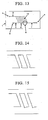
- Figs. 16 to 18 show examples where the aforementioned microchannel substrates (1) are laminated.
- the continuous-phase introduction inlet (2), dispersed-phase introduction inlet (4), and discharge outlet (8) are formed by penetrating their respective microchannel substrates. This embodiment is effective when laminating microchannel substrates and integrating numerous microchannels 3-dimensionally.
- channels can be integrated not only 2-dimentionally but also 3-dimeasionally and it is possible to produce fine particles in a larger amount.
- Figs 16 to 18 show examples where all the channels are formed on one microchannel substrate, it is also possible to laminate microchannel structural bodies where channels are formed on a plurality of microchannel substrates.
- the width of the branch channel for dispersed-phase introduction may be partially reduced as shown in Fig. 14, or the width of the fine-particle formation channel may be partially reduced as shown in Fig. 15.
- fine particles can stably be produced with uniform sizes and in a large amount.
- microchannel substrates are readily possible.
- the number of substrates required for the lamination of microchannel substrates is less.
- the reduction in pressure loss will be possible in the channels other than the fine-particle formation channel which has particularly small cross sectional area and is most appropriate for the fine-particle formation.
- the preparations of the microchannel structure, microchannel structural body, and microchannel-structure laminated body becomes easy.
- Fig. 4 shows a schematic diagram of the microchannel structure used in Example 1.
- the microchannel structure used in the present Example had a dispersed-phase introduction channel (5) which communicated with a dispersed-phase introduction inlet (4), continuous-phase introduction channel (3) which communicated with a continuous-phase introduction inlet (2), discharge channel (7) which communicated with a discharge outlet (8), and particle formation channel (9), and in which one end of the particle formation channel (9) communicated with the continuous-phase introduction channel whereas the other end thereof communicated with the discharge channel.
- the dispersed-phase introduction channel communicated the fine-particle formation channel via 40 branch channels for dispersed-phase introduction (10) which were arranged in parallel with the interval of 0.1 mm.
- the dispersed-phase introduction channel, continuous-phase introduction channel, discharge channel, particle formation channel, and branch channel for dispersed-phase introduction were formed as microchannels and their sizes (i.e. width/ depth/ length) were (95 ⁇ m/ 45 ⁇ m/ 9.45 mm), (333 ⁇ m/ 45 ⁇ m/ 11.8 mm), (275 ⁇ m/ 45 ⁇ m/ 11.2 mm), (195 ⁇ m/ 45 ⁇ m/ 3.92 mm), and (19 ⁇ m/ 7 ⁇ m/ 3.5 mm), respectively.
- they were formed so that the lengths of a 1 , b 1 , c 1 , and all the lengths of a 2 to a n in Fig. 4 were 9.45 mm, 11.8 mm, 11.2 mm, and 0.1 mm, respectively.
- the branch channel for dispersed-phase introduction and particle formation channel were formed so that they joined to form an angle of 70°.
- a microchannel substrate in which only the branch channel for dispersed-phase introduction was formed on one substrate
- microchannel substrate in which the dispersed-phase introduction channel, continuous-phase introduction channel, discharge channel, and particle formation channel were formed on one substrate
- a lid substrate (17) and bottom substrate (18) respectively were prepared as a lid substrate (17) and bottom substrate (18) respectively, and a microchannel structure was formed by joining the lid substrate and bottom substrate together.
- a piece of Pyrex (registered trademark; 70 mm ⁇ 30 mm ⁇ 1 mm) substrate was used for both the lid substrate and bottom substrate.
- the respective microchannels formed on the lid substrate and bottom substrate were formed by general photolithography and wet etching processes, and the lid substrate and bottom substrate were joined using a general heat seal process.
- small holes having a diameter of 0.6 mm were provided in advance on the lid substrate at positions which corresponded to the continuous-phase introduction inlet (2), dispersed-phase introduction inlet (4), and discharge outlet (8) using mechanical processing means. Note that the preparation method and substrate material of the present microchannel structure are not limited to the above.
- microsyringe pumps for supplying the continuous phase and dispersed phase via Teflon tubes were connected to the continuous-phase introduction inlet and dispersed-phase introduction inlet of the microchannel structure and the continuous phase and dispersed phase were supplied to the microchannel structure.
- a Teflon tube was also connected to the discharge outlet and the slurry containing the produced fine particles was discharged to recover. Note that toluene and 4% polyvinyl alcohol aqueous solution were used as the dispersed phase and continuous phase, respectively.
- the production rate of the slurry which was obtained by solution sending and which contained fine particles, was 20 ⁇ l/min.
- Example 1 where 40 branch channels for dispersed-phase introduction were integrated had the production rate of the slurry containing fine particles which was about 40 times higher. Accordingly, it was shown that by integrating the branch channels for dispersed-phase introduction, fine particles can be produced in a large amount which is proportional to the number of branch channels for dispersed-phase introduction.
- Fig. 6 shows a schematic diagram of the microchannel structure used in Example 2.
- the microchannel structure used in the present Example had a dispersed-phase introduction channel (5) which communicated with a dispersed-phase introduction inlet (4), continuous-phase introduction channel (3) which communicated with a continuous-phase introduction inlet (2), discharge channel (7) which communicated with a discharge outlet (8), and particle formation channel (9), and in which one end of the particle formation channel communicated with the continuous-phase introduction channel whereas the other end thereof communicated with the discharge channel.
- the dispersed-phase introduction channel communicated the particle formation channel via 40 branch channels for dispersed-phase introduction (10) which were arranged in parallel with the interval of 0.1 mm.
- the dispersed-phase introduction channel, continuous-phase introduction channel, and discharge channel were formed as microchannels and their sizes (i.e. width/ depth/ length) were (95 ⁇ m/ 45 ⁇ m/ 21.4 mm), (279 ⁇ m/ 45 ⁇ m/ 15.8 mm), and (250 ⁇ m/ 45 ⁇ m/ 9.9 mm).
- the particle formation channel was formed as microchannels with a depth and length of 45 ⁇ m and 3.92 mm respectively, and the width thereof was made so that it gradually increased from the communication position thereof with the continuous-phase introduction channel (153 ⁇ m) to the communication position thereof with the discharge channel (250 ⁇ m).
- the branch channel for dispersed-phase introduction was formed as microchannels with a width and depth of 19 ⁇ m and 7 ⁇ m respectively, and the length thereof was made so that it gradually increased from 3.5 mm to 5.18 mm as the communication position of the branch channel for dispersed-phase introduction and dispersed-phase introduction channel departs from the dispetsed-phase introduction inlet. Note that the branch channel for dispersed-phase introduction and particle formation channel were formed so that they joined to form an angle of 70°.
- a microchannel substrate in which only the branch channel for dispersed-phase introduction was formed on one substrate
- microchannel substrate in which the dispersed-phase introduction channel, continuous-phase introduction channel, discharge channel, and particle formation channel were formed on one substrate
- a lid substrate (17) and bottom substrate (18) respectively were prepared as a lid substrate (17) and bottom substrate (18) respectively, and a microchannel structural body was formed by joining the lid substrate and bottom substrate together.
- a piece of Pyrex (registered trademark; 70 mm ⁇ 30 mm ⁇ 1 mm) substrate was used for both the lid substrate and bottom substrate.
- the respective microchannels formed on the lid substrate and bottom substrate were formed by general photolithography and wet etching processes, and the lid substrate and bottom substrate were joined using a general heat seal process.
- small holes having a diameter of 0.6 mm were provided in advance on the lid substrate at positions which corresponded to the continuous-phase introduction inlet (2), dispersed-phase introduction inlet (4), and discharge outlet (8) using mechanical processing means. Note that the preparation method and substrate material of the present microchannel structure are not limited to the above.
- microsyringe pumps for supplying the continuous phase and dispersed phase via Teflon tubes were connected to the continuous-phase introduction inlet and dispersed-phase introduction inlet of the microchannel structure and the continuous phase and dispersed phase were supplied to the microchannel structure.
- a Teflon tube was also connected to the discharge outlet and the slurry containing the produced fine particles was discharged to recover through this Teflon tube. Note that toluene and 4% polyvinyl alcohol aqueous solution were used as the dispersed phase and continuous phase, respectively.
- the production of fine particles was observed at the merging section, in which the dispersed phase and continuous phase of the microchannel structure join, under the condition where both supply rates were stable.
- the average particle diameter of the fine particles was 32.2 ⁇ m and the CV value (%), which indicates the degree of variance of particle diameters, was 8.8% showing that the produced fine particles were extremely uniform.
- the production rate of the slurry which was obtained by solution sending and which contained particles, was 20 ⁇ l/min.
- Example 2 where 40 branch channels for dispersed-phase introduction were integrated had the production rate of the slurry containing fine particles which was about 40 times higher. Accordingly, it was shown that by integrating the branch channels for dispersed-phase introduction, fine particles can be produced in a large amount which is proportional to the number of branch channels for dispersed-phase introduction.
- the average particle diameter of the produced fine particles was 33.1 ⁇ m and the CV value (%), which indicates the degree of variance of particle diameters, was 9.9% showing that the produced fine particles were extremely uniform.
- the CV value (%) which indicates the degree of variance of particle diameters, was 9.9% showing that the produced fine particles were extremely uniform.
- Fig. 7 shows a schematic diagram of the microchannel substrate used in Example 3.
- the microchannel substrate shown in Fig. 7 was prepared as a microchannel substrate where the microchannel structures used in Example 2 were integrated on one circular substrate.
- 50 units of the microchannel structure, 1 unit of which was formed from the dispersed-phase introduction channel, continuous-phase introduction channel, fine-particle formation channel, discharge channel, and 40 branch channels for dispersed-phase introduction were arranged in circles on a Pyrex (registered trademark) substrate having a diameter and thickness of 5 inches and 1.2 mm respectively, with an equal interval.
- Pyrex registered trademark
- the continuous-phase introduction inlet (2), dispersed-phase introduction inlet (4), and discharge outlet (8) in the microchannel structure were arranged so that their positions were on concentric circles having a radius of 30 mm, 35 mm, and 55 mm, respectively. With such a configuration, it was possible to prepare a microchannel substrate having 2000 joining sections of the dispersed phase and continuous phase on one substrate and in which fine particles could be produced simultaneously at the aforementioned 2000 joining sections. Note that in order to reduce the number of the dispersed-phase introduction inlet and discharge outlet, 2 dispersed-phase introduction channels (5) and 2 discharge channels (7) were communicated by one dispersed-phase introduction inlet (4) and one discharge outlet respectively, at every two units of microchannel structures which were adjacent to each other as shown in Fig. 8.
- microchannel substrate having this microchannel structure was prepared by general photolithography and wet etching processes as in Example 1.
- the through holes of the continuous-phase introduction inlet, dispersed-phase introduction inlet, and discharge outlet in the microchannel structure were formed as the through holes having a diameter of 1 mm by mechanical processing.
- Fig. 23 shows a schematic diagram of the microchannel structural body used in Example 3.
- the microchannel structural body was prepared so that a channel substrate for supplying continuous phase (22) having a reservoir (19) and supplying channel (21) which supplied continuous phase was joined on the top face of the aforementioned microchannel substrate (1), and a channel substrate for supplying dispersed phase (23) having a reservoir (20) and supplying channel (21) which supplied dispersed phase was joined on the bottom face of the aforementioned microchannel substrate (1).
- Pyrex (registered trademark) substrate having a diameter and thickness of 5 inches and 1.2 mm respectively, was used to prepare the channel substrate for supplying continuous phase and channel substrate for supplying dispersed phase which were joined on the top and bottom faces of the microchannel substrate.
- the reservoirs and supply channels formed on the channel substrate for supplying continuous phase and channel substrate for supplying dispersed phase were formed by general photolithography and wet etching processes.
- the joining of the microchannel substrate with the channel substrate for supplying continuous phase and channel substrate for supplying dispersed phase was carried out by a general heat seal process.
- the through hole (24) of the reservoir of the channel substrate for supplying continuous phase, through hole (25) of the reservoir of the channel substrate for supplying dispersed phase, and through holes of fluid discharge outlet (26) were formed as the through holes having a diameter of 1 mm by mechanical processing.
- the shape of the reservoirs of the channel substrate for supplying continuous phase and channel substrate for supplying dispersed phase was a cylinder having a diameter and depth of 30 mm and 300 ⁇ m, respectively.
- linear supply channels were formed radially from the circumferences of the reservoirs.
- the supply channels from the reservoir of the structural body for supplying continuous phase had a length, width, and depth of 15 mm, 1 mm, and 300 ⁇ m respectively, and 50 of them were formed at an equal interval.
- the supply channels from the reservoir of the structural body for supplying dispersed phase had a length, width, and depth of 20 mm,1 mm, and 300 ⁇ m respectively, and 25 of them were formed at an equal interval.
- 25 of the through holes of fluid discharge outlet (26) on the channel substrate for supplying dispersed phase were arranged at positions on a concentric circle having a radius of 55 mm so as to correspond with the positions of discharge outlet (8) of the microchannel substrate (1).
- the continuous-phase introduction inlets and dispersed-phase introduction inlets in respective microchannel structures formed on microchannel substrates could communicate via the linear supply channels arranged radially from the reservoirs which were provided on the channel substrate for supplying continuous phase and channel substrate for supplying dispersed phase which were joined on the top and bottom faces of the microchannel substrate.
- solution sending pumps for supplying the continuous phase and dispersed phase via Teflon tubes were connected to the through hole (24) of the reservoir on the channel substrate for supplying continuous phase and to the through hole (25) of the reservoir on the channel substrate for supplying dispersed phase of the microchannel structural body, and the continuous phase and dispersed phase were supplied to the microchannel structural body Moreover, a Teflon tube was also connected to each of 25 fluid discharge outlets formed on the channel substrate for supplying dispersed phase and the slurry containing the produced fine particles was discharged to recover through this Teflon tube. Note that toluene and 4% polyvinyl alcohol aqueous solution were used as the dispersed phase and continuous phase, respectively.
- the production of fine particles was observed at the merging section, in which the dispersed phase and continuouse phase in the microchannel structural body join, under the condition where both supply rates were stable.
- the average particle diameter of the fine particles was 32.5 ⁇ m and the CV value (%), which indicates the degree of variance of particle diameters, was 11.7% showing that the produced fine particles were relatively uniform.
- the production rate of the slurry which was obtained by solution sending and which contained fine particles, was 1 ml/min.
- Example 3 which uses a microchannel structural body, in which 50 microchannel structures of Example 2 were integrated, had the production rate of the slurry containing fine particles which was about 50 times higher compared to that of Example 2, and thus it was shown that by integrating microchannel structures, fine particles can be produced in a large amount which is proportional to the number of microchannel structures.
- the average particle diameter of the produced fine particles was 33.2 ⁇ m and the CV value (%), which indicates the degree of variance of particle diameters, was 9.8% showing that the produced fine particles were extremely uniform.
- the fluctuation of the particle diameter down to an extremely low level of about 2% even when the supply rate of the continuous phase fluctuated by about 30% in the present Example 3, and fine particles could be produced stably with a particle diameter, which was more or less within an acceptable range of the target diameter (the acceptable range assumed in the present Example was between 27 to 37 ⁇ m), even when the supply rate of the continuous phase fluctuated greatly.
- a microchannel-structure laminated body was made by laminating 5 microchannel substrates used in Example 3, joining the channel substrate for supplying continuous phase used in Example 3 onto the top face of the uppermost microchannel substrate, and joining the channel substrate for supplying dispersed phase used in Example 3 onto the bottom face of the lowermost microchannel substrate. Joining of microchannel substrate with the channel substrate for supplying continuous phase and with the channel substrate for supplying dispersed phase was carried out using a general heat seal process. With such a configuration, it was possible to prepare a microchannel-structure laminated body having 10000 joining sections of the dispersed phase and continuous phase per one unit of the laminated body and in which fine particles could be produced simultaneously at the aforementioned 10000 joining sections.
- solution sending pumps for supplying the continuous phase and dispersed phase via Teflon tubes were connected to the through hole (24) of the reservoir on the channel substrate for supplying continuous phase and to the through hole (25) of the reservoir on the channel substrate for supplying dispersed phase of the microchannel-structure laminated body, and the continuous phase and dispersed phase were supplied to the microchannel-structure laminated body.
- a Teflon tube was also connected to each of 25 fluid discharge outlets formed on the channel substrate for supplying dispersed phase and the slurry containing the produced fine particles was discharged to recover through this Teflon tube. Note that toluene and 4% polyvinyl alcohol aqueous solution were used as the dispersed phase and continuous phase, respectively.
- the production of fine particles was observed at the merging section, in which the dispersed phase and continuous phase in the microchannel-structure laminated body join, under the condition where both supply rates were stable.
- the average particle diameter of the fine particles was 34.3 ⁇ m and the CV value (%), which indicates the degree of variance of particle diameters, was 10.8% showing that the produced fine particles were relatively uniform.
- the production rate of the slurry which was obtained by solution sending and which contained fine particles, was 5 ml/min.
- Example 4 which uses a microchannel-structure laminated body, in which 5 microchannel substrates of Example 3 were laminated, had the production rate of the slurry containing fine particles which was about 5 times higher compared to that of Example 3, and thus it was shown that by laminating microchannel substrates, fine particles could be produced in a large amount which was proportional to the number of microchannel substrates.
- the average particle diameter of the produced fine particles was 36.6 ⁇ m and the CV value (%), which indicates the degree of variance of particle diameters, was 9.4% showing that the produced fine particles were extremely uniform.
- the fluctuation of the particle diameter down to an extremely low level of about 6% even when the supply rate of the continuous phase fluctuated by about 30% in the present Example 4, and fine particles could be produced stably with a particle diameter, which was more or less within an acceptable range of the target diameter (the acceptable range assumed in the present Example was between 27 to 37 ⁇ m), even when the supply rate of the continuous phase fluctuated greatly.
- a microchannel-structure laminated body was made by laminating 20 microchannel substrates used in Example 3, joining the channel substrate for supplying continuous phase used in Example 3 onto the top face of the uppermost microchannel substrate, and joining the channel substrate for supplying dispersed phase used in Example 3 onto the bottom face of the lowermost microchannel substrate. Joining of microchannel substrate with the channel substrate for supplying continuous phase and with the channel substrate for supplying dispersed phase was carried out using a general heat seal process. With such a configuration, it was possible to prepare a microchannel-structure laminated body having 40000 joining sections of the dispersed phase and continuous phase substantially per one unit of the laminated body and in which fine particles could be produced simultaneously at the aforementioned 40000 joining sections.
- solution sending pumps for supplying the continuous phase and dispersed phase via Teflon tubes were connected to the through hole (24) of the reservoir on the channel substrate for supplying continuous phase and to the through hole (25) of the reservoir on the channel substrate for supplying dispersed phase of the microchannel-structure laminated body, and the continuous phase and dispersed phase were supplied to the microchannel-structure laminated body.
- a Teflon tube was also connected to each of 25 fluid discharge outlets formed on the channel substrate for supplying dispersed phase and the slurry containing the produced fine particles was discharged to recover through this Teflon tube. Note that toluene and 4% polyvinyl alcohol aqueous solution were used as the dispersed phase and continuous phase, respectively.
- the production of fine particles was observed at the merging section, in which the dispersed phase and continuous phase in the microchannel-structure laminated body join, under the condition where both supply rates were stable.
- the average particle diameter of the fine particles was 34.3 ⁇ m and the CV value (%), which indicates the degree of variance of particle diameters, was 10.4% showing that the produced fine particles were relatively uniform.
- the production rate of the slurry which was obtained by solution sending and which contained fine particles, was 20 ml/min.
- Example 5 which uses a microchannel-structure laminated body, in which 20 microchannel substrates of Example 3 were laminated, had the production rate of the slurry containing fine particles which was about 20 times higher compared to that of Example 3, and thus it was shown that by laminating microchannel substrates, fine particles could be produced in a large amount which was proportional to the number of microchannel substrates.
- the average particle diameter of the produced fine particles was 36.0 ⁇ m and the CV value (%), which indicates the degree of variance of particle diameters, was 9.8% showing that the produced fine particles were extremely uniform.
- Fig. 4 shows a schematic diagram of the microchannel structure used in Example 6.
- the microchannel structure used in the present Example had a dispersed-phase introduction channel (5) which communicated with a dispersed-phase introduction inlet (4), continuous-phase introduction channel (3) which communicated with a continuous-phase introduction inlet (2), discharge channel (7) which communicated with a discharge outlet (8), and particle formation channel (9), and in which one end of the particle formation channel (9) communicated with the continuous-phase introduction channel whereas the other end thereof communicated with the discharge channel.
- the dispersed phase introduction channel communicated the particle formation channel via 40 branch channels for dispersed-phase introduction (10) which were arranged in parallel with the interval of 0,1 mm.
- the dispersed-phase introduction channel, continuous-phase introduction channel, discharge channel, particle formation channel, and branch channel for dispersed-phase introduction were formed as microchannels and their sizes (i.e. width/ depth/ length) were (200 ⁇ m/ 140 ⁇ m/ 98 mm), (530 ⁇ m/ 140 ⁇ m/ 11.8 mm), (480 ⁇ m/ 140 ⁇ m/ 11.2 mm), (300 ⁇ m/ 140 ⁇ m/ 3.9 mm), and (41 ⁇ m/ 18 ⁇ m/ 3.5 mm), respectively.
- they were formed so that the lengths of a 1 , b 1 , c 1 , and all the lengths of a 2 to a n in Fig. 4 were 9.5 mm, 11.8 mm, 11.2 mm, and 0.1 mm, respectively.
- the branch channel for dispersed-phase introduction and particle formation channel were formed so that they joined to form an angle of 70°.
- a microchannel substrate in which only the branch channel for dispersed-phase introduction was formed on one substrate
- microchannel substrate in which the dispersed-phase introduction channel, continuous-phase introduction channel, discharge channel, and particle formation channel were formed on one substrate
- a lid substrate (17) and bottom substrate (18) respectively were prepared as a lid substrate (17) and bottom substrate (18) respectively, and a microchannel structure was formed by joining the lid substrate and bottom substrate together.
- a piece of Pyrex (registered trademark; 70 mm ⁇ 30 mm ⁇ 1 mm) substrate was used for both the lid substrate and bottom substrate.
- the respective microchannels formed on the lid substrate and bottom substrate were formed by general photolithography and wet etching processes, and the lid substrate and bottom substrate were joined using a general heat seal process.
- small holes having a diameter of 0.6 mm were provided in advance on the lid substrate at positions which corresponded to the continuous-phase introduction inlet (2), dispersed-phase introduction inlet (4), and discharge outlet (8) using mechanical processing means. Note that the preparation method and substrate material of the present microchannel structure are not limited to the above.
- the microchannel substrate where the abovementioned microchannel structures were integrated on one circular substrate was prepared.
- 50 units of the microchannel structure 1 unit of which was formed from the dispersed-phase introduction channel, continuous-phase introduction channel, fine-particle formation channel, discharge channel, and 40 branch channels for dispersed-phase introduction, were arranged in circles on a Pyrex (registered trademark) substrate having a diameter and thickness of 5 inches and 1.2 mm respectively, with an equal interval.
- the continuous-phase introduction inlet (2), dispersed-phase introduction inlet (4), and discharge outlet (8) in the microchannel structure were arranged so that their positions were on concentric circles having a radius of 30 mm, 35 mm, and 55 mm, respectively.
- microchannel substrate having 2000 joining sections of the dispersed phase and continuous phase on one substrate and in which fine particles could be produced simultaneously at the aforementioned 2000 joining sections.
- 2 dispersed-phase introduction channels (5) and 2 discharge channels (7) were communicated by one dispersed-phase introduction inlet (4) and one discharge outlet (8) respectively, at every two units of microchannel structures which were adjacent to each other as shown in Fig. 8.
- the microchannel substrate having this microchannel structure was prepared by general photolithography and wet etching processes as in Example 1.
- Fig. 23 shows a schematic diagram of the microchannel structural body used in Example 6.
- the microchannel structural body was prepared so that a channel substrate for supplying continuous phase (22) having a reservoir (19) and supplying channel (21) which supplied continuous phase was joined on the top face of the aforementioned microchannel substrate (1), and a channel substrate for supplying dispersed phase (23) having a reservoir (20) and supplying channel (21) which supplied dispersed Phase was joined on the bottom face of the aforementioned microchannel substrate (1).
- Pyrex (registered trademark) substrate having a diameter and thickness of 5 inches and 1.2 mm respectively, was used to prepare the channel substrate for supplying continuous phase and channel substrate for supplying dispersed phases joined on the top and bottom faces of the microchannel substrate.
- the reservoirs and supply channels formed on the channel substrate for supplying continuous phase and channel substrate for supplying dispersed phase were formed by general photolithography and wet etching processes.
- the joining of the microchannel substrate with the channel substrate for supplying continuous phase and with the channel substrate for supplying dispersed phase was carried out by a general heat seal process.
- the through hole (24) of the reservoir of the channel substrate for supplying continuous phase, through hole (25) of the reservoir of the channel substrate for supplying dispersed phase, and through holes of fluid discharge outlet (26) were formed as the through holes having a diameter of 1 mm by mechanical processing.
- the shape of the reservoirs of the channel substrate for supplying continuous phase and channel substrate for supplying dispersed phase was a cylinder having a diameter and depth of 30 mm and 300 ⁇ m, respectively.
- linear supply channels were formed radially from the circumferences of the reservoirs.
- the supply channels from the reservoir of the structural body for supplying continuous phase had a length, width, and depth of 15 mm, 1 mm, and 300 ⁇ m respectively, and 50 of them were formed at an equal interval.
- the supply channels from the reservoir of the structural body for supplying dispersed phase had a length, width, and depth of 20 mm, 1 mm, and 300 ⁇ m respectively, and 25 of them were farmed at an equal interval.
- 25 of the through holes of fluid discharge outlet (26) on the channel substrate for supplying dispersed phase were arranged at positions on a concentric circle having a radius of 55 mm so as to correspond with the positions of discharge outlet (8) of the microchannel substrate (1).
- the continuous-phase introduction inlets and dispersed-phase introduction inlets in respective microchannel structures formed on microchannel substrates could communicate via the linear supply channels arranged radially from the reservoirs which were provided on the channel substrate for supplying continuous phase and channel substrate for supplying dispersed phase joined on the top and bottom faces of the microchannel substrate.
- solution sending pumps for supplying the continuous phase and dispersed phase via Teflon tubes were connected to the through hole (24) of the reservoir on the channel substrate for supplying continuous phase and to the through hole (25) of the reservoir on the channel substrate for supplying dispersed phase of the microchannel structural body, and the continuous phase and dispersed phase were supplied to the microchannel structural body.
- Teflon tube was also connected to each of 25 fluid discharge outlets formed on the channel substrate for supplying dispersed phase and the slurry containing the produced fine particles was discharged to recover through this Teflon tube.
- toluene and 4% polyvinyl alcohol aqueous solution were used as the dispersed phase and continuous phase, respectively.
- the production of fine particles was observed at the merging section, in which the dispersed phase and continuous phase in the microchannel structural body join, under the condition where both supply rates were stable.
- the average particle diameter of the fine particles was 85.5 ⁇ m and the CV value (%), which indicates the degree of variance of particle diameters, was 7.6% showing that the produced fine particles were uniform.
- the production rate of the slurry which was obtained by solution sending and which contained fine particles, was 4.5 ml/min. It was shown that by changing the width/depth of microchannels, particle diameter of fine particles could be changed and fine particles could be produced in a large amount.
- Fig. 4 shows a schematic diagram of the microchannel structure used in Example 7.
- the microchannel structure used in the present Example had a dispersed phase introduction channel (5) which communicated with a dispeised-phase introduction inlet (4), continuous-phase introduction channel (3) which communicated with a continuous-phase introduction inlet (2), discharge channel (7) which communicated with a discharge outlet (8), and particle formation channel (9), and in which one end of the particle formation channel (9) communicated with the continuous-phase introduction channel whereas the other end thereof communicated with the discharge channel.
- the dispersed-phase introduction channel communicated the fine-particle formation channel via 80 branch channels for dispersed-phase introduction (10) which were arranged in parallel with the interval of 0.1 mm.
- the dispersed-phase introduction channel, continuous-phase introduction channel, discharge channel, particle formation channel, and branch channel for dispersed-phase introduction were formed as microchannels and their sizes (i.e. width/ depth/ length) were (85 ⁇ m/ 32 ⁇ m/ 9.5 mm), (1200 ⁇ m/100 ⁇ m/ 11.0 mm), (700 ⁇ m/100 ⁇ m/11.0 mm), (170 ⁇ m/ 32 ⁇ m/ 4.0 mm), and (13 ⁇ m/ 4 ⁇ m/ 1 mm), respectively.
- they were formed so that the lengths of a 1 , b 1 , c 1 , and all the lengths of a 2 to a n in Fig. 4 were 9.5 mm,11.8 mm, 11.2 mm, and 0.05 mm, respectively.
- the branch channel for dispersed-phase introduction and particle formation channel were formed so that they joined to form an angle of 70°.
- a microchannel substrate in which only the branch channel for dispersed-phase introduction was formed on one substrate
- microchannel substrate in which the dispersed-phase introduction channel, continuous-phase introduction channel, discharge channel, and particle formation channel were formed on one substrate
- a lid substrate (17) and bottom substrate (18) respectively were prepared as a lid substrate (17) and bottom substrate (18) respectively, and a microchannel structure was formed by joining the lid substrate and bottom substrate together.
- a piece of Pyrex (registered trademark; 70 mm ⁇ 30 mm ⁇ 1 mm) substrate was used for both the lid substrate and bottom substrate.
- the respective microchannels formed on the lid substrate and bottom substrate were formed by general photolithography and wet etching processes, and the lid substrate and bottom substrate were joined using a general heat seal process.
- small holes having a diameter of 0.6 mm were provided in advance on the lid substrate at positions which corresponded to the continuous-phase introduction inlet (2), dispersed-phase introduction inlet (4), and discharge outlet (8) using mechanical processing means. Note that the preparation method and substrate material of the present microchannel structure are not limited to the above.
- the microchannel substrate where the abovementioned microchannel structures were integrated on one circular substrate was prepared.
- 50 units of the microchannel structure 1 unit of which was formed from the dispersed-phase introduction channel, continuous-phase introduction channel, fine-particle formation channel, discharge channel, and 80 branch channels for dispersed-phase introduction, were arranged in circles on a Pyrex (registered trademark) substrate having a diameter and thickness of 5 inches and 1.2 mm respectively, with an equal interval.
- the continuous-phase introduction inlet (2), dispersed-phase introduction inlet (4), and discharge outlet (8) in the microchannel structure were arranged so that their positions were on concentric circles having a radius of 30 mm, 35 mm, and 55 mm, respectively.
- microchannel substrate having 4000 joining sections of the dispersed phase and continuous phase on one substrate and in which fine particles could be produced simultaneously at the aforementioned 4000 joining sections.
- 2 dispersed-phase introduction channels (5) and 2 discharge channels (7) were communicated by one dispersed-phase introduction inlet (4) and one discharge outlet (8) respectively, at every two units of microchannel structures which were adjacent to each other as shown in Fig. 8.
- the microchannel substrate having this microchannel structure was prepared by general photolithography and wet etching processes as in Example 1.
- the through holes of the continuous-phase introduction inlet, dispersed-phase introduction inlet, and discharge outlet in the microchannel structure were formed as the through holes having a diameter of 1 mm by mechanical processing.
- Fig. 23 shows a schematic diagram of the microchannel structural body used in Example 7.
- the microchannel structural body was prepared so that a channel substrate for supplying continuous phase (22) having a reservoir (19) and supplying channel (21) which supplied continuous phase was joined on the top face of the aforementioned microchannel substrate (1), and a channel substrate for supplying dispersed phase (23) having a reservoir (20) and supplying channel (21) which supplied dispersed phase was joined on the bottom face of the aforementioned microchannel substrate (1).
- Pyrex (registered trademark) substrate having a diameter and thickness of 5 inches and 1.2 mm respectively, was used to prepare the channel substrate for supplying continuous phase and channel substrate for supplying dispersed phase joined on the top and bottom faces of the microchannel substrate.
- the reservoirs and supply channels formed on the channel substrate for supplying continuous phase and channel substrate for supplying dispersed phase were formed by general photolithography and wet etching processes.
- the joining of the microchannel substrate with the channel substrate for supplying continuous phase and with the channel substrate for supplying dispersed phase was carried out by a general heat seal process.
- the through hole (24) of the reservoir of the channel substrate for supplying continuous phase, through hole (25) of the reservoir of the channel substrate for supplying dispersed phase, and through holes of fluid discharge outlet (26) were formed as the through holes having a diameter of 1 mm by mechanical processing.
- the shape of the reservoirs of the channel substrate for supplying continuous phase and channel substrate for supplying dispersed phase was a cylinder having a diameter and depth of 30 mm and 300 ⁇ m, respectively.
- linear supply channels were formed radially from the circumferences of the reservoirs.
- the supply channels from the reservoir of the structural body for supplying continuous phase had a length, width, and depth of 15 mm, 1 mm, and 300 ⁇ m respectively, and 50 of them were formed at an equal interval.
- the supply channels from the reservoir of the structural body for supplying dispersed phase had a length, width, and depth of 20 mm, 1 mm, and 300 ⁇ m respectively, and 25 of them were formed at an equal interval.
- 25 of the through holes of fluid discharge outlet (26) on the channel substrate for supplying dispersed phase were arranged at positions on a concentric circle having a radius of 55 mm so as to correspond with the positions of discharge outlet (8) of the microchannel substrate (1).
- the continuous-phase introduction inlets and dispersed-phase introduction inlets in respective microchannel structures formed on microchannel substrates could communicate via the linear supply channels arranged radially from the reservoirs which were provided on the channel substrate for supplying continuous phase and channel substrate for supplying dispersed phase.
- solution sending pumps for supplying the continuous phase and dispersed phase via Teflon tubes were connected to the through hole (24) of the reservoir on the channel substrate for supplying continuous phase and to the through hole (25) of the reservoir on the channel substrate for supplying dispersed phase of the microchannel structural body, and the continuous phase and dispersed phase were supplied to the microchannel structural body.
- Teflon tube was also connected to each of 25 fluid discharge outlets formed on the channel substrate for supplying dispersed phase and the slurry containing the produced fine particles was discharged to recover through this Teflon tube.
- toluene and 4% polyvinyl alcohol aqueous solution were used as the dispersed phase and continuous phase, respectively.
- the production of fine particles was observed at the merging section, in which the dispersed phase and continuous phase in the microchannel structural body join, under the condition where both supply rates were stable.
- the average particle diameter of the fine particles was 22.3 ⁇ m and the CV value (%), which indicates the degree of variance of particle diameters, was 12.7% showing that the produced fine particles were relatively uniform.
- the production rate of the slurry which was obtained by solution sending and which contained fine particles, was 0.6 ml/min. It was shown that by changing the width/depth of microchannels, particle diameter of fine particles could be changed and fine particles could be produced in a large amount.
- Fig. 24 shows a schematic diagram of the microchannel structure used in Comparative Example 1.
- the microchannel structure used in the present Comparative Example had a dispersed-phase introduction channel (5) which communicated with a dispetsed-phase introduction inlet (4), continuous-phase introduction channel (3) which communicated with a continuous-phase introduction inlet (2), discharge channel (7) which communicated with a discharge outlet (8), and particle formation channel (9), and in which one end of the particle formation channel communicated with the continuous-phase introduction channel whereas the other end thereof communicated with the discharge channel.
- the dispersed-phase introduction channel communicated the particle formation channel via 1 branch channel for dispersed-phase introduction (10).
- the dispersed-phase introduction channel, continuous-phase introduction channel, discharge channel, particle formation channel, and branch channel for dispersed-phase introduction were formed as microchannels and their sizes (i.e. width/ depth/ length) were (30 ⁇ m/ 25 ⁇ m/ 9.45 mm), (30 ⁇ m/ 25 ⁇ m/ 11.8 mm), (30 ⁇ m/ 25 ⁇ m/ 11.2 mm), (30 ⁇ m/ 25 ⁇ m/ 3.92 mm), and (19 ⁇ m/ 7 ⁇ m/ 3.5 mm), respectively.
- the branch channel for dispersed-phase introduction and particle formation channel were formed so that they joined to form an angle of 70°.
- a microchannel substrate in which only the branch channel for dispersed-phase introduction was formed on one substrate
- microchannel substrate in which the dispersed-phase introduction channel, continuous-phase introduction channel, discharge channel, and fine-particle formation channel were formed on one substrate
- a lid substrate (17) and bottom substrate (18) respectively were prepared as a lid substrate (17) and bottom substrate (18) respectively, and a microchannel structure was formed by joining the lid substrate and bottom substrate together.
- a piece of Pyrex (registered trademark; 70 mm ⁇ 30 mm ⁇ 1 mm) substrate was used for both the lid substrate and bottom substrate.
- the respective microchannels formed on the lid substrate and bottom substrate were formed by general photolithography and wet etching processes, and the lid substrate and bottom substrate were joined using a general heat seal process.
- small holes having a diameter of 0.6 mm were provided in advance on the lid substrate at positions which corresponded to the continuous-phase introduction inlet (2), dispersed-phase introduction inlet (4), and discharge outlet (8) using mechanical processing means. Note that the preparation method and substrate material of the present microchannel structure are not limited to the above.
- microsyringe pumps for supplying the continuous phase and dispersed phase via Teflon tubes were connected to the continuous-phase introduction inlet and dispersed-phase introduction inlet of the microchannel structure and the continuous phase and dispersed phase were supplied to the microchannel structure.
- a Teflon tube was also connected to the discharge outlet and the slurry containing the produced particles was discharged to recover through this Teflon tube. Note that toluene and 4% polyvinyl alcohol aqueous solution were used as the dispersed phase and continuous phase, respectively.
- the production of fine particles was observed at the merging section, in which the dispersed phase and continuous phase in the microchannel structural body join, under the condition where both supply rates were stable.
- the average particle diameter of the fine particles was 34.2 ⁇ m and the CV value (%), which indicates the degree of variance of particle diameters, was 10.5% showing that the produced fine particles were extremely uniform.
- the production rate of the slurry which was obtained by solution sending and which contained fine particles, was 0.5 ⁇ l/min.
- Fig. 22 shows a schematic diagram of the microchannel structure used in Comparative Example 2.
- the microchannel structure used in the present Comparative Example had a dispersed-phase introduction channel (5) which communicated with a dispersed-phase introduction inlet (4), continuous-phase introduction channel (3) which communicated with a continuous-phase introduction inlet (2), discharge channel (7) which communicated with a discharge outlet (8), and particle formation channel (9), and in which one end of the particle formation channel communicated with the continuous-phase introduction channel whereas the other end thereof communicated with the discharge channel.
- the dispersed-phase introduction channel communicated the particle formation channel via 20 branch channels for dispersed-phase introduction (10) with the interval of 0.9 mm.
- the dispersed-phase introduction channel, continuous-phase introduction channel, discharge channel, particle formation channel, and branch channel for dispersed-phase introduction were formed as microchannels and their sizes (i.e. width/ depth/ length) were (1 mm/13 ⁇ m/ 6.64 mm), (2.1 mm/ 13 ⁇ m/ 2.73 mm), (2.1 mm/ 13 ⁇ m/ 3.4 mm), (2.1 ⁇ m/ 13 ⁇ m/ 17.1 mm), and (31 ⁇ m/ 13 ⁇ m/ 7.0 mm), respectively.
- the branch channel for dispersed-phase introduction and particle formation chancel were formed so that they joined to form an angle of 70°. Additionally, as shown in Fig.
- a microchannel substrate in which the branch channel for dispersed-phase introduction, dispersed-phase introduction channel, continuous-phase introduction channel, discharge channel, and particle formation channel were formed on one substrate, was prepared as a bottom substrate (18), and a microchannel structure was formed by joining the lid substrate (17) and bottom substrate together.
- the respective microchannels formed on the bottom substrate were formed by general photolithography and wet etching processes, and the lid substrate and bottom substrate were joined using a general heat seal process.
- small holes having a diameter of 0.6 mm were provided in advance on the lid substrate at positions which corresponded to the continuous-phase introduction inlet (2), dispersed-phase introduction inlet (4), and discharge outlet (8) using mechanical processing means. Note that the preparation method and substrate material of the present microchannel structure are not limited to the above.
- microsyringe pumps for supplying the continuous phase and dispersed phase via Teflon tubes were connected to the continuous-phase introduction inlet and dispersed-phase introduction inlet of the microchannel structure and the continuous phase and dispersed phase were supplied to the microchannel structure.
- a Teflon tube was also connected to the discharge outlet and the slurry containing the produced fine particles was discharged to recover through this Teflon tube. Note that toluene and 0.5% polyvinyl alcohol aqueous solution were used as the dispersed phase and continuous phase, respectively.
- a microchannel structure including a dispersed-phase introduction channel which communicates with a dispersed-phase introduction inlet; a continuous-phase introduction channel which communicates with a continuous-phase introduction inlet; a discharge channel which communicates with a discharge outlet; a fine-particle formation channel; and a plurality of branch channels for dispersed-phase introduction which are microchannels; wherein one end of the fine-particle formation channel in a fluid traveling direction communicates with the continuous-phase introduction channel whereas the other end thereof communicates with the discharge channel; and wherein a side part of the dispersed-phase introduction channel and side part of the fine-particle formation channel communicate via the plurality of branch channel for dispersed-phase introduction.
Landscapes
- Chemical & Material Sciences (AREA)
- Chemical Kinetics & Catalysis (AREA)
- Organic Chemistry (AREA)
- Physical Or Chemical Processes And Apparatus (AREA)
- Micromachines (AREA)
Applications Claiming Priority (1)
| Application Number | Priority Date | Filing Date | Title |
|---|---|---|---|
| JP2006237842 | 2006-09-01 |
Publications (3)
| Publication Number | Publication Date |
|---|---|
| EP1894619A2 true EP1894619A2 (de) | 2008-03-05 |
| EP1894619A3 EP1894619A3 (de) | 2013-05-29 |
| EP1894619B1 EP1894619B1 (de) | 2023-05-10 |
Family
ID=38933787
Family Applications (1)
| Application Number | Title | Priority Date | Filing Date |
|---|---|---|---|
| EP07115399.3A Active EP1894619B1 (de) | 2006-09-01 | 2007-08-31 | Mikrokanalstruktur und Verfahren zur Feinteilchenherstellung damit |
Country Status (6)
| Country | Link |
|---|---|
| US (1) | US8524173B2 (de) |
| EP (1) | EP1894619B1 (de) |
| KR (1) | KR101419312B1 (de) |
| CN (1) | CN101224402B (de) |
| AU (1) | AU2007214340B2 (de) |
| TW (1) | TWI439410B (de) |
Cited By (4)
| Publication number | Priority date | Publication date | Assignee | Title |
|---|---|---|---|---|
| WO2010022428A1 (de) * | 2008-08-28 | 2010-03-04 | Technische Universität Wien | Mikrofluidvorrichtung |
| EP2377605A1 (de) * | 2009-01-13 | 2011-10-19 | Kabushiki Kaisha Kobe Seiko Sho | Flüssigkeitswegstruktur, reaktor und reaktionsverfahren mit dem reaktor |
| CN102284262A (zh) * | 2011-06-14 | 2011-12-21 | 东南大学 | 一种微流控微球制备装置 |
| CN104128137A (zh) * | 2014-08-04 | 2014-11-05 | 浙江海洋学院 | 双鱼形反应器 |
Families Citing this family (21)
| Publication number | Priority date | Publication date | Assignee | Title |
|---|---|---|---|---|
| WO2004078639A1 (ja) * | 2003-03-07 | 2004-09-16 | Tosoh Corporation | 微小流路構造体、及び金型 |
| CN1996009B (zh) * | 2007-01-10 | 2010-05-19 | 博奥生物有限公司 | 一种用于多样品分析的微流体器件和使用方法 |
| CA2729996A1 (en) * | 2008-07-15 | 2010-01-21 | Stephan Barcikowski | Method and device for producing organic compounds containing metal |
| BRPI1008965B1 (pt) | 2009-03-13 | 2018-12-18 | Harvard College | método para aumento de escala de dispositivos microfluídicos e sistema para a formação de gotículas em canais microfluídicos em paralelo |
| US9200938B2 (en) * | 2010-07-13 | 2015-12-01 | Toyota Institute of Technology | Microdroplet-producing apparatus |
| GB201016436D0 (en) | 2010-09-30 | 2010-11-17 | Q Chip Ltd | Method of making solid beads |
| KR101222408B1 (ko) * | 2011-01-07 | 2013-01-17 | 공주대학교 산학협력단 | 마이크로플루딕 디바이스를 이용한 내부의 다공성 구조와 표면에 딤플 구조를 갖고 균일한 크기를 갖는 미립구 및 그 제조방법 |
| KR101666425B1 (ko) | 2013-11-25 | 2016-10-14 | 주식회사 엘지화학 | 미세 유로 반응기 |
| TWI523684B (zh) * | 2014-07-15 | 2016-03-01 | Metal Ind Res & Dev Ct | Combined microsphere manufacturing device |
| JP6647889B2 (ja) * | 2016-02-02 | 2020-02-14 | 株式会社神戸製鋼所 | 流路構造体 |
| KR101833610B1 (ko) | 2016-03-22 | 2018-03-02 | 부산대학교 산학협력단 | 미세 입자 제조 장치 |
| TWI629105B (zh) * | 2016-10-07 | 2018-07-11 | 林逸樵 | Nozzle for material delamination and use thereof |
| CN110753750B (zh) * | 2017-05-17 | 2024-01-16 | 公立大学法人大阪 | 颗粒捕捉装置和颗粒捕捉方法 |
| WO2018213643A1 (en) | 2017-05-18 | 2018-11-22 | 10X Genomics, Inc. | Methods and systems for sorting droplets and beads |
| US10544413B2 (en) | 2017-05-18 | 2020-01-28 | 10X Genomics, Inc. | Methods and systems for sorting droplets and beads |
| US20190064173A1 (en) | 2017-08-22 | 2019-02-28 | 10X Genomics, Inc. | Methods of producing droplets including a particle and an analyte |
| WO2019083852A1 (en) | 2017-10-26 | 2019-05-02 | 10X Genomics, Inc. | MICROFLUIDIC CHANNEL NETWORKS FOR PARTITIONING |
| CN108220164A (zh) * | 2018-01-30 | 2018-06-29 | 江苏新申奥生物科技有限公司 | 一种益生菌粉的微粒冻干工艺 |
| US12059679B2 (en) | 2019-11-19 | 2024-08-13 | 10X Genomics, Inc. | Methods and devices for sorting droplets and particles |
| CN114558627B (zh) * | 2020-11-27 | 2024-03-19 | 京东方科技集团股份有限公司 | 一种微流控芯片 |
| CN113952903A (zh) * | 2021-11-17 | 2022-01-21 | 上海东富龙拓溥科技有限公司 | 一种药用微胶囊的制备方法 |
Citations (7)
| Publication number | Priority date | Publication date | Assignee | Title |
|---|---|---|---|---|
| JP2975943B2 (ja) | 1996-02-20 | 1999-11-10 | 農林水産省食品総合研究所長 | エマルションの製造方法及びエマルションの製造装置 |
| US6004515A (en) | 1997-06-09 | 1999-12-21 | Calipher Technologies Corp. | Methods and apparatus for in situ concentration and/or dilution of materials in microfluidic systems |
| EP1358931A2 (de) | 2002-04-25 | 2003-11-05 | Tosoh Corporation | Vorrichtung mit feinen Kanälen, Verfahren zur Herstellung von feinteiligen Partikeln und Verfahren zur Solventextraktion |
| WO2003106386A2 (en) | 2002-06-13 | 2003-12-24 | Velocys, Inc. | Catalytic oxidative dehydrogenation, and microchannel reactors for catalytic oxidative dehydrogenation |
| GB2392397A (en) | 2002-08-30 | 2004-03-03 | Intel Corp | Fluid focussing in a microfluidic device |
| US20040228882A1 (en) | 2003-05-16 | 2004-11-18 | Dongming Qiu | Process for forming an emulsion using microchannel process technology |
| JP3746766B2 (ja) | 2001-02-23 | 2006-02-15 | 独立行政法人科学技術振興機構 | エマルションの製造方法およびその装置 |
Family Cites Families (21)
| Publication number | Priority date | Publication date | Assignee | Title |
|---|---|---|---|---|
| US4201691A (en) * | 1978-01-16 | 1980-05-06 | Exxon Research & Engineering Co. | Liquid membrane generator |
| WO1993000156A1 (en) * | 1991-06-29 | 1993-01-07 | Miyazaki-Ken | Monodisperse single and double emulsions and production thereof |
| JP3512186B2 (ja) | 1993-03-19 | 2004-03-29 | イー・アイ・デユポン・ドウ・ヌムール・アンド・カンパニー | 化学処理及び製造のための一体構造及び方法、並びにその使用方法及び製造方法 |
| DE4405005A1 (de) * | 1994-02-17 | 1995-08-24 | Rossendorf Forschzent | Mikro-Fluiddiode |
| CA2264389A1 (en) | 1996-09-04 | 1998-03-12 | Technical University Of Denmark | A micro flow system for particle separation and analysis |
| JPH10274638A (ja) | 1997-03-31 | 1998-10-13 | Shimadzu Corp | 電気泳動部材およびそれを用いた電気泳動装置 |
| JP2002055098A (ja) | 2000-08-11 | 2002-02-20 | Nippon Columbia Co Ltd | 液体試料分析素子及び液体試料分析素子の製造方法 |
| JP3511238B2 (ja) | 2000-10-13 | 2004-03-29 | 独立行政法人食品総合研究所 | マイクロスフィアの製造方法および製造装置 |
| JP2002139419A (ja) | 2000-10-31 | 2002-05-17 | Nippon Sheet Glass Co Ltd | 微小流路素子及びその製造方法 |
| JP2002347093A (ja) | 2001-05-25 | 2002-12-04 | Sanyo Electric Co Ltd | 射出成形金型 |
| JP4566456B2 (ja) * | 2001-05-31 | 2010-10-20 | 独立行政法人理化学研究所 | 微量液体制御機構および微量液体制御方法 |
| JP2003004700A (ja) | 2001-06-22 | 2003-01-08 | Hitachi Chem Co Ltd | 電気泳動用チップ |
| JP4193561B2 (ja) | 2002-04-25 | 2008-12-10 | 東ソー株式会社 | 微小流路構造体、これを用いた微小粒子製造方法及び微小流路構造体による溶媒抽出方法 |
| JP4032128B2 (ja) * | 2002-08-01 | 2008-01-16 | 東ソー株式会社 | 微小流路構造体、構成されるデスクサイズ型化学プラント及びそれらを用いた微粒子製造装置 |
| JP3794687B2 (ja) * | 2002-08-23 | 2006-07-05 | 株式会社山武 | マイクロ乳化器 |
| CN100491408C (zh) * | 2002-12-06 | 2009-05-27 | 综研化学株式会社 | 使用微通道制造着色球状颗粒的方法及其使用的微通道型制造设备 |
| JP3984557B2 (ja) | 2003-04-25 | 2007-10-03 | アオイ電子株式会社 | 電気泳動デバイス |
| JP4305145B2 (ja) * | 2003-11-25 | 2009-07-29 | 東ソー株式会社 | 微小流路による粒子製造方法 |
| JP5643474B2 (ja) * | 2004-10-01 | 2014-12-17 | ヴェロシス,インク. | マイクロチャネルプロセス技術を用いる多相混合プロセス |
| US7674545B2 (en) * | 2004-10-19 | 2010-03-09 | Korea Institute Of Science & Technology | Electrokinetic micro power cell using microfluidic-chip with multi-channel type |
| JP2006122736A (ja) * | 2004-10-26 | 2006-05-18 | Dainippon Screen Mfg Co Ltd | 流路構造体およびその製造方法 |
-
2007
- 2007-08-30 US US11/847,788 patent/US8524173B2/en active Active
- 2007-08-30 KR KR1020070087909A patent/KR101419312B1/ko active IP Right Grant
- 2007-08-30 CN CN2007101821602A patent/CN101224402B/zh active Active
- 2007-08-31 TW TW96132523A patent/TWI439410B/zh active
- 2007-08-31 AU AU2007214340A patent/AU2007214340B2/en active Active
- 2007-08-31 EP EP07115399.3A patent/EP1894619B1/de active Active
Patent Citations (7)
| Publication number | Priority date | Publication date | Assignee | Title |
|---|---|---|---|---|
| JP2975943B2 (ja) | 1996-02-20 | 1999-11-10 | 農林水産省食品総合研究所長 | エマルションの製造方法及びエマルションの製造装置 |
| US6004515A (en) | 1997-06-09 | 1999-12-21 | Calipher Technologies Corp. | Methods and apparatus for in situ concentration and/or dilution of materials in microfluidic systems |
| JP3746766B2 (ja) | 2001-02-23 | 2006-02-15 | 独立行政法人科学技術振興機構 | エマルションの製造方法およびその装置 |
| EP1358931A2 (de) | 2002-04-25 | 2003-11-05 | Tosoh Corporation | Vorrichtung mit feinen Kanälen, Verfahren zur Herstellung von feinteiligen Partikeln und Verfahren zur Solventextraktion |
| WO2003106386A2 (en) | 2002-06-13 | 2003-12-24 | Velocys, Inc. | Catalytic oxidative dehydrogenation, and microchannel reactors for catalytic oxidative dehydrogenation |
| GB2392397A (en) | 2002-08-30 | 2004-03-03 | Intel Corp | Fluid focussing in a microfluidic device |
| US20040228882A1 (en) | 2003-05-16 | 2004-11-18 | Dongming Qiu | Process for forming an emulsion using microchannel process technology |
Non-Patent Citations (4)
| Title |
|---|
| HISAMOTO A. ET AL.: "Fast and high conversion phase-transfer synthesis exploiting the liquid-liquid interface formed in a microchannel chip", CHEM. COMMUN., 2001, pages 2662 - 2663 |
| KAWAI A. ET AL.: "Mass-production system of nearly monodisperse diameter gel particles using droplets formation in a microchannel", TAS, vol. 1, 2002, pages 368 - 370 |
| KIKUTANI ET AL.: "High yield synthesis in microchannels using a pile-up microreactor", PROCEEDINGS OF THE 3RD INTERNATIONAL SYMPOSIUM MICROCHEMISTRY AND MICROSYSTEMS, 2001, pages 9 |
| NISHISAKO T. ET AL.: "Submerged production of microdroplets in microchannels", PROCEEDINGS OF THE 4TH INTERNATIONAL SYMPOSIUM MICROCHEMISTRY AND MICROSYSTEMS, 2001, pages 59 |
Cited By (6)
| Publication number | Priority date | Publication date | Assignee | Title |
|---|---|---|---|---|
| WO2010022428A1 (de) * | 2008-08-28 | 2010-03-04 | Technische Universität Wien | Mikrofluidvorrichtung |
| EP2377605A1 (de) * | 2009-01-13 | 2011-10-19 | Kabushiki Kaisha Kobe Seiko Sho | Flüssigkeitswegstruktur, reaktor und reaktionsverfahren mit dem reaktor |
| EP2377605A4 (de) * | 2009-01-13 | 2013-10-09 | Kobe Steel Ltd | Flüssigkeitswegstruktur, reaktor und reaktionsverfahren mit dem reaktor |
| US9242223B2 (en) | 2009-01-13 | 2016-01-26 | Kobe Steel, Ltd. | Fluid path structure, reactor, and reaction method using the reactor |
| CN102284262A (zh) * | 2011-06-14 | 2011-12-21 | 东南大学 | 一种微流控微球制备装置 |
| CN104128137A (zh) * | 2014-08-04 | 2014-11-05 | 浙江海洋学院 | 双鱼形反应器 |
Also Published As
| Publication number | Publication date |
|---|---|
| AU2007214340B2 (en) | 2011-12-08 |
| KR101419312B1 (ko) | 2014-07-14 |
| AU2007214340A1 (en) | 2008-03-20 |
| US8524173B2 (en) | 2013-09-03 |
| CN101224402A (zh) | 2008-07-23 |
| TWI439410B (zh) | 2014-06-01 |
| KR20080020954A (ko) | 2008-03-06 |
| CN101224402B (zh) | 2012-06-27 |
| US20080223720A1 (en) | 2008-09-18 |
| EP1894619A3 (de) | 2013-05-29 |
| EP1894619B1 (de) | 2023-05-10 |
| TW200821258A (en) | 2008-05-16 |
Similar Documents
| Publication | Publication Date | Title |
|---|---|---|
| EP1894619B1 (de) | Mikrokanalstruktur und Verfahren zur Feinteilchenherstellung damit | |
| JP4193561B2 (ja) | 微小流路構造体、これを用いた微小粒子製造方法及び微小流路構造体による溶媒抽出方法 | |
| US7553434B2 (en) | Fine channel device, fine particle producing method and solvent extraction method | |
| JP4042683B2 (ja) | 微小流路構造体及びこれを用いた微小粒子製造方法 | |
| Yao et al. | Review of the applications of microreactors | |
| JP5076742B2 (ja) | 微小流路構造体およびそれを用いた微小粒子製造方法 | |
| JP4032128B2 (ja) | 微小流路構造体、構成されるデスクサイズ型化学プラント及びそれらを用いた微粒子製造装置 | |
| EP1391237A2 (de) | Vorrichtung mit feinen Kanälen, miniaturisierte chemische Anlage zur Herstellung feiner Partikel und Vorrichtung zu dessen Verwendung | |
| Boskovic et al. | Synthesis of polymer particles and capsules employing microfluidic techniques | |
| JP5146562B2 (ja) | 微小流路構造体及び微小流路構造体による溶媒抽出方法 | |
| JP5072057B2 (ja) | 微小流路構造体を用いたマイクロカプセルの製造方法 | |
| JP4639624B2 (ja) | 微小流路構造体 | |
| EP3157659B1 (de) | Mischen von flüssigkeiten | |
| JP4743165B2 (ja) | 微小流路構造体 | |
| JP4356312B2 (ja) | 微小流路構造体 | |
| JP2006055770A (ja) | 微小流路構造体 | |
| JP4547967B2 (ja) | 微小流路構造体及びそれを用いた液滴生成方法 | |
| JP5625900B2 (ja) | 微小流路構造体およびそれを用いた微小粒子の製造方法 | |
| JP2010214347A (ja) | 微小流路構造体を用いたマイクロ化学装置、その洗浄方法及び微粒子製造方法 | |
| CN116116470A (zh) | 一种微流控芯片盒 | |
| PL233758B1 (pl) | Urzadzenie mikrofluidalne do enkapsulacji substancji aktywnych |
Legal Events
| Date | Code | Title | Description |
|---|---|---|---|
| PUAI | Public reference made under article 153(3) epc to a published international application that has entered the european phase |
Free format text: ORIGINAL CODE: 0009012 |
|
| AK | Designated contracting states |
Kind code of ref document: A2 Designated state(s): AT BE BG CH CY CZ DE DK EE ES FI FR GB GR HU IE IS IT LI LT LU LV MC MT NL PL PT RO SE SI SK TR |
|
| AX | Request for extension of the european patent |
Extension state: AL BA HR MK YU |
|
| PUAL | Search report despatched |
Free format text: ORIGINAL CODE: 0009013 |
|
| AK | Designated contracting states |
Kind code of ref document: A3 Designated state(s): AT BE BG CH CY CZ DE DK EE ES FI FR GB GR HU IE IS IT LI LT LU LV MC MT NL PL PT RO SE SI SK TR |
|
| AX | Request for extension of the european patent |
Extension state: AL BA HR MK RS |
|
| RIC1 | Information provided on ipc code assigned before grant |
Ipc: B01F 13/10 20060101ALI20130419BHEP Ipc: B01L 3/00 20060101ALI20130419BHEP Ipc: B01F 3/08 20060101ALI20130419BHEP Ipc: B01F 13/00 20060101ALI20130419BHEP Ipc: B01J 19/00 20060101AFI20130419BHEP Ipc: B01F 5/04 20060101ALI20130419BHEP |
|
| 17P | Request for examination filed |
Effective date: 20131127 |
|
| AKX | Designation fees paid |
Designated state(s): DE FR GB |
|
| 17Q | First examination report despatched |
Effective date: 20140204 |
|
| STAA | Information on the status of an ep patent application or granted ep patent |
Free format text: STATUS: EXAMINATION IS IN PROGRESS |
|
| STAA | Information on the status of an ep patent application or granted ep patent |
Free format text: STATUS: EXAMINATION IS IN PROGRESS |
|
| GRAP | Despatch of communication of intention to grant a patent |
Free format text: ORIGINAL CODE: EPIDOSNIGR1 |
|
| STAA | Information on the status of an ep patent application or granted ep patent |
Free format text: STATUS: GRANT OF PATENT IS INTENDED |
|
| RIC1 | Information provided on ipc code assigned before grant |
Ipc: B01F 25/314 20220101ALI20221130BHEP Ipc: B01F 33/81 20220101ALI20221130BHEP Ipc: B01F 33/30 20220101ALI20221130BHEP Ipc: B01F 23/41 20220101ALI20221130BHEP Ipc: B01J 19/00 20060101AFI20221130BHEP |
|
| INTG | Intention to grant announced |
Effective date: 20221216 |
|
| GRAS | Grant fee paid |
Free format text: ORIGINAL CODE: EPIDOSNIGR3 |
|
| GRAA | (expected) grant |
Free format text: ORIGINAL CODE: 0009210 |
|
| STAA | Information on the status of an ep patent application or granted ep patent |
Free format text: STATUS: THE PATENT HAS BEEN GRANTED |
|
| AK | Designated contracting states |
Kind code of ref document: B1 Designated state(s): DE FR GB |
|
| REG | Reference to a national code |
Ref country code: GB Ref legal event code: FG4D |
|
| REG | Reference to a national code |
Ref country code: DE Ref legal event code: R096 Ref document number: 602007061665 Country of ref document: DE |
|
| P01 | Opt-out of the competence of the unified patent court (upc) registered |
Effective date: 20230512 |
|
| PGFP | Annual fee paid to national office [announced via postgrant information from national office to epo] |
Ref country code: GB Payment date: 20230824 Year of fee payment: 17 |
|
| PGFP | Annual fee paid to national office [announced via postgrant information from national office to epo] |
Ref country code: FR Payment date: 20230821 Year of fee payment: 17 Ref country code: DE Payment date: 20230824 Year of fee payment: 17 |
|
| REG | Reference to a national code |
Ref country code: DE Ref legal event code: R097 Ref document number: 602007061665 Country of ref document: DE |
|
| PLBE | No opposition filed within time limit |
Free format text: ORIGINAL CODE: 0009261 |
|
| STAA | Information on the status of an ep patent application or granted ep patent |
Free format text: STATUS: NO OPPOSITION FILED WITHIN TIME LIMIT |
|
| 26N | No opposition filed |
Effective date: 20240213 |