EP1391237A2 - Vorrichtung mit feinen Kanälen, miniaturisierte chemische Anlage zur Herstellung feiner Partikel und Vorrichtung zu dessen Verwendung - Google Patents
Vorrichtung mit feinen Kanälen, miniaturisierte chemische Anlage zur Herstellung feiner Partikel und Vorrichtung zu dessen Verwendung Download PDFInfo
- Publication number
- EP1391237A2 EP1391237A2 EP03017280A EP03017280A EP1391237A2 EP 1391237 A2 EP1391237 A2 EP 1391237A2 EP 03017280 A EP03017280 A EP 03017280A EP 03017280 A EP03017280 A EP 03017280A EP 1391237 A2 EP1391237 A2 EP 1391237A2
- Authority
- EP
- European Patent Office
- Prior art keywords
- fluid
- fine
- fine channel
- channels
- channel device
- Prior art date
- Legal status (The legal status is an assumption and is not a legal conclusion. Google has not performed a legal analysis and makes no representation as to the accuracy of the status listed.)
- Granted
Links
Images


Classifications
-
- B—PERFORMING OPERATIONS; TRANSPORTING
- B01—PHYSICAL OR CHEMICAL PROCESSES OR APPARATUS IN GENERAL
- B01J—CHEMICAL OR PHYSICAL PROCESSES, e.g. CATALYSIS OR COLLOID CHEMISTRY; THEIR RELEVANT APPARATUS
- B01J19/00—Chemical, physical or physico-chemical processes in general; Their relevant apparatus
- B01J19/0093—Microreactors, e.g. miniaturised or microfabricated reactors
-
- B—PERFORMING OPERATIONS; TRANSPORTING
- B01—PHYSICAL OR CHEMICAL PROCESSES OR APPARATUS IN GENERAL
- B01F—MIXING, e.g. DISSOLVING, EMULSIFYING OR DISPERSING
- B01F23/00—Mixing according to the phases to be mixed, e.g. dispersing or emulsifying
- B01F23/40—Mixing liquids with liquids; Emulsifying
- B01F23/41—Emulsifying
-
- B—PERFORMING OPERATIONS; TRANSPORTING
- B01—PHYSICAL OR CHEMICAL PROCESSES OR APPARATUS IN GENERAL
- B01F—MIXING, e.g. DISSOLVING, EMULSIFYING OR DISPERSING
- B01F25/00—Flow mixers; Mixers for falling materials, e.g. solid particles
- B01F25/40—Static mixers
- B01F25/42—Static mixers in which the mixing is affected by moving the components jointly in changing directions, e.g. in tubes provided with baffles or obstructions
- B01F25/43—Mixing tubes, e.g. wherein the material is moved in a radial or partly reversed direction
- B01F25/433—Mixing tubes wherein the shape of the tube influences the mixing, e.g. mixing tubes with varying cross-section or provided with inwardly extending profiles
- B01F25/4335—Mixers with a converging-diverging cross-section
-
- B—PERFORMING OPERATIONS; TRANSPORTING
- B01—PHYSICAL OR CHEMICAL PROCESSES OR APPARATUS IN GENERAL
- B01F—MIXING, e.g. DISSOLVING, EMULSIFYING OR DISPERSING
- B01F33/00—Other mixers; Mixing plants; Combinations of mixers
- B01F33/30—Micromixers
-
- B—PERFORMING OPERATIONS; TRANSPORTING
- B01—PHYSICAL OR CHEMICAL PROCESSES OR APPARATUS IN GENERAL
- B01F—MIXING, e.g. DISSOLVING, EMULSIFYING OR DISPERSING
- B01F35/00—Accessories for mixers; Auxiliary operations or auxiliary devices; Parts or details of general application
- B01F35/10—Maintenance of mixers
- B01F35/145—Washing or cleaning mixers not provided for in other groups in this subclass; Inhibiting build-up of material on machine parts using other means
- B01F35/1452—Washing or cleaning mixers not provided for in other groups in this subclass; Inhibiting build-up of material on machine parts using other means using fluids
- B01F35/1453—Washing or cleaning mixers not provided for in other groups in this subclass; Inhibiting build-up of material on machine parts using other means using fluids by means of jets of fluid, e.g. air
-
- B—PERFORMING OPERATIONS; TRANSPORTING
- B01—PHYSICAL OR CHEMICAL PROCESSES OR APPARATUS IN GENERAL
- B01J—CHEMICAL OR PHYSICAL PROCESSES, e.g. CATALYSIS OR COLLOID CHEMISTRY; THEIR RELEVANT APPARATUS
- B01J2219/00—Chemical, physical or physico-chemical processes in general; Their relevant apparatus
- B01J2219/00781—Aspects relating to microreactors
- B01J2219/00783—Laminate assemblies, i.e. the reactor comprising a stack of plates
-
- B—PERFORMING OPERATIONS; TRANSPORTING
- B01—PHYSICAL OR CHEMICAL PROCESSES OR APPARATUS IN GENERAL
- B01J—CHEMICAL OR PHYSICAL PROCESSES, e.g. CATALYSIS OR COLLOID CHEMISTRY; THEIR RELEVANT APPARATUS
- B01J2219/00—Chemical, physical or physico-chemical processes in general; Their relevant apparatus
- B01J2219/00781—Aspects relating to microreactors
- B01J2219/00801—Means to assemble
- B01J2219/0081—Plurality of modules
-
- B—PERFORMING OPERATIONS; TRANSPORTING
- B01—PHYSICAL OR CHEMICAL PROCESSES OR APPARATUS IN GENERAL
- B01J—CHEMICAL OR PHYSICAL PROCESSES, e.g. CATALYSIS OR COLLOID CHEMISTRY; THEIR RELEVANT APPARATUS
- B01J2219/00—Chemical, physical or physico-chemical processes in general; Their relevant apparatus
- B01J2219/00781—Aspects relating to microreactors
- B01J2219/00819—Materials of construction
- B01J2219/00822—Metal
-
- B—PERFORMING OPERATIONS; TRANSPORTING
- B01—PHYSICAL OR CHEMICAL PROCESSES OR APPARATUS IN GENERAL
- B01J—CHEMICAL OR PHYSICAL PROCESSES, e.g. CATALYSIS OR COLLOID CHEMISTRY; THEIR RELEVANT APPARATUS
- B01J2219/00—Chemical, physical or physico-chemical processes in general; Their relevant apparatus
- B01J2219/00781—Aspects relating to microreactors
- B01J2219/00819—Materials of construction
- B01J2219/00824—Ceramic
-
- B—PERFORMING OPERATIONS; TRANSPORTING
- B01—PHYSICAL OR CHEMICAL PROCESSES OR APPARATUS IN GENERAL
- B01J—CHEMICAL OR PHYSICAL PROCESSES, e.g. CATALYSIS OR COLLOID CHEMISTRY; THEIR RELEVANT APPARATUS
- B01J2219/00—Chemical, physical or physico-chemical processes in general; Their relevant apparatus
- B01J2219/00781—Aspects relating to microreactors
- B01J2219/00819—Materials of construction
- B01J2219/00831—Glass
-
- B—PERFORMING OPERATIONS; TRANSPORTING
- B01—PHYSICAL OR CHEMICAL PROCESSES OR APPARATUS IN GENERAL
- B01J—CHEMICAL OR PHYSICAL PROCESSES, e.g. CATALYSIS OR COLLOID CHEMISTRY; THEIR RELEVANT APPARATUS
- B01J2219/00—Chemical, physical or physico-chemical processes in general; Their relevant apparatus
- B01J2219/00781—Aspects relating to microreactors
- B01J2219/00819—Materials of construction
- B01J2219/00833—Plastic
-
- B—PERFORMING OPERATIONS; TRANSPORTING
- B01—PHYSICAL OR CHEMICAL PROCESSES OR APPARATUS IN GENERAL
- B01J—CHEMICAL OR PHYSICAL PROCESSES, e.g. CATALYSIS OR COLLOID CHEMISTRY; THEIR RELEVANT APPARATUS
- B01J2219/00—Chemical, physical or physico-chemical processes in general; Their relevant apparatus
- B01J2219/00781—Aspects relating to microreactors
- B01J2219/00819—Materials of construction
- B01J2219/00835—Comprising catalytically active material
-
- B—PERFORMING OPERATIONS; TRANSPORTING
- B01—PHYSICAL OR CHEMICAL PROCESSES OR APPARATUS IN GENERAL
- B01J—CHEMICAL OR PHYSICAL PROCESSES, e.g. CATALYSIS OR COLLOID CHEMISTRY; THEIR RELEVANT APPARATUS
- B01J2219/00—Chemical, physical or physico-chemical processes in general; Their relevant apparatus
- B01J2219/00781—Aspects relating to microreactors
- B01J2219/00851—Additional features
- B01J2219/00858—Aspects relating to the size of the reactor
- B01J2219/0086—Dimensions of the flow channels
-
- B—PERFORMING OPERATIONS; TRANSPORTING
- B01—PHYSICAL OR CHEMICAL PROCESSES OR APPARATUS IN GENERAL
- B01J—CHEMICAL OR PHYSICAL PROCESSES, e.g. CATALYSIS OR COLLOID CHEMISTRY; THEIR RELEVANT APPARATUS
- B01J2219/00—Chemical, physical or physico-chemical processes in general; Their relevant apparatus
- B01J2219/00781—Aspects relating to microreactors
- B01J2219/00889—Mixing
-
- B—PERFORMING OPERATIONS; TRANSPORTING
- B01—PHYSICAL OR CHEMICAL PROCESSES OR APPARATUS IN GENERAL
- B01J—CHEMICAL OR PHYSICAL PROCESSES, e.g. CATALYSIS OR COLLOID CHEMISTRY; THEIR RELEVANT APPARATUS
- B01J2219/00—Chemical, physical or physico-chemical processes in general; Their relevant apparatus
- B01J2219/00781—Aspects relating to microreactors
- B01J2219/00891—Feeding or evacuation
-
- B—PERFORMING OPERATIONS; TRANSPORTING
- B01—PHYSICAL OR CHEMICAL PROCESSES OR APPARATUS IN GENERAL
- B01J—CHEMICAL OR PHYSICAL PROCESSES, e.g. CATALYSIS OR COLLOID CHEMISTRY; THEIR RELEVANT APPARATUS
- B01J2219/00—Chemical, physical or physico-chemical processes in general; Their relevant apparatus
- B01J2219/00781—Aspects relating to microreactors
- B01J2219/00905—Separation
-
- B—PERFORMING OPERATIONS; TRANSPORTING
- B01—PHYSICAL OR CHEMICAL PROCESSES OR APPARATUS IN GENERAL
- B01J—CHEMICAL OR PHYSICAL PROCESSES, e.g. CATALYSIS OR COLLOID CHEMISTRY; THEIR RELEVANT APPARATUS
- B01J2219/00—Chemical, physical or physico-chemical processes in general; Their relevant apparatus
- B01J2219/00781—Aspects relating to microreactors
- B01J2219/0095—Control aspects
- B01J2219/00952—Sensing operations
- B01J2219/00954—Measured properties
- B01J2219/00961—Temperature
-
- B—PERFORMING OPERATIONS; TRANSPORTING
- B01—PHYSICAL OR CHEMICAL PROCESSES OR APPARATUS IN GENERAL
- B01J—CHEMICAL OR PHYSICAL PROCESSES, e.g. CATALYSIS OR COLLOID CHEMISTRY; THEIR RELEVANT APPARATUS
- B01J2219/00—Chemical, physical or physico-chemical processes in general; Their relevant apparatus
- B01J2219/00781—Aspects relating to microreactors
- B01J2219/0095—Control aspects
- B01J2219/00986—Microprocessor
-
- B—PERFORMING OPERATIONS; TRANSPORTING
- B01—PHYSICAL OR CHEMICAL PROCESSES OR APPARATUS IN GENERAL
- B01J—CHEMICAL OR PHYSICAL PROCESSES, e.g. CATALYSIS OR COLLOID CHEMISTRY; THEIR RELEVANT APPARATUS
- B01J2219/00—Chemical, physical or physico-chemical processes in general; Their relevant apparatus
- B01J2219/00781—Aspects relating to microreactors
- B01J2219/0099—Cleaning
-
- Y—GENERAL TAGGING OF NEW TECHNOLOGICAL DEVELOPMENTS; GENERAL TAGGING OF CROSS-SECTIONAL TECHNOLOGIES SPANNING OVER SEVERAL SECTIONS OF THE IPC; TECHNICAL SUBJECTS COVERED BY FORMER USPC CROSS-REFERENCE ART COLLECTIONS [XRACs] AND DIGESTS
- Y10—TECHNICAL SUBJECTS COVERED BY FORMER USPC
- Y10T—TECHNICAL SUBJECTS COVERED BY FORMER US CLASSIFICATION
- Y10T436/00—Chemistry: analytical and immunological testing
- Y10T436/11—Automated chemical analysis
-
- Y—GENERAL TAGGING OF NEW TECHNOLOGICAL DEVELOPMENTS; GENERAL TAGGING OF CROSS-SECTIONAL TECHNOLOGIES SPANNING OVER SEVERAL SECTIONS OF THE IPC; TECHNICAL SUBJECTS COVERED BY FORMER USPC CROSS-REFERENCE ART COLLECTIONS [XRACs] AND DIGESTS
- Y10—TECHNICAL SUBJECTS COVERED BY FORMER USPC
- Y10T—TECHNICAL SUBJECTS COVERED BY FORMER US CLASSIFICATION
- Y10T436/00—Chemistry: analytical and immunological testing
- Y10T436/25—Chemistry: analytical and immunological testing including sample preparation
- Y10T436/25375—Liberation or purification of sample or separation of material from a sample [e.g., filtering, centrifuging, etc.]
-
- Y—GENERAL TAGGING OF NEW TECHNOLOGICAL DEVELOPMENTS; GENERAL TAGGING OF CROSS-SECTIONAL TECHNOLOGIES SPANNING OVER SEVERAL SECTIONS OF THE IPC; TECHNICAL SUBJECTS COVERED BY FORMER USPC CROSS-REFERENCE ART COLLECTIONS [XRACs] AND DIGESTS
- Y10—TECHNICAL SUBJECTS COVERED BY FORMER USPC
- Y10T—TECHNICAL SUBJECTS COVERED BY FORMER US CLASSIFICATION
- Y10T436/00—Chemistry: analytical and immunological testing
- Y10T436/25—Chemistry: analytical and immunological testing including sample preparation
- Y10T436/2575—Volumetric liquid transfer
Definitions
- the present invention relates to a fine channel device for performing a chemical treatment in a fine channel or producing fine particles, a small chemical plant constituted by the fine channel device and a fine particle producing apparatus employing them.
- the width and the depth of the fine channels are generally from a few tens of ⁇ m to a few hundreds of ⁇ m For this reason, the amount of the product produced in a fine channel is about a few tens of ⁇ L per minute.
- Mass production of chemical synthetic materials or particles in the fine channel device in industry is generally mentioned to be archivable by increasing the degree of integration of fine channels formed in the fine channel substrate, or by piling-up the fine channel substrates each having fine channels piling-up; in a three-dimensional space. Such an embodiment is also called as numbering up of fine channels.
- the present invention is proposed in consideration of the above conventional circumstances, and it is an object of the present invention to provide a fine channel device which is used for performing a chemical treatment or producing fine particles, and which has an improved degree of integration of fine channels in two-dimensionally and three-dimensionally, and which is capable of feeding a fluid to all of the fine channels evenly to produce a large quantity of products, and to provide a small chemical plant having the fine channel device as a fundamental constituent, which is capable of achieving a quantity of production comparable to that of a conventional large-scale chemical plant.
- the present invention provides a fine channel device comprising fine channels for introducing at least one fluid to perform a chemical treatment for the introduced fluid or for producing fine particles from the introduced fluid, wherein the fine channel device comprises at least one fluid supply device having a storage space of a circular or polygonal recess form for temporarily storing the introduced fluid, and supply channels of linear and/or curved form, formed in a radial direction from the storage space, and the supply channels are communicated with each of fine channels of a fine channel substrate having fine channels.
- the present invention further provides a small chemical plant of desk size comprising a plurality of the above-mentioned fine channel devices as fundamental constituents, means for supplying at least one fluid to the plurality of the fine channel devices, and means for recovering products formed by performing the chemical treatment for the fluid or fine particles produced from the fluid.
- a small chemical plant of desk size comprising a plurality of the above-mentioned fine channel devices as fundamental constituents, means for supplying at least one fluid to the plurality of the fine channel devices, and means for recovering products formed by performing the chemical treatment for the fluid or fine particles produced from the fluid.
- the fine channel device of the present invention comprises at least one fluid inlet port for introducing at least one fluid, at least one fine channel for performing a chemical treatment of the fluid or for producing fine particles by the fluid, and at least one fluid outlet port for discharging at least one fluid applied with the chemical treatment or at least one fluid containing the fine particles produced;
- the fluid to be introduced may be a gas or a liquid.
- the chemical treatment means mixture, a chemical reaction, extraction or separation.
- Producing particles means confluenting at least two types of fluids having different interfacial tensions at a confluenting point of fine channels and shearing one fluid by another fluid to produce fine particles.
- the particles in this document may be liquid type fine particles, namely fine droplets.
- the fluid supply method may be a method of introducing the liquid from a liquid feeding pump through e.g. a capillary tube to the fine channel device, or using a micropump provided in the fine channel device as the liquid feeding pump.
- the storage space for temporarily storing the liquid fed from the liquid feeding pump functions to minimize the pulsation by the pump.
- the supply channels of a linear and/or curved form, formed in a radial direction from the storage space, are communicated with the fine channel substrate having fine channels for performing a chemical treatment or for producing particles, to supply a fluid evenly to the fine channels formed in the fine channel substrate.
- the fluid supply devices On the top and bottom of the fine channel device of the present invention.
- a fine channel device having a very compact structure and comprising many fine channel substrates.
- the reservoir tank and the fine channel substrate are produced on substrates having an optional thickness by applying common processes such as photolithography and wet etching or dry etching, cutting, or molding.
- the production process may be selected depending on the material of the fine channel substrate used or the size of fine channels.
- the material of the reservoir tank and the fine channel substrate is not particularly limited, and may, for example, be a glass substrate such as a quartz glass, a soda lime glass or Pyrex, a resin substrate such as polycarbonate, polyimide, POM, nylon, nylon-66 or polyether imide, metal or ceramics.
- the material may be selected depending on the chemical resistance or the heat resistance against the fluid to be used or chemical treatment conditions.
- the reservoir tank and the fine channel substrate may be directly bonded by fusion bonding, a UV curable resin or a thermo-setting resin, or may be bonded by e.g. pressure-bonding. Further, the reservoir tank or the fine channel substrate may be connected with e.g. O-rings or sealing materials sandwiched between them.
- fluid inlet ports are provided for introducing at least two types of fluids for performing a chemical treatment such as mixing, chemical synthesizing, extraction or separation, or for producing fine particles.
- At least one fluid can be introduced from the storage space of the fluid supply device into the fluid inlet ports of the fine channel substrate having fine channels independently. Further, supply channels of the at least two fluid supply devices are disposed so as not to overlap with supply channels of other fluid supply devices.
- the shape of a fine channel is e.g. a Y-shape
- supply channels from that top and bottom reservoir tanks are each individually connected with an introduction channel corresponding to it.
- the supply channels formed in a radial direction from the reservoir tank in the fluid supply device are preferably disposed so as not to overlap with the supply channels formed in a radial direction from a reservoir tank of the other fluid supply device in the opposite position.
- the fine channel device of the present invention is constituted by piling-up at least two fine channel substrates having a fine channel for performing a chemical treatment for a fluid or for producing fine particles from a fluid, wherein each fluid inlet port of the fine channel is communicated with any one of the supply channels of the fluid supply device.
- the shape of the storage space communicating with each of the fine channels is preferably a circular recess or a polygonal recess.
- the reservoir tank By forming the reservoir tank in a polygonal shape, the pressure loss at a time of feeding a fluid can be minimized, and if the fluid to be introduced is a liquid, it is possible to quickly remove bubbles contained in the reservoir tank which may prevent a uniform liquid feeding.
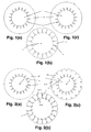
- Fig. 1 shows fundamental constituents of a fine channel device of the present invention.
- Fig. 1(a) shows a fluid supply device (3) having a fluid storage space (1) for supplying a liquid
- Fig. 1(b) shows a fine channel substrate (2) having Y-shaped fine channels (4) for performing a chemical treatment for a liquid or for producing fine droplets from the liquid
- Fig. 1(c) shows a fluid supply device (3) having a fluid storage space (1) for supplying a fluid.
- Fig. 2 shows two fluid supply devices and one fine channel substrate each having a perforated opening.
- Fig. 2(a) shows an example of fluid supply device (25) having a first fluid storage space (1) for supplying the first fluid, which has a perforated opening (8) formed in the fluid storage space.
- Fig. 2(b) is a fine channel substrate (2) having Y-shaped fine channels (4) for performing a chemical treatment for a liquid or for producing fine droplets from the liquid, which is an example having perforated openings (8) formed at two fluid inlet ports (6) of each of the fine channels and at a fluid outlet port (7) of each of the fine channels.
- Fig. 2 shows two fluid supply devices and one fine channel substrate each having a perforated opening.
- Fig. 2(a) shows an example of fluid supply device (25) having a first fluid storage space (1) for supplying the first fluid, which has a perforated opening (8) formed in the fluid storage space.
- Fig. 2(b) is a fine channel substrate (2) having
- FIG. 2(c) shows an example where a perforated opening (8) is formed in the fluid storage space of the fluid supply device (24) having a second fluid storage space (1) for supplying the second fluid, and where a perforated opening (8) is formed at a position corresponding to the position of a fluid outlet port of each of fine channels formed in the fine channel substrate.
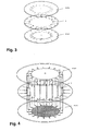
- Fig. 3 is a conceptual view of a fine channel substrate (2) having perforated openings shown in Fig. 2, sandwiched by a fluid supply device (25) having perforated openings for supplying a first fluid, and a fluid supply device (24) having perforated openings for supplying a second fluid, from the top and from the bottom respectively.
- Fig. 4 is a view showing the positional relationship of the perforated openings when the fine channel substrate (2) having perforated openings shown in Fig. 3, is sandwiched by the fluid supply device (25) having perforated openings for supplying the first fluid, and the fluid supply device (24) having perforated openings for supplying the second fluid from the top and bottom respectively.
- the fluid supply device (25) for supplying a first fluid, the fluid supply device (24) for supplying a second fluid, and the fine channel substrate (2) in Fig. 2 each capped, may be bonded together with sealing members such as O-rings.
- Figs. 5(a) to 5(d) are a perspective view and cross-sectional views of a fine channel device after it is bonded.
- Fig. 5(a) shows the fine channel device after bonded.
- Fig. 5(b), 5(c) and 5(d) show views in section A-A', section B-B' and section C-C' of the fine channel device of Fig. 5(a) respectively.
- supply channels (5) extending in a radial direction in the fluid supply device (25) on the top side for supplying the first fluid are each communicated with one of the fluid inlet ports (6) of a fine channel (4) formed in Y-shape in the fine channel substrate (2).
- supply channels (5) extending in a radial direction in the fluid supply device (24) on the bottom side for supplying the second fluid are each communicated with the other fluid inlet port (6) of a fine channel (4) formed in Y-shape in the fine channel substrate (2), a perforated opening (8) communicated with the fluid inlet port.
- a fluid outlet port (7) of the Y-shaped fine channel (4) formed in the fine channel substrate (2) is communicated with a perforated opening (8) of the fine channel substrate (2) communicated with the fluid outlet port and with the fluid outlet port (7) of the fluid supply device (24) for supplying the first fluid, whereby products produced in the fine channel can be discharged.
- the first fluid inlet port (10) and the second fluid inlet port (12) respectively communicated with a reservoir tank (9) for storing the first fluid and a reservoir tank (26) for storing the second fluid respectively provided in the fluid supply device (25) on the top side for supplying the first fluid and in the fluid supply device (24) on the bottom side for supplying the second fluid respectively, are formed as perforated openings, whereby it becomes possible to supply two types of fluids from the outside to the fine channel device of the present invention.
- the above-mentioned fine channel device is shown in order to describe the present invention in a easily understandable way.
- the shape and the number of reservoir tanks, the shape and the number of fine channels, the number of introduction channels of a fine channel and the number of discharge channels of a fine channel are not limited thereto.
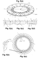
- Fig. 6(a) shows a case where the degree of integration of Y-shaped fine channels is increased, namely, a fine channel substrate having 100 fine channels. Further, Fig. 6(b) is an enlarged view of the circled portion in Fig. 6(a).
- Supply channels (5) extending in a radial direction from a reservoir tank (9) for storing the first fluid and a reservoir tank (26) for storing the second fluid respectively communicated with a first fluid inlet port (10) and a second fluid inlet port (12), have each a width gradually narrowing towards the periphery in order to improve the withstanding pressure of the cylindrical space and to improve the performance of removing bubbles.
- Fig. 8 is a view in an overlapping state, showing a fine channel device (11) constituted by a fine channel substrate having 100 fine channels sandwiched from the top and the bottom by a first fluid supply device and a second fluid supply device, as they are observed from the top.
- the fine channels, reservoir tanks and the supply channels shown in Figs. 6 to Fig. 8 were produced on a 5 inch Pyrex (trademark) substrate by employing common photolithography and wet etching processes.
- the fine channel substrate and the two fluid supply devices were bonded by commonly known fusion bonding. However, they may be connected via members such as O-rings as another bonding method.
- a plurality of tear-shaped reinforcement columns (14) are provided in the vicinity of the fluid inlet port.
- Fig. 9 is a schematic view showing an embodiment where the fine channel device of the present invention is incorporated in a fluid feeding system, and the fine channel device is connected with a fluid feeding pump (18) for a first fluid and with a fluid feeding pump (19) for a second fluid by means of capillary tubes (15) and flared fitting (21).
- the fine channel device is sandwiched by a substrate holder A (16) and a substrate holder B (17) and fixed by a fixing holder A (22) and a fixing holder B (23).
- the structure is such that the product can be taken out from the fluid outlet port of the fine channel device by a flared fitting (20) for discharging.
- the flared fitting (21) has a structure capable of introducing and discharging a fluid by a syringe member without leakage, and it is preferred to interpose an O-ring to minimize the leakage of the fluid.
- the flared fitting (21), the fixing holders (22) and (23), and substrate holders (16) and (17) are preferably made of a resin, a glass or a metal. Especially, in order to observe the internal status, they are preferably made of a transparent glass or a transparent resin.
- the desksize chemical plant of the present invention is a desksize chemical plant comprising a plurality of the fine channel devices, means for supplying at least one fluid to the plurality of fine channel devices, and means for recovering products formed by the chemical treatment of the fluid or fine particles formed by the fluid.
- the desksize chemical plant of the present invention is constituted by a raw material tank unit (28), a chemical plant unit (29) and a recovering tank unit (30).
- the chemical plant unit is characterized by comprising a plurality of the fine channel devices (11), means for supplying to the fine channel devices at least one fluid as a raw material of the products produced by a chemical treatment, or as a raw material for producing fine particles, and means for recovering products produced by the chemical treatment or particles produced in the plurality of fine channel devices.
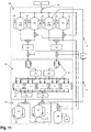
- the desksize chemical plant of the present invention is characterized by, as shown in Fig. 11, comprising a distributor (33) for facilitating to supply a fluid to a plurality of fine channel devices, and having a collector (34) for facilitating to recover products produced by performing a chemical treatment or fine particles produced in each of the fine channel devices.
- the fluid discharged after it is chemically treated can be taken out at a rate of 20 ⁇ L/min.
- 10 L of chemically treated fluid can be obtained even if the fluid is continuously flown into the fine channel without ceasing in full-year.
- the building size specifically means a building size of a few tens of meters square and a few meters high
- the desk size specifically means a desk size having a width of about 1 to 2 m, a depth of about 1 m and a height of about 1 to 2 m.
- the raw material tank unit shown in Fig. 11 has a raw material tanks (35) and a cleaning fluid tank 1 (48) and a cleaning fluid tank 2 (49), and the fluid is fed by a pressure-feeding type pump employing a gas supplied from an N 2 gas supplier (27).
- the raw material tank unit of the desksize chemical plant of the present invention is characterized by comprising a degassing device (32) shown in Fig. 11 used at a time of supplying the raw material.
- a degassing device 32 shown in Fig. 11 used at a time of supplying the raw material.
- the desksize chemical plant of the present invention comprises means for cleaning the fine channels constituting the fine channel device.
- a cleaning fluid tank 1 (48) and a cleaning fluid tank 2 (49) are provided in the raw material tank unit in Fig. 11, and a mechanism is provided for feeding the fluid in the regular direction of the feeding direction of the raw material fluid, or in the reverse direction of the feeding direction of the raw material fluid from the collector for recovering the products.
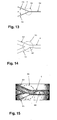
- the feeding route in the piping in a case of cleaning by feeding the fluid in the regular direction is shown in Fig. 12(a)
- the feeding route in the piping in a case of cleaning by feeding the fluid in the reverse direction is shown in Fig. 12(b).
- the fluid in this paragraph generally means a cleaning liquid.
- the desksize chemical plant of the present invention preferably comprises means for adjusting the fluid pressure produced in the fine channel devices so that it becomes possible to feed a fluid more uniformly.
- the desksize chemical plant of the present invention has, as shown in Fig. 11, a gas supply pipe (40) as means for supplying a gas to the fine channel device.
- the feeding route in the piping in a case of feeding the gas to the fine channel device is shown in Fig. 12(c).
- the desksize chemical plant of the present invention comprises in a raw material tank unit (28) as shown in Fig. 11, a raw material storage tanks (35) for storing a raw material liquid to be supplied to the fine channel device, and comprises in a recovering tank unit (30) a recovering tank (37) for recovering products produced by performing a chemical treatment for the fluid or fine particles produced in the fine channel device.
- the desksize chemical plant further comprises means for automatically supplying the raw material fluid to the raw material storage tank, and means for automatically feeding the products produced by performing a chemical treatment for the fluid or the particles produced in the fine channel device, from the recovering tank.
- the desksize chemical plant of the present invention further comprises, as shown in Fig. 11, a temporarily recovering tank (31) for temporarily storing the raw material discharged from the fine channel device other than the products in order to reuse at least one raw material among the raw materials for performing a chemical treatment or for producing fine particles, and a recovering pipe (41) as means for recovering the raw material to be reused from the above tank to the predetermined raw material tank (47) for storing the raw material, and further comprises a reuse-raw material separator/refiner (42) as means for separating and refining only the raw material to be reused from the raw material containing other raw materials and/or products of a chemical treatment or fine particles produced.
- a temporarily recovering tank (31) for temporarily storing the raw material discharged from the fine channel device other than the products in order to reuse at least one raw material among the raw materials for performing a chemical treatment or for producing fine particles
- a recovering pipe (41) as means for recovering the raw material to be reused from the above tank to the predetermined raw material tank (47) for storing the raw material
- an extremely expensive catalyst used for a heterogeneous system catalyst reaction as a chemical treatment for example, a chiral phase transfer catalyst having an effect to improve the optical selectivity in an asymmetric synthesis
- a chiral phase transfer catalyst having an effect to improve the optical selectivity in an asymmetric synthesis can be reused, whereby the cost can be reduced and the environmental impact can be reduced.
- the desksize chemical plant of the present invention further comprises, as shown in Fig. 11, a temperature control device (43) capable of controlling the temperature of the raw material tank (47), the recovering tank (37) and the fine channel devices, whereby stable supply of raw material fluid, and stable production and storage of products produced by performing a chemical reaction or particles produced in the fine channel device, can be achieved regardless of the place where the desksize chemical plant of the present invention is installed.
- a temperature control device (43) capable of controlling the temperature of the raw material tank (47), the recovering tank (37) and the fine channel devices, whereby stable supply of raw material fluid, and stable production and storage of products produced by performing a chemical reaction or particles produced in the fine channel device, can be achieved regardless of the place where the desksize chemical plant of the present invention is installed.
- a plurality of supply valves (44) for adjusting the quantity of the fluid supplied at a time of supplying a raw material fluid to each of the fine channel devices are provided for every one block of the fine channel devices, and for every fluid to be supplied.
- the desksize chemical plant of the present invention further comprises automatically controllable means in the process of at least one member selected from the group consisting of supplying raw material fluid to the fine channel device, recovering products produced by the chemical treatment or fine particles produced in the fine channel device, cleaning the fine channel device and drying the fine channel device.
- reference numeral 39 shows a vacuum pump.
- the fine particle producing apparatus of the present invention comprises means for supplying at least one fluid for producing fine particles to the fine channel device which constitutes the desksize chemical plant, and means for recovering the fine particles produced in the fine channel device, and is an apparatus for producing fine particles wherein the fluid for producing fine particles comprises a liquid containing a raw material for producing gel, and a liquid containing a dispersing agent for producing gel.
- the desksize chemical plant of the present invention can be specialized as a fine particle producing apparatus.
- the fine channel constituting the fine channel device has a Y-shape so that a dispersion phase and a continuous phase introduced from the respective inlet ports of the fine channel device are confluented in the fine channel to produce fine particles, wherein the angle at which the channel for introducing the dispersion phase crosses the channel for introducing the continuous phase is adjusted to control the size of fine particles produced.
- Fig. 9 is a conceptual view of an example of the present invention.
- the fine channel device (11) of the present invention shown in Fig. 9 is constructed such that a fluid supply device (24) of Fig. 7(b) for supplying a second fluid is bonded on the top side of the fine channel substrate (2) shown in Fig. 6(a), and a fluid supply device (25) of Fig. 7(a) for supplying a first fluid is bonded on a lower side to form the fine channel device (11) shown in Fig. 8 as a view observed from the top.
- Pyrex (tradename) substrates of 5 inch in diameter and 1.2 mm thick were employed.
- Fine channels formed on the fine channel substrate and reservoir tanks and supply channels were formed in the supply channel devices, by means of common photolithography and wet etching processes.
- the fine channel substrate and the fluid supply devices were bonded by means of common fusion bonding.
- Perforated openings of the fluid inlet ports of fine channels of the fine channel substrate, a perforated opening of the reservoir tank of the first fluid supply device, a perforated opening of the reservoir tank and perforated openings for fluid outlet ports of the second fluid supply device, were perforated openings each having a diameter of 1 mm formed by means of machining.
- 100 Y-shaped fine channels (4) were formed in the fine channel substrate (2), fluid inlet ports for introducing two fluids communicated with each of the fine channels were connected to fluid introduction ports of different fluid supply devices in order to introduce the respective fluids via supply channels (5) of a linear shape disposed in a radial direction from fluid storage spaces (1) provided in the two fluid supply devices connected on the top and lower side of the fine channel substrate.
- fluid inlet ports (10) for introducing the first fluid were disposed on a concentric circle having a radius of 35 mm
- fluid inlet ports (12) for introducing the second fluid were disposed on a concentric circle having a radius of 40 mm so that their positions in the radial direction were different.
- Fluid outlet ports (7) from the fine channels were disposed on a concentric circle having a radius of 55 mm.
- the fluid inlet ports were disposed so that two introduction channels were branched from each of the fluid inlet ports, and the fluid outlet ports were disposed so that two discharging channels were confluented at each of the fluid outlet ports.
- the fine channels formed inn the fine channel substrate have a width of 110 ⁇ m and a depth of 50 ⁇ m, and are each formed in a Y-shape in a space between from 40 mm to 55 mm in the radial direction from the center of the fine channel substrate.
- the angle of Y-shape formed by introduction channels was 44 degrees and the length of each of the fine channels from the confluenting point of the Y-shape to the fluid outlet port was 12 mm.
- Reservoir tanks formed in the fluid supply devices each has a diameter of 50 mm and a depth of 300 ⁇ m, and the shape of the reservoir tanks is a polygonal shape as shown in Fig. 7. From each of apex of the polygonal reservoir tank, a linear supply channel was formed in a radial direction towards the periphery.
- the supply channels from the reservoir tank of the first fluid supply device each has a length of 15 mm, a width of 1 mm and a depth of 300 ⁇ m
- the supply channels from the reservoir tank of the second fluid supply device each has a length of 20 mm, a width of 1 mm and a depth of 300 ⁇ m. 50 Supply channels were formed from the reservoir tank of each of the fluid supply devices. Further as shown in Fig.
- three tear-shaped reinforcement columns (14) each having a length of 5 mm, a maximum with of about 1 mm and a height equal to the depth of the reservoir tank, were formed in each reservoir tank on a circle having a radius of about 8 mm in the vicinity of the fluid inlet port at an interval of 120° on the concentric circle.
- the above-mentioned fine channel device (11) of the present invention was sandwiched by a substrate holder A (16) and a substrate holder B (17) to be fixed as shown in Fig. 9.
- a flared fitting (13) was connected to connect it to a first fluid-feeding pump (18) via a capillary tube (15) and introduce the first fluid to the fluid inlet port (10) for introducing the first fluid, which is communicated with a perforated opening communicated with a reservoir tank (9) for storing the first fluid in the fluid supply device (25) for supplying the first fluid.
- a flared fitting (21) was connected to connect it to a second fluid-feeding pump (19) via a capillary tube (15) and to introduce a second fluid into the second fluid inlet port (10) communicated with a perforated opening communicated with a reservoir tank (26) for storing the second fluid in the fluid supply device (24) for supplying the second fluid.
- 50 flared fittings (20) for discharging fluids were connected to respectively communicate with 50 fluid outlet ports each communicated with a perforated opening communicated with a fluid outlet port of each of the fine channels formed in the fine channel substrate and a perforated opening formed on the periphery side of the first fluid supply device. From these flared fittings for discharging fluids, fine droplets produced in the fine channels were discharged and recovered through capillary tubes.
- 3% of polyvinyl alcohol aqueous solution was fed to the fine channel device at a feeding rate of about 1.0 mL/min by the first fluid feeding pump, and a mixed solution of divinylbenzene and butyl acetate was fed to the fine channel device at a feeding rate of about 0.5 mL/min by the second fluid feeding pump.
- the two types of fluids were introduced to the respective fluid inlet ports provided to the reservoir tanks connected via the respective flared fittings for introducing the fluids.
- the two types of fluids introduced were temporarily stored in the respective reservoir tanks, introduced into the respective introducing channels of the Y-shaped fine channels formed in a Y-shape through supply channels extended in a radial direction from the reservoir tanks, and fine droplets were produced by shearing the mixed solution of divinylbenzene and butyl acetate as a dispersion phase by the polyvinyl alcohol aqueous solution as a continuous phase at the confluenting points of the Y-shaped fine channels.
- the fluid discharged from the 50 flared fittings for discharging communicated with the fluid outlet ports of the fine channels was recovered at each of the fluid outlet ports.
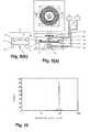
- 100 fine droplets contained in the recovered liquid 100 fine droplets were sampled to measure the distribution of the droplet size.
- the average size was about 100 ⁇ m and its distribution was within a range of from 5.6 to 7.3% with respect to each of the 50 fluid outlet ports. From this result, it was shown that by employing the fine channel device of the present invention, the liquid was supplied to each of the fine channels very evenly and under the same condition.
- the distribution of droplet size means a value obtained by dividing the standard deviation of the droplet size of the fine droplets sampled by the average droplet size, which is a reference value showing the width of the distribution of the droplet size.
- the liquid discharged from 50 liquid outlet ports was all recovered in the same sample bottle, and the 100 fine droplets recovered were sampled to measure the distribution of the droplet size of the fine droplets.
- the average droplet size was about 100 ⁇ m, its distribution was about 6.3%, which means that very uniform fine droplets were obtained by the fine channel device of the present invention as a whole.
- the fine particles were obtained at a production rate of 1.5 mL/min in a form of slurry.
- the fine droplets were produced by introducing 3% polyvinyl alcohol aqueous solution as a continuous phase and a mixture solution of divinylbenzene and butyl acetate as a dispersion phase, into a Y-shaped fine channel having the same shape as the Y-shaped fine channel employed in this Example, and by shearing the dispersion phase by the continuous phase at the confluenting point of the Y-shaped fine channel, then conditions under which the fine droplets having an average droplet size of about 100 ⁇ m and a droplet size distribution of within a range of from about 5 to 8% as the same level of the above Example, are such that the feeding speed of the continuous phase is about 10 ⁇ L/min, the feeding speed of the dispersion phase is about 5 ⁇ L/min, and the production rate of the slurry containing the fine droplets obtained by feeding the liquids is 15 ⁇ L/min.
- the fine channel device of this embodiment having 100 fine channels integrated, produces just about 100 times as much as the slurry produced by a single fine channel. Accordingly, it has been shown that by integrating fine channels by employing the fine channel device of the present invention, product having the same physical properties as that produced by a single fine channel can be produced in a large quantity depending on the number of the channels integrated.
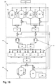
- Fig. 16 shows the construction of the fine particle producing apparatus of Example 2 of the present invention.
- it is constituted by an N 2 gas supplier (27), a raw material tank unit (28) for storing raw materials, a fine particle producing unit (45) constituted by five fine channel devices (11), a recover tank unit (30) for recovering fine particles produced or storing waste liquid at a time of cleaning, and pipes and valves for connecting them.
- the N 2 gas supplier supplies a N 2 gas via the pipes to a raw material tank 1 (46) and a raw material tank 2 (47) or to a cleaning fluid tank 1 (48) and a cleaning fluid tank 2 (49), whereby it becomes possible to supply the raw materials and the cleaning liquid.
- the raw material tank 1 stored a mixture of a monomer (styrene), butyl acetate and benzoyl peroxide as a dispersion phase
- the raw material tank 2 stored 3% polyvinyl alcohol aqueous solution as a continuous phase
- the cleaning fluid tank 1 stored ethanol as a cleaning liquid
- the cleaning tank 2 stored purified water as a cleaning liquid.
- the temperature of the raw material tank 1 and the raw material tank 2 can be controlled by a temperature control device (43).
- the fine particle production unit was constituted by five fine channel devices, but the number of the fine channel devices is not limited thereto.
- the fine particle producing unit further comprises distributors (33) for supplying each of the dispersion phase and the continuous phase to the five fine channel devices for producing fine particles, and a collector (34) for collecting fine particles produced in the five fine channel devices, and the pipes and valves for connecting them. Further, a degassing device (32) was provided between each of the raw material tanks and each of the distributors. Fine particles produced in the fine particle producing unit or waste liquid at a time of cleaning, were got together in the collector in the fine particle producing unit, and stored in the recovering tank (37) or in the waste liquid tank (38) connected via pipes and valves from the collector.
- the fine channel devices constituting the fine particle producing unit were each made of 5 inch Pyrex (tradename) glass substrate.
- 100 Y-shaped fine channels (4) were formed by common photolithography and wet etching processes in the Pyrex (tradename) glass substrate, and further, the fluid inlet ports (6) and fluid outlet ports (7) as perforated openings were formed at predetermined positions by machining to produce the fine channel substrate (2).
- the basic shape of the Y-shaped fine channel formed is shown in Fig. 13.
- the fine channel (4) having a protrusion (57) formed at the dispersion phase introducing channel side of the confluenting point (55) of the fine channel (4) was employed.
- each of the fine channels were formed to have, in the same manner as Example 1, a width of 110 ⁇ m and a depth of 50 ⁇ m, the protrusion was formed to have a convex portion of at most 25 ⁇ m towards inside of the channel and to have a length of 200 ⁇ m in the channel length direction.
- the Y-shaped fine channels were formed in the space between 40 mm to 55 mm in a radial direction from the center of the fine channel substrate and distributed in the peripheral direction of the disk-shaped fine channel substrate to have concentric distribution.
- the angle of Y-shape formed by the introduction channels was 44°, and the length of the fine channel from the confluenting point of the Y-shape to the fluid outlet port was 12 mm.
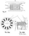
- Fig. 17 is a cross-sectional view showing one block of the fine channel devices of this embodiment.
- a cover substrate (50) having perforated openings formed at the predetermined positions and having the same shape as the fine channel substrate (2) was bonded to cover the surface of the fine channel substrate (2) where the fine channels were formed, by thermal bonding as a common method for bonding glasses.
- the reservoir tank (9) for storing the first fluid as the dispersion phase, the reservoir tank (26) for storing the second fluid as the continuous phase, and the supply channels (5) disposed in a radial direction for supplying raw materials to the Y-shaped microchannels, were formed by common photolithography and wet etching processes.
- cover substrates (50) each having perforated openings (8) formed by machining at predetermined positions and having the same shape as the fluid supply devices were bonded by fusion bonding as a common method for bonding glasses as shown in Fig 17.
- Raw materials were introduced through perforated openings (8) formed at the center of the fluid supply device (25) for supplying the first fluid and at the center of the fluid supply device (24) for supplying the second fluid.
- a fluid supply device (25) for supplying the first fluid and a fluid supply device (24) for supplying the second fluid were piled-up on its top and under sides.
- the above three fine channel substrates and two fluid supply devices disposed on the top and under sides of them were piled-up with preformed gaskets (52) having perforated openings at predetermined positions for sealing each space between the substrates. Further, all of the fine channel devices and the preformed gaskets were fixed by a fixing holder A (22) and a fixing holder B (23) made of metal to constitute a fine channel device (51) for producing fine particles shown in Fig. 17.
- Fig. 21 shows an overview of a fine particle producing apparatus comprising fine blocks of the above fine channel devices.
- the apparatus has a width of about 1.5 m, a depth of about 0.8 m and the height of about 1.4 m.
- continuous phase was fed at a feed rate of 1 L/hr and dispersion phase was fed at a feed rate of 0.5 L/hr from the respective raw material tanks by employing a pressure feeding pump for 10 hours (since the number of fine channels integrated in the fine channel apparatus is 1,500, the continuous phase was fed at a feed rate of 10 ⁇ L/min, and the dispersion phase was fed at a feed rate of about 5 ⁇ L/min to each of the fine channels).
- a slurry-formed liquid containing about 15 L of fine particles was obtained. This corresponds to a production capacity of producing the slurry-formed liquid containing about 5,000 L of fine particles by operating 10 hours a day for 1 year. This means that a production capacity comparable to a fine particles producing plant of building size in a scale of small to medium size was achieved in a desk size plant.
- Table 1 shows the average particle size and the distribution of the particles produced by the fine particle producing apparatus of Example 2, measured with respect to each of the five fine channel devices, and the average particle size and the distribution of the fine particles recovered from all of the five fine channel devices and measured together.
- the distribution of the fine particles was measured with respect to 100 fine particles sampled in the same manner as Example 1.
- the average particle size of the fine particles recovered from all of the five fine channel devices was 85.5 ⁇ m, and the distribution was 9.7%, which means fine particles having a very good distribution was obtained and a fine particle producing apparatus not requiring a classification process was achieved.
- a fine particle producing apparatus having a production capacity capable of producing several thousands of liter of fine particles contained in a slurry-formed fluid a year which is comparable to the production capacity of a fine particle producing plant of building size having a few meters high and a few tens of meters square, which is of a small to medium scale, and capable of producing fine particles having a very good distribution not requiring a classification process, was achieved by a desksize chemical plant of about 1.5 m wide, about 0.8 m deep and about 1.4 m high for the first time in the world.
- the fine particle producing apparatus comprised, as the fine particle producing unit, the chemical plant unit comprising five fine channel devices employing fine channel substrates each having Y-shaped fine channels formed.
- the desksize chemical plant for producing products produced by a chemical reaction in the fine channels can be constituted by fine channel devices constituted by fine channel substrates each having fine channels suitable for the chemical reaction instead of fine channel substrates having fine channels formed for producing fine particles.
- Fig. 18 shows an example of a fine channel substrate (2) having 12 fine channels (4) each formed to have two fluid inlet ports (6), two fluid outlet ports (7), a length of 20 cm, a width of 100 ⁇ m and a depth of 20 ⁇ m. Since it is necessary to maximize a time in which two fluids are in contact in the fine channels to proceed the chemical reaction, each of the fine channels has a shape turning eleven times in order to maximize the length of the fine channel, and the fine channels were integrated in a peripheral direction of the disk-shaped fine channel substrate.
- Fig. 19 shows an embodiment of a first fine channel substrate having fine channels (4) each having three fluid inlet ports (6) and three fluid outlet ports (7) wherein each of the fine channels has a length of 20 cm, a width of 150 ⁇ m and a depth of 20 ⁇ m, and 24 the fine channels (4) were formed in the fine channel substrate. Since it is necessary to maximize the time in which three fluids are in contact in the fine channels to perform a chemical reaction, each of the fine channels has a shape turning nineteen times in order to maximize the length of the fine channel, and the fine channels were integrated in the peripheral direction of the disk-shaped fine channel substrate.
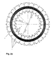
- Fig. 20 shows a second embodiment of the fine channel substrate having fine channels (4) each having three fluid inlet ports (6) and three fluid outlet ports (7).
- Each of the fine channels has a length of 20 cm, a width of 150 ⁇ m and a depth of 20 ⁇ m, and 24 the fine channels (4) were formed in the fine channel substrate (2). Since it is necessary to maximize the time in which three fluids are in contact to perform the chemical reaction, the longitudinal direction of the fine channels were formed in a circumferential direction of the disk-shaped fine channel substrate (2), and 24 of these fine channels were formed from the outer periphery towards the inner periphery to thereby maximize the length of the fine channels.
- the fluids not containing the product may be wasted. But by preparing for each of the fluids the pipe for recovering (41) shown in Fig. 11 and the reuse-raw material separator/refiner (42) for performing a treatment for the fluid to reuse a raw material, it becomes possible to perform a treatment to make them reusable as raw materials in the reuse-raw material separator/refiner, and return them to the raw material tanks to be reused as raw material, whereby it becomes possible to reduce the cost and the environmental impact.
- the fine channel device of the present invention is a fine channel device comprising at least one fluid inlet port for introducing at least one fluid, at least one fine channel for performing a chemical treatment of the fluid or for producing fine particles from the fluid, and at least one fluid outlet port for discharging at least one fluid applied with the chemical treatment or at least one fluid containing the fine particles produced;
- the fine channel device of the present invention comprises at least two fluid supply devices disposed on the top and under sides of at least one fine channel substrate lamination, whereby it becomes possible to supply at least two types of fluids so as to perform a chemical reaction or to produce fine particles into the fine channel substrate.
- the fine channel device of the present invention is a fine channel device which is constituted by piling-up at least two fine channel substrates having a fine channel for performing the chemical treatment or producing fine particles by the fluid, wherein each fluid inlet port for the fluid channel communicates with any one of the supply channels of the fluid supply device.
- the fine channel device of the present invention is a fine channel device wherein at least one introduced fluid can be introduced from the storage space of the fluid supply device into the fluid inlet port of the fine channel substrate having the fine channel independently. Also, it is a fine channel device wherein at least two supply channels of the fluid supply device are disposed so as not to overlap each of the supply channel of the fluid supply device. By such structure, it becomes possible to introduce different fluids into at least two introduction channels of fine channels formed in the fine channel substrate.
- the storage space communicating with each of the fine channels preferably has a shape of a circular or a polygonal recess.
- the storage space By making the storage space in such a shape, it becomes possible to supply the fluid to all fine channels formed in the fine channel substrate more uniformly.
- the shape of the storage space is a polygonal recess, as compared with a circular recess, there are effects of reducing the pressure loss at a time of feeding the fluid, and of promptly discharging bubbles remaining in the storage space when the fluid to be handled is a liquid.
- the desksize chemical plant of the present invention comprises a plurality of the fine channel devices, means for supplying at least one fluid to the plurality of fine channel devices, and means for recovering products produced by the chemical treatment for the fluid or fine particles produced from the fluid.
- a pump having little pulsation and little variation of the flow rate such as a pressure feeding type pump, can be employed, whereby the raw material fluid can be supplied to the plurality of fine channels constituting the plurality of fine channel devices at a stable feeding rate, and stable treatment to the fluid or stable production of fine particles becomes possible.
- the desksize chemical plant of the present invention comprises a degassing device for raw materials to be supplied, whereby it is possible to minimize bubbles mixed into the reservoir tanks for the plurality of fine channel devices, it is possible to remove the obstacle against uniform feeding of the fluid to each of the fine channels due to the bubbles in the reservoir tanks, and it is possible to further improve the stability in the chemical treatment for the fluids and in the production of fine particles.
- the desksize chemical plant of the present invention comprises a distributor for supplying a fluid to a plurality of the fine channel devices, and comprises a collector for recovering products produced by performing a chemical treatment or particles produced in the fine channel devices, whereby it is possible to simplify the structure of the piping arrangement for supplying raw material to the fine channel devices, for chemical treatment for the fluid in the fine channel devices or for producing fine particles.
- desksize chemical plant of the present invention comprises means for adjusting the fluid pressure produced in the fine channel device, whereby it becomes possible to feed a fluid into the fine channel device more uniformly.
- the desksize chemical plant of the present invention comprises a mechanism capable of flowing a cleaning liquid in the regular or the reverse direction with respect to the direction into which the raw material fluid is flown as means for cleaning fine channels constituting the fine channel devices, whereby it becomes possible to repeat flowing of the cleaning liquid in the regular and reverse directions to increase the effect of cleaning.
- the desksize chemical plant of the present invention comprises means for supplying a gas to the fine channel devices, whereby inside of the fine channels can be dried and maintained to be a clean state.
- the desksize chemical plant of the present invention comprises a raw material tank for storing a raw material fluid to be supplied to the fine channel device, and a recovering tank for recovering a product produced by performing a chemical treatment to the fluid or particles produced in the fine channel device.
- the desksize chemical plant further comprises means for automatically supplying the raw material fluid to the raw material tank, and means for automatically feeding from the recovering tank the product produced by performing the fluid or particles produced in the fine channel device, whereby long time continuous production becomes possible regardless of the quantity stored in the raw material tank or in the recovering tank.
- the desksize chemical plant of the present invention comprises a tank for temporarily storing the raw material discharged from the fine channels other than the products in order to reuse at least one of the raw materials for performing the chemical treatment or for producing the fine particles, and means for recovering the raw materials to be reused from the above tank to the tank for storing the raw material.
- the desksize chemical plant further comprises means for separating only the raw material to be reused from the raw material containing other raw materials and/or products of the chemical treatment or the fine particles produced, whereby, for example, it becomes possible to reuse a very expensive catalyst used for heterogeneous type catalyst reaction as a chemical treatment to reduce the cost and the environmental impact.
- the desksize chemical plant of the present invention comprises means capable of controlling the temperature of the raw material tank, the recovering tank and the fine channel device, whereby it is possible to supply the raw material fluid stably, and to produce and store the products produced by a chemical treatment or particles produced in the fine channel device.
- the desksize chemical plant of the present invention comprises a plurality of valves for every block of the fine channel devices and for every fluid to be supplied, for adjusting the quantity of the fluid supplied when the fluid is supplied to the fine channel device, whereby it becomes possible to adjust the supply rate of the raw material for each block of the fine channel devices and for each fluid to be supplied by controlling the plurality of valves, whereby it becomes possible to relatively freely control the conditions of the chemical treatment or the conditions for producing fine particles performed in the plurality of fine channels constituting the fine channel devices, and to finely control the flow rate.
- the desksize chemical plant of the present invention further comprises automatically controllable means used in at lest one process selected from the group consisting of supplying fluid to the fine channel device, recovering products produced by the chemical treatment or fine particles produced in the fine channel device, washing the fine channel device and the drying the fine channel device, whereby there is no troublesome operation required.
- the fine particle producing apparatus of the present invention is the desksize chemical plant comprising means for supplying at least one fluid for producing fine particles to a fine channel device and means for recovering the fine particles produced in the fine channel device, wherein the fluids for producing fine particles are a liquid containing a raw material for producing gel, and a liquid containing a dispersing agent for producing gel.
- the desksize chemical plant of the present invention can be used as a particle producing apparatus for producing gel.
- the fine particle producing apparatus of the present invention comprises a Y-shaped fine channel constituting a fine channel device so that a dispersion phase and a continuous phase introduced from the respective inlet ports of the fine channel device are confluented in the fine channel to produce fine particles, wherein the angle at which the channel for introducing the dispersion phase crosses the channel for introducing the continuous phase is adjusted to control the size of fine particles produced, whereby it becomes possible to produce particles of very uniform particle size having a distribution of particles of at most 10% in a large quantity and stably.
- Fine particle producing apparatus of the present invention, no classification process is required for separating particles having much different particle sizes after producing the particles, whereby it becomes possible to realize a desk size gel-producing apparatus for mass production comparable to a conventional gel production plant of building size, which is of a small to medium scale, and requiring no classification process.
- Average particle size and distribution of produced particles Average particle size ( ⁇ m) Distribution (%) Fine channel device 1 83.8 9.8 Fine channel device 2 85.2 9.2 Fine channel device 3 96.1 7.7 Fine channel device 4 86.8 9.9 Fine channel device 5 89.9 9.4 All fine channel devices (Fine particle producing apparatus) 85.5 9.7
- a fine channel device for performing a chemical treatment or for producing fine particles having the degree of integration of fine particles two-dimensionally and three-dimensionally and capable of supplying a liquid to all of the fine channels evenly and producing products in a large quantity, is provided, and a small-sized chemical plant capable of achieving a production quantity comparable to a conventional large-scale chemical plant comprising the fine channel device as a fundamental constituent factor, is provided.
- a fine channel device introducing at least one fluid and having fine channels for performing a chemical treatment for the fluid introduced and for producing particles from the fluid introduced, the fine channel device having a storage space for temporarily storing the introduced fluid having a shape of a circular or a polygonal recess, and supply channels of a linear and/or a curved shape formed in a radial direction from the storage space, wherein the fine channels are communicated with each of the fine channels of the fine channel substrate having the fine channels, is used.
- a small sized desksize chemical plant comprising a plurality of the fine channel devices as fundamental constituents, means for supplying at least one fluid to the plurality of fine channel devices, and means for recovering products produced by performing a chemical treatment of above fluid or particles produced from the above fluid in the plurality of fine channel devices, is used.
Landscapes
- Chemical & Material Sciences (AREA)
- Chemical Kinetics & Catalysis (AREA)
- Dispersion Chemistry (AREA)
- Organic Chemistry (AREA)
- Physical Or Chemical Processes And Apparatus (AREA)
- Devices And Processes Conducted In The Presence Of Fluids And Solid Particles (AREA)
Applications Claiming Priority (4)
| Application Number | Priority Date | Filing Date | Title |
|---|---|---|---|
| JP2002225104 | 2002-08-01 | ||
| JP2002225104 | 2002-08-01 | ||
| JP2002365666 | 2002-12-17 | ||
| JP2002365666 | 2002-12-17 |
Publications (3)
| Publication Number | Publication Date |
|---|---|
| EP1391237A2 true EP1391237A2 (de) | 2004-02-25 |
| EP1391237A3 EP1391237A3 (de) | 2006-03-22 |
| EP1391237B1 EP1391237B1 (de) | 2011-09-21 |
Family
ID=31190358
Family Applications (1)
| Application Number | Title | Priority Date | Filing Date |
|---|---|---|---|
| EP03017280A Expired - Lifetime EP1391237B1 (de) | 2002-08-01 | 2003-07-30 | Vorrichtung mit feinen Kanälen, miniaturisierte chemische Anlage zur Herstellung feiner Partikel und Vorrichtung zu dessen Verwendung |
Country Status (2)
| Country | Link |
|---|---|
| US (1) | US7338641B2 (de) |
| EP (1) | EP1391237B1 (de) |
Cited By (12)
| Publication number | Priority date | Publication date | Assignee | Title |
|---|---|---|---|---|
| WO2006134274A1 (fr) * | 2005-06-15 | 2006-12-21 | Rhodia Operations | Dispositif d'ecoulement microfluidique permettant de determiner des parametres d'une transformation physique et/ou chimique, et son utilisation |
| FR2887241A1 (fr) * | 2005-06-15 | 2006-12-22 | Rhodia Chimie Sa | Dispositif d'ecoulement microfluidique permettant de determiner des parametres d'une transformation physique et/ou chimique, et son utilisation |
| US7780929B2 (en) | 2006-03-28 | 2010-08-24 | Fujifilm Corporation | Fluid mixing apparatus and fluid mixing method |
| US7946037B2 (en) | 2007-09-28 | 2011-05-24 | Fujifilm Corporation | Microchemical device and method for fabricating the same |
| EP1641557A4 (de) * | 2003-06-06 | 2011-09-07 | Ehrfeld Mikrotechnik Bts Gmbh | Skalierbares dauerhaft betriebenes produktionssystem |
| EP2142314A4 (de) * | 2007-03-30 | 2012-04-25 | Fujifilm Corp | Verfahren zur reinigung von mikrofliesswegen |
| EP2289613A3 (de) * | 2009-08-24 | 2012-06-06 | Hitachi Plant Technologies, Ltd. | Emulgiermaschine und -verfahren |
| WO2015057998A1 (en) * | 2013-10-16 | 2015-04-23 | The University Of British Columbia | Device for formulating particles at small volumes |
| EP4159305A3 (de) * | 2021-09-10 | 2023-06-07 | Suzhou Precigenome Ltd, Co; | Mikrofluidisches nanopartikelsynthesesystem und vorrichtung und verfahren damit |
| EP4119221A4 (de) * | 2020-03-13 | 2024-04-17 | Japan Science and Technology Agency | Vorrichtung zur erzeugung von mikrotröpfchen/blasen |
| CN118925625A (zh) * | 2024-10-11 | 2024-11-12 | 浙江大学 | 一种用于液相脱氢或析氧反应的辐射状微反应器 |
| EP4537921A1 (de) * | 2023-10-13 | 2025-04-16 | Chanel Parfums Beauté | Mikrofluidisches hochdurchsatzextraktionssystem zur extraktion von natürlichen wirkstoffen |
Families Citing this family (9)
| Publication number | Priority date | Publication date | Assignee | Title |
|---|---|---|---|---|
| US20070053812A1 (en) * | 2003-03-07 | 2007-03-08 | Tosoh Corporation | Minute flow path structure body and die |
| WO2004082823A1 (ja) * | 2003-03-19 | 2004-09-30 | Tosoh Corporation | 微小流路構造体 |
| JP2006055770A (ja) * | 2004-08-20 | 2006-03-02 | Tosoh Corp | 微小流路構造体 |
| JP4449997B2 (ja) * | 2007-03-12 | 2010-04-14 | 株式会社日立製作所 | マイクロリアクタシステム |
| JP5636652B2 (ja) * | 2009-08-21 | 2014-12-10 | 富士ゼロックス株式会社 | 分級装置及び分級方法 |
| US8563325B1 (en) | 2009-09-29 | 2013-10-22 | Sandia Corporation | Coaxial microreactor for particle synthesis |
| WO2012008497A1 (ja) | 2010-07-13 | 2012-01-19 | 国立大学法人東京工業大学 | 微小液滴の製造装置 |
| CN103949170A (zh) * | 2014-05-04 | 2014-07-30 | 聊城大学 | 一种分流汇流型混合器及混合方法 |
| FR3154022B1 (fr) | 2023-10-13 | 2026-03-06 | Chanel Parfums Beaute | Distributeur pour système microfluidique |
Family Cites Families (13)
| Publication number | Priority date | Publication date | Assignee | Title |
|---|---|---|---|---|
| WO1998053311A2 (en) * | 1997-05-23 | 1998-11-26 | Gamera Bioscience Corporation | Devices and methods for using centripetal acceleration to drive fluid movement in a microfluidics system |
| US6167910B1 (en) * | 1998-01-20 | 2001-01-02 | Caliper Technologies Corp. | Multi-layer microfluidic devices |
| US6100541A (en) * | 1998-02-24 | 2000-08-08 | Caliper Technologies Corporation | Microfluidic devices and systems incorporating integrated optical elements |
| GB9809943D0 (en) * | 1998-05-08 | 1998-07-08 | Amersham Pharm Biotech Ab | Microfluidic device |
| EP1084391A4 (de) * | 1998-06-08 | 2006-06-14 | Caliper Life Sciences Inc | Mikrofluidische geräte, systeme und verfahren zur durchführung integrierter reaktionen und trennungen |
| JP2004529312A (ja) * | 1999-06-18 | 2004-09-24 | ガメラ バイオサイエンス コーポレイション | 小型化均一アッセイ用のデバイスおよび方法 |
| US6706519B1 (en) * | 1999-06-22 | 2004-03-16 | Tecan Trading Ag | Devices and methods for the performance of miniaturized in vitro amplification assays |
| US6537506B1 (en) * | 2000-02-03 | 2003-03-25 | Cellular Process Chemistry, Inc. | Miniaturized reaction apparatus |
| US6890093B2 (en) * | 2000-08-07 | 2005-05-10 | Nanostream, Inc. | Multi-stream microfludic mixers |
| US6623860B2 (en) * | 2000-10-10 | 2003-09-23 | Aclara Biosciences, Inc. | Multilevel flow structures |
| US7201873B2 (en) * | 2001-04-16 | 2007-04-10 | Tosoh Corporation | Fine channel device, method for producing the fine channel device and use of the same |
| US6791677B2 (en) * | 2001-08-28 | 2004-09-14 | Tosoh Corporation | Information measuring apparatus using a fine channel device |
| AU2002352735A1 (en) * | 2001-11-20 | 2003-06-10 | Burstein Technologies, Inc. | Optical bio-discs and microfluidic devices for analysis of cells |
-
2003
- 2003-07-30 EP EP03017280A patent/EP1391237B1/de not_active Expired - Lifetime
- 2003-07-31 US US10/630,847 patent/US7338641B2/en not_active Expired - Lifetime
Cited By (15)
| Publication number | Priority date | Publication date | Assignee | Title |
|---|---|---|---|---|
| EP1641557A4 (de) * | 2003-06-06 | 2011-09-07 | Ehrfeld Mikrotechnik Bts Gmbh | Skalierbares dauerhaft betriebenes produktionssystem |
| FR2887241A1 (fr) * | 2005-06-15 | 2006-12-22 | Rhodia Chimie Sa | Dispositif d'ecoulement microfluidique permettant de determiner des parametres d'une transformation physique et/ou chimique, et son utilisation |
| US7919323B2 (en) | 2005-06-15 | 2011-04-05 | Rhodia Operations | Microfluidic flow devices for determining parameters of physical and/or chemical transformations |
| WO2006134274A1 (fr) * | 2005-06-15 | 2006-12-21 | Rhodia Operations | Dispositif d'ecoulement microfluidique permettant de determiner des parametres d'une transformation physique et/ou chimique, et son utilisation |
| US7780929B2 (en) | 2006-03-28 | 2010-08-24 | Fujifilm Corporation | Fluid mixing apparatus and fluid mixing method |
| EP2142314A4 (de) * | 2007-03-30 | 2012-04-25 | Fujifilm Corp | Verfahren zur reinigung von mikrofliesswegen |
| US7946037B2 (en) | 2007-09-28 | 2011-05-24 | Fujifilm Corporation | Microchemical device and method for fabricating the same |
| EP2289613A3 (de) * | 2009-08-24 | 2012-06-06 | Hitachi Plant Technologies, Ltd. | Emulgiermaschine und -verfahren |
| WO2015057998A1 (en) * | 2013-10-16 | 2015-04-23 | The University Of British Columbia | Device for formulating particles at small volumes |
| US10159652B2 (en) | 2013-10-16 | 2018-12-25 | The University Of British Columbia | Device for formulating particles at small volumes |
| EP4119221A4 (de) * | 2020-03-13 | 2024-04-17 | Japan Science and Technology Agency | Vorrichtung zur erzeugung von mikrotröpfchen/blasen |
| EP4159305A3 (de) * | 2021-09-10 | 2023-06-07 | Suzhou Precigenome Ltd, Co; | Mikrofluidisches nanopartikelsynthesesystem und vorrichtung und verfahren damit |
| EP4537921A1 (de) * | 2023-10-13 | 2025-04-16 | Chanel Parfums Beauté | Mikrofluidisches hochdurchsatzextraktionssystem zur extraktion von natürlichen wirkstoffen |
| WO2025078673A1 (fr) * | 2023-10-13 | 2025-04-17 | Chanel Parfums Beaute | Système d'extraction microfluidique à haut rendement pour l'extraction d'actifs naturels |
| CN118925625A (zh) * | 2024-10-11 | 2024-11-12 | 浙江大学 | 一种用于液相脱氢或析氧反应的辐射状微反应器 |
Also Published As
| Publication number | Publication date |
|---|---|
| US7338641B2 (en) | 2008-03-04 |
| EP1391237B1 (de) | 2011-09-21 |
| US20040022690A1 (en) | 2004-02-05 |
| EP1391237A3 (de) | 2006-03-22 |
Similar Documents
| Publication | Publication Date | Title |
|---|---|---|
| EP1391237B1 (de) | Vorrichtung mit feinen Kanälen, miniaturisierte chemische Anlage zur Herstellung feiner Partikel und Vorrichtung zu dessen Verwendung | |
| JP4032128B2 (ja) | 微小流路構造体、構成されるデスクサイズ型化学プラント及びそれらを用いた微粒子製造装置 | |
| AU2007214340B2 (en) | Microchannel structure and fine-particle production method using the same | |
| CA1255074A (en) | Method and apparatus for contacting reactants in chemical and biological reactions | |
| AU708281B2 (en) | Integrated chemical synthesizers | |
| WO2006043642A1 (ja) | 流体反応装置 | |
| CN111957361A (zh) | 微滴制备系统、微流控芯片及其设计方法 | |
| CN106215990A (zh) | 一种规模化制备液滴的微流控模块 | |
| JP2023550090A (ja) | 生体細胞へのメカノポレーションベースのペイロード送達のための方法及びシステム | |
| CN109569755B (zh) | 液滴量产装置 | |
| CN110075934B (zh) | 一种3d打印微流控器件及其大通量制备单分散乳液的方法 | |
| US7413713B2 (en) | Reaction apparatus and mixing system | |
| JP2009166039A (ja) | 微粒子製造装置 | |
| CN1736577A (zh) | 一种多通道微结构反应器 | |
| JP4556849B2 (ja) | マイクロリアクタシステム | |
| CN219174499U (zh) | 一种基于聚焦微流控的数字pcr芯片 | |
| JP4352890B2 (ja) | 微粒子製造装置及びこれを利用した微粒子の製造方法 | |
| CN118304839A (zh) | 一种用于制备微乳液和杂环化合物的微通道反应器 | |
| JP2006055770A (ja) | 微小流路構造体 | |
| CN116672981A (zh) | 一种基于分形谢尔宾斯基三角形结构的微反应器及其用途和气液烯烃氢甲酰化反应的方法 | |
| CN206746525U (zh) | 一种自催化微反应器通道结构 | |
| US12145121B1 (en) | Flow control mechanism for high-throughput oligonucleotide synthesis | |
| CN113145190B (zh) | 一种用于多结构复合微液滴规模化可控制备的微流控装置 | |
| JP5211426B2 (ja) | マイクロリアクタシステム | |
| CN110465337B (zh) | 芯片及其液流控制方法和应用 |
Legal Events
| Date | Code | Title | Description |
|---|---|---|---|
| PUAI | Public reference made under article 153(3) epc to a published international application that has entered the european phase |
Free format text: ORIGINAL CODE: 0009012 |
|
| AK | Designated contracting states |
Kind code of ref document: A2 Designated state(s): AT BE BG CH CY CZ DE DK EE ES FI FR GB GR HU IE IT LI LU MC NL PT RO SE SI SK TR |
|
| AX | Request for extension of the european patent |
Extension state: AL LT LV MK |
|
| PUAL | Search report despatched |
Free format text: ORIGINAL CODE: 0009013 |
|
| AK | Designated contracting states |
Kind code of ref document: A3 Designated state(s): AT BE BG CH CY CZ DE DK EE ES FI FR GB GR HU IE IT LI LU MC NL PT RO SE SI SK TR |
|
| AX | Request for extension of the european patent |
Extension state: AL LT LV MK |
|
| 17P | Request for examination filed |
Effective date: 20060523 |
|
| 17Q | First examination report despatched |
Effective date: 20061013 |
|
| AKX | Designation fees paid |
Designated state(s): DE FR GB |
|
| GRAP | Despatch of communication of intention to grant a patent |
Free format text: ORIGINAL CODE: EPIDOSNIGR1 |
|
| GRAS | Grant fee paid |
Free format text: ORIGINAL CODE: EPIDOSNIGR3 |
|
| GRAA | (expected) grant |
Free format text: ORIGINAL CODE: 0009210 |
|
| AK | Designated contracting states |
Kind code of ref document: B1 Designated state(s): DE FR GB |
|
| REG | Reference to a national code |
Ref country code: GB Ref legal event code: FG4D |
|
| REG | Reference to a national code |
Ref country code: DE Ref legal event code: R096 Ref document number: 60338431 Country of ref document: DE Effective date: 20111110 |
|
| PLBE | No opposition filed within time limit |
Free format text: ORIGINAL CODE: 0009261 |
|
| STAA | Information on the status of an ep patent application or granted ep patent |
Free format text: STATUS: NO OPPOSITION FILED WITHIN TIME LIMIT |
|
| 26N | No opposition filed |
Effective date: 20120622 |
|
| REG | Reference to a national code |
Ref country code: DE Ref legal event code: R097 Ref document number: 60338431 Country of ref document: DE Effective date: 20120622 |
|
| REG | Reference to a national code |
Ref country code: FR Ref legal event code: PLFP Year of fee payment: 14 |
|
| REG | Reference to a national code |
Ref country code: FR Ref legal event code: PLFP Year of fee payment: 15 |
|
| REG | Reference to a national code |
Ref country code: FR Ref legal event code: PLFP Year of fee payment: 16 |
|
| PGFP | Annual fee paid to national office [announced via postgrant information from national office to epo] |
Ref country code: FR Payment date: 20190619 Year of fee payment: 17 |
|
| PGFP | Annual fee paid to national office [announced via postgrant information from national office to epo] |
Ref country code: DE Payment date: 20190716 Year of fee payment: 17 |
|
| PGFP | Annual fee paid to national office [announced via postgrant information from national office to epo] |
Ref country code: GB Payment date: 20190724 Year of fee payment: 17 |
|
| REG | Reference to a national code |
Ref country code: DE Ref legal event code: R119 Ref document number: 60338431 Country of ref document: DE |
|
| GBPC | Gb: european patent ceased through non-payment of renewal fee |
Effective date: 20200730 |
|
| PG25 | Lapsed in a contracting state [announced via postgrant information from national office to epo] |
Ref country code: FR Free format text: LAPSE BECAUSE OF NON-PAYMENT OF DUE FEES Effective date: 20200731 Ref country code: GB Free format text: LAPSE BECAUSE OF NON-PAYMENT OF DUE FEES Effective date: 20200730 |
|
| PG25 | Lapsed in a contracting state [announced via postgrant information from national office to epo] |
Ref country code: DE Free format text: LAPSE BECAUSE OF NON-PAYMENT OF DUE FEES Effective date: 20210202 |
|
| P01 | Opt-out of the competence of the unified patent court (upc) registered |
Effective date: 20230523 |