EP1892351A2 - Ausfachungsrahmen für eine Metallbaufassade - Google Patents
Ausfachungsrahmen für eine Metallbaufassade Download PDFInfo
- Publication number
- EP1892351A2 EP1892351A2 EP07113122A EP07113122A EP1892351A2 EP 1892351 A2 EP1892351 A2 EP 1892351A2 EP 07113122 A EP07113122 A EP 07113122A EP 07113122 A EP07113122 A EP 07113122A EP 1892351 A2 EP1892351 A2 EP 1892351A2
- Authority
- EP
- European Patent Office
- Prior art keywords
- frame
- ausfachungsrahmen
- legs
- facade
- infill
- Prior art date
- Legal status (The legal status is an assumption and is not a legal conclusion. Google has not performed a legal analysis and makes no representation as to the accuracy of the status listed.)
- Granted
Links
Images



Classifications
-
- E—FIXED CONSTRUCTIONS
- E04—BUILDING
- E04B—GENERAL BUILDING CONSTRUCTIONS; WALLS, e.g. PARTITIONS; ROOFS; FLOORS; CEILINGS; INSULATION OR OTHER PROTECTION OF BUILDINGS
- E04B2/00—Walls, e.g. partitions, for buildings; Wall construction with regard to insulation; Connections specially adapted to walls
- E04B2/88—Curtain walls
- E04B2/90—Curtain walls comprising panels directly attached to the structure
-
- E—FIXED CONSTRUCTIONS
- E04—BUILDING
- E04B—GENERAL BUILDING CONSTRUCTIONS; WALLS, e.g. PARTITIONS; ROOFS; FLOORS; CEILINGS; INSULATION OR OTHER PROTECTION OF BUILDINGS
- E04B2/00—Walls, e.g. partitions, for buildings; Wall construction with regard to insulation; Connections specially adapted to walls
- E04B2/88—Curtain walls
- E04B2/96—Curtain walls comprising panels attached to the structure through mullions or transoms
- E04B2/967—Details of the cross-section of the mullions or transoms
Definitions
- the invention relates to a Ausfachungsrahmen for a base frame with fillings mounted thereon metal construction facade.
- Metal construction facades are usually designed as element facades or mullion-transom facades.
- the fillings which are arranged in the base frame and usually consist of insulating glass panes, panels, stone slabs, etc., are generally used from the outside of the building into the frame construction. Accordingly, the retaining elements such as Glasandruckrucn or glazing beads are mounted from the outside of the building.
- both the retaining strips in element facades and the pressure strips at butt-transom facades have stumped.
- One reason for the usual blunt bumping is to be seen in the fact that the length adjustment of the retaining strips to the basic frame legs of the facade can be made relatively easily.
- the vertical strips run according to the vertical frame leg length.
- the horizontal bars only need to fit as closely as possible between them.
- miter-edged strips would have to be cut to length on all sides to match the basic frame legs so that a professional appearance is guaranteed. Since the base frame legs are also subject to relatively large dimensional tolerances, each individual bar would have to be fitted in practice. For economic For logistical reasons, solutions with mitred corners are therefore avoided wherever possible.
- the element frames should be dimensioned as large as possible for economic reasons, and on the other hand, for architectural reasons, the elements should be subdivided again by means of posts and bars, so that smaller infills arise.
- the element frames are clearly distinguishable from the posts and bars because of the different view widths and because of the joint pattern, so that the viewer shows an inhomogeneous appearance.
- blunt bumps such solutions often do not meet the requirements of contemporary architecture and aesthetics.
- the object underlying the invention is therefore to provide a Ausfachungsrahmen of the type mentioned above, with a metal facade, an individual look can be awarded, which shows the viewer an appearance as if each infill consist of an independent homogeneous component.
- the Ausfachungsrahmen invention has the significant advantage that can be produced in an economical manner expertly correct mitres and thus the positional and angular displacement of the abutting profiles can be easily maintained within the required tolerances.
- the Ausfachungsrahmen can be made all the same size regardless of the tolerances of the base frame, deviations resulting from powder and Eloxalbe harshungen are by the possibility of floating arrangement of Ausfachungsrahmen without adverse effect.
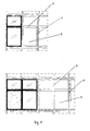
- Fig. 1 two examples of an element facade are shown, the base frame 1 is divided with fillings 3 by posts and bars 2 into smaller infills.
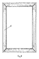
- the aim of the invention is to achieve an appearance, as shown in Fig. 2.
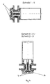
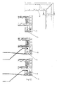
- 3 and 4 show the Ausfachungsrahmen invention in sectional views in an element facade or a mullion-transom facade.
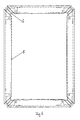
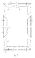
- the Ausfachungsrahmen invention consists of frame legs 5, which are interconnected via corner connectors 6 and are provided with means 10 for hooking the Ausfachungsrahmens on one leg of the base frame of the building facade.
- the latter devices 10 are shown in detail in FIGS. 3 and 4.
- the Ausfachungsrahmen invention is designed so that around each infill, a self-contained closed strip frame can be arranged floating, which hooks behind the corresponding web of the base frame.
- the Ausfachungsrahmen invention is slightly larger than the corresponding both in its width and in its height Dimensions of the base frame, so that the dimensional tolerances occurring on both frames are safe to handle.
- the Ausfachungsrahmen is assembled according to the invention only after the installation of the fillings by means of the corner connector 6.
- the frame legs 5 are prefixed by means of the corner connector 6 at a distance, as shown in Fig. 6.
- the corner connectors 6 at the ends of their legs far projecting webs 7, which spread out like a spring from the inside to the profile walls of the legs 5.
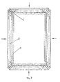
- the infill frame pre-set in this manner is laid on the base frame or infill in the manner shown in Fig. 7, whereupon the frame legs 5 are joined together at their ends. Thereafter, from the invisible inside a connecting pin 9 is driven with a special pliers, as shown in Fig. 9. In order to enable a secure prefixing of the connecting pin 9 in the profile, the profile wall is thickened at the pin plane, as it is also seen in Fig. 9.
- the holes 8 for the connecting pins 9 in the corner connectors 6 are offset from the corresponding holes in the legs 5 by a few tenths of a millimeter, so that when joining and connecting the legs 5 with the corner connectors 6, the cut surfaces of the mitered leg 5 with bias be pressed against each other.
- the embodiment of the invention is such that the connecting pin 9 is driven from the inside to the outside, while the outer glazing gasket is subsequently pressed.
- the infill frame can be dismantled without damage.
- Fig. 9 shows a further preferred possibility of assembling an embodiment of the Ausfachungsrahmen invention.
- not all legs 5 and corner connectors 6 are moved together from all four directions, but first the corner connectors 6 are preassembled with two frame legs 5 via a pin connection 9.
- the remaining frame members 5 are attached to the base frame and then the pre-assembled with corner connectors 6 frame legs 5 are inserted with the free ends of the corner connector 6 in the hollow chambers of the legs 5 and pushed together with them. This compound is subsequently pinned as well.
- the infill frame was part of the facade construction.
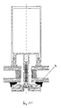
- Fig. 11 is an infill frame which is merely an imitation.
- the filling is in this case held by a pressure bar, as is customary in post-transom facades, while the Ausfachungsrahmen invention is placed only for optical reasons on conventional pressure bars.
Landscapes
- Engineering & Computer Science (AREA)
- Architecture (AREA)
- Physics & Mathematics (AREA)
- Electromagnetism (AREA)
- Civil Engineering (AREA)
- Structural Engineering (AREA)
- Load-Bearing And Curtain Walls (AREA)
- Finishing Walls (AREA)
- Conveying And Assembling Of Building Elements In Situ (AREA)
Abstract
Description
- Die Erfindung betrifft einen Ausfachungsrahmen für eine einen Grundrahmen mit daran angebrachten Füllungen aufweisende Metallbaufassade.
- Metallbaufassaden sind in der Regel als Elementfassaden oder Pfosten-Riegelfassaden ausgestaltet. Bei Metallbaufassaden sind die Füllungen, die im Grundrahmen angeordnet sind und in der Regel aus Isolierglasscheiben, Paneelen, Steinplatten usw. bestehen, grundsätzlich von der Gebäudeaußenseite her in die Rahmenkonstruktion eingesetzt. Dementsprechend sind auch die Halteelemente wie Glasandruckleisten oder Glasleisten von der Gebäudeaußenseite her angebracht.
- Ähnliches gilt für die Andruckleisten mit eventuell zusätzlichen Dekorprofilen, die bei Pfosten-Riegelfassaden vorgesehen sind.
- Diese Bauelemente haben vom Standpunkt der Architektur wegen der gestalterischen Möglichkeiten einen hohen Stellenwert. Von Bedeutung ist dabei sowohl die Einteilung der Grundrahmen als auch das Aussehen der Halteelemente im Einzelnen.
- Üblicherweise sind sowohl die Halteleisten bei Elementfassaden als auch die Andruckleisten bei Pfosten-Riegelfassaden stumpf gestoßen. Ein Grund für das übliche stumpfe Stoßen ist dabei darin zu sehen, dass die Längenabstimmung der Halteleisten zu den Grundrahmenschenkeln der Fassade relativ leicht vorgenommen werden kann. Die vertikalen Leisten laufen entsprechend der vertikalen Rahmenschenkellänge durch. Die horizontalen Leisten müssen lediglich möglichst genau dazwischenpassen.
- Auf Gehrung gearbeitete Leisten müssten im Gegensatz dazu allseitig passgenau zu den Grundrahmenschenkeln abgelängt sein, damit ein fachmännisches Erscheinungsbild gewährleistet ist. Da auch die Grundrahmenschenkel mit relativ großen Maßtoleranzen behaftet sind, müsste in der Praxis jede einzelne Leiste eingepasst werden. Aus wirtschaftlichen und logistischen Gründen werden deshalb Lösungen mit Gehrungsecken möglichst vermieden.
- Bei Metallbaufassaden besteht aus architektonischen Gründen oft der Wunsch an der Gebäudeaußenseite schmale Rahmen, welche mit Gehrungseckstößen ausgeführt sind, umlaufend um die einzelnen Ausfachungen anzuordnen. Damit soll der Eindruck vermittelt werden, dass jede Ausfachung mit ihrem Rahmen ein eigenständiges, homogenes Element darstellt, womit der Fassade ein individuelles Aussehen verliehen werden soll.
- Bei Elementfassaden bestehen weiterhin oft einander entgegenstehende Forderungen. Einerseits sollen die Elementrahmen aus wirtschaftlichen Gründen möglichst groß dimensioniert sein und andererseits sollen aus architektonischen Gründen die Elemente mittels Pfosten und Riegeln wieder unterteilt sein, damit kleinere Ausfachungen entstehen. Als Folge davon sind wegen der unterschiedlichen Ansichtsbreiten bzw. wegen des Fugenbildes die Elementrahmen von den Pfosten und Riegeln deutlich unterscheidbar, so dass sich dem Betrachter ein inhomogenes Erscheinungsbild zeigt. In Verbindung mit den genannten stumpfen Stößen, werden solche Lösungen den Ansprüchen zeitgemäßer Architektur und Ästhetik oftmals nicht gerecht.
- Die der Erfindung zugrunde liegende Aufgabe besteht daher darin, einen Ausfachungsrahmen der eingangs genannten Art zu schaffen, mit dem einer Metallbaufassade ein individuelles Aussehen verliehen werden kann, das dem Betrachter ein Erscheinungsbild zeigt, als bestünde jede Ausfachung aus einem eigenständigen homogenen Bauelement.
- Diese Aufgabe wird gemäß der Erfindung durch einen Ausfachungsrahmen gelöst, der im Patentanspruch 1 angegeben ist.
- Besonders bevorzugte Ausgestaltungen und Weiterbildungen des erfindungsgemäßen Ausfachungsrahmens sind Gegenstand der Patentansprüche 2 bis 6.
- Der erfindungsgemäße Ausfachungsrahmen hat den wesentlichen Vorteil, dass sich auf wirtschaftliche Weise fachmännisch korrekte Gehrungen herstellen lassen und somit der Lage- und Winkelversatz der stoßenden Profile leicht innerhalb der geforderten Toleranzen gehalten werden kann.
- Es gibt darüber hinaus keine besonderen Forderungen hinsichtlich der Zuschnitttoleranzen.
- Die Ausfachungsrahmen können unabhängig von den Toleranzen der Grundrahmen alle maßlich gleich gefertigt werden, Maßabweichungen, die sich infolge von Pulver- und Eloxalbeschichtungen ergeben, sind durch die Möglichkeit der schwimmenden Anordnung der Ausfachungsrahmen ohne nachteiligen Einfluss.
- Im Folgenden werden anhand der zugehörigen Zeichnungen besonders bevorzugte Ausführungsbeispiele der Erfindung näher beschrieben. Es zeigen:
- Fig. 1 ein Beispiel einer Elementfassade mit kleineren Ausfachungen,
- Fig. 2 eine Draufsicht auf die Anordnung von Ausfachungsrahmen gemäß der Erfindung,
- Fig. 3 Querschnittsansichten längs der Linien 1-1, 2-2 und 3-3 in Fig. 2 bei einer Elementfassade,
- Fig. 4 Querschnittsansichten längs den Linien 1-1, 2-2 und 3-3 in Fig. 2 bei einer Pfosten-Riegelfassade,
- Fig. 5, 6, 7 und 8 die Montage eines erfindungsgemäßen Ausfachungsrahmens am Grundrahmen einer Gebäudefassade,
- Fig. 9 in einer Fig. 5 entsprechenden Ansicht eine weitere bevorzugte Art des Zusammenbaus eines erfindungsgemäßen Ausfachungsrahmens
- Fig. 10 in Querschnittsansichten die Befestigung der Rahmenschenkel an den Eckverbindern bei einem Ausführungsbeispiel des erfindungsgemäßen Ausfachungsrahmens und
- Fig. 11 in einer Querschnittsansicht ein weiteres Ausführungsbeispiel eines erfindungsgemäßen Ausfachungsrahmens.
- In Fig. 1 sind zwei Beispiele einer Elementfassade dargestellt, deren Grundrahmen 1 mit Füllungen 3 durch Pfosten und Riegel 2 in kleinere Ausfachungen unterteilt ist.
- Aus den bereits angegebenen Gründen sind die Pfosten und Riegel 2 deutlich von den Grundrahmen 1 zu unterscheiden, was ein inhomogenes Erscheinungsbild ergibt.
- Ziel der Erfindung ist es, ein Erscheinungsbild zu erzielen, wie es in Fig. 2 dargestellt ist.
- Dieses Ziel wird gemäß der Erfindung durch einen Ausfachungsrahmen 4 erreicht, der in Fig. 2 dargestellt ist.
- Fig. 3 und 4 zeigen den erfindungsgemäßen Ausfachungsrahmen in Schnittansichten bei einer Elementfassade bzw. einer Pfosten-Riegelfassade.
- Wie es in Fig. 5 im Einzelnen dargestellt ist, besteht der erfindungsgemäße Ausfachungsrahmen aus Rahmenschenkeln 5, die über Eckverbinder 6 miteinander verbunden sind und mit Einrichtungen 10 zum Hinterhaken des Ausfachungsrahmens an einem Schenkel des Grundrahmens der Gebäudefassade versehen sind. Letztere Einrichtungen 10 sind in den Figuren 3 und 4 im Einzelnen dargestellt.
- Der erfindungsgemäße Ausfachungsrahmen ist so ausgebildet, dass um jede Ausfachung ein eigenständiger geschlossener Leistenrahmen schwimmend angeordnet werden kann, der an dem entsprechenden Steg des Grundrahmens hinterhakt.
- Der erfindungsgemäße Ausfachungsrahmen ist sowohl in seiner Breite als auch in seiner Höhe geringfügig größer als die entsprechenden Abmessungen des Grundrahmens, so dass die an beiden Rahmen auftretenden Maßtoleranzen sicher beherrschbar sind.
- Wie es in den Figuren 5 bis 8 im Einzelnen dargestellt ist, wird der Ausfachungsrahmen gemäß der Erfindung erst nach dem Einbau der Füllungen mittels der Eckverbinder 6 zusammengefügt. Zunächst werden die Rahmenschenkel 5 mittels der Eckverbinder 6 auf Distanz vorgefügt, wie es in Fig. 6 dargestellt ist. Dazu haben die Eckverbinder 6 an den Enden ihrer Schenkel weit vorragende Stege 7, welche sich federartig von innen an die Profilwände der Schenkel 5 spreizen.
- Der in dieser Weise vorgefügte Ausfachungsrahmen wird in der in Fig. 7 dargestellten Weise auf den Grundrahmen bzw. auf die Ausfachung gelegt, woraufhin die Rahmenschenkel 5 an ihren Enden zusammengefügt werden. Danach wird von der nicht sichtbaren Innenseite ein Verbindungsstift 9 mit einer Spezialzange eingetrieben, wie es in Fig. 9 dargestellt ist. Um dabei eine sichere Vorfixierung des Verbindungsstiftes 9 im Profil zu ermöglichen, ist die Profilwand an der Stiftebene verdickt, wie es gleichfalls in Fig. 9 erkennbar ist.
- Der fertige Montagezustand ist in Fig. 8 dargestellt.
- Die Bohrungen 8 für die Verbindungsstifte 9 in den Eckverbindern 6 sind zu den entsprechenden Bohrungen in den Schenkeln 5 um wenige Zehntel Millimeter versetzt angeordnet, so dass beim Zusammenfügen und Verbinden der Schenkel 5 mit den Eckverbindern 6 die Schnittflächen der auf Gehrung geschnittenen Schenkel 5 mit Vorspannung gegeneinander gepresst werden.
- Die erfindungsgemäße Ausgestaltung ist derart, dass der Verbindungsstift 9 von innen nach außen eingetrieben wird, während die äußere Verglasungsdichtung nachträglich eingedrückt wird.
- Mittels der Dichtungen zwischen den Ausfachungsrahmen kann dann ein individuelles Fugenbild geschaffen werden, das dem Ausfachungsrahmen ein sehr schlankes Aussehen gibt.
- Nach dem Eindrücken der Verbindungsstifte 9 in die Eckverbinder 6 kann weiterhin der Ausfachungsrahmen von außen nicht mehr abgenommen werden, ohne ihn zu zerstören. Im Vergleich zu üblichen Konstruktionen ergibt sich dadurch eine erhöhte Einbruchhemmung.
- Wenn eine zersprungene Füllung, beispielsweise eine zersprungene Glasscheibe ausgetauscht werden muss, besteht nach Entfernen aller Bruchstücke Zugang zu den Verbindungsstiften 9. Dadurch lässt sich in diesem Fall der Ausfachungsrahmen unbeschadet demontieren.
- Fig. 9 zeigt eine weitere bevorzugte Möglichkeit des Zusammenbaus eines Ausführungsbeispiels des erfindungsgemäßen Ausfachungsrahmen. Dabei werden im Gegensatz zu der in Fig. 5 dargestellten Art des Zusammenbaus nicht alle Schenkel 5 und Eckverbinder 6 aus allen vier Richtungen zusammengefahren sondern werden zunächst die Eckverbinder 6 mit zwei Rahmenschenkeln 5 über eine Stiftverbindung 9 vormontiert.
- Bei diesem Zusammenbau werden die verbleibenden Rahmenschenkel 5 an den Grundrahmen angebracht und werden dann die bereits mit Eckverbindern 6 vormontierten Rahmenschenkel 5 mit den freien Enden der Eckverbinder 6 in die Hohlkammern der Schenkel 5 eingesteckt und mit diesen zusammengeschoben. Diese Verbindung wird anschließend gleichfalls verstiftet.
- Bei dem in den Figuren 1 bis 10 dargestellten Ausführungsbeispiel war der Ausfachungsrahmen Teil der Fassadenkonstruktion.
- Das in Fig. 11 dargestellte Ausführungsbeispiel ist ein Ausfachungsrahmen, der lediglich eine Imitation darstellt. Die Füllung ist hierbei von einer Andruckleiste gehalten, wie es bei Pfosten-Riegelfassaden üblich ist, während der erfindungsgemäße Ausfachungsrahmen lediglich aus optischen Gründen auf konventionelle Andruckleisten aufgesetzt ist.
Claims (6)
- Ausfachungsrahmen für eine einen Grundrahmen mit daran angebrachten Füllungen aufweisende Metallbaufassade, gekennzeichnet durch Rahmenschenkel, die über Eckverbinder miteinander verbunden sind, und Einrichtungen zum Hinterhaken des Ausfachungsrahmens an einem Schenkel des Grundrahmens der Metallbaufassade.
- Ausfachungsrahmen nach Anspruch 1, dadurch gekennzeichnet, dass die Rahmenschenkel auf Gehrung geschnitten sind.
- Ausfachungsrahmen nach Anspruch 1 oder 2, dadurch gekennzeichnet, dass die Abmessungen der Rahmenschenkel größer als die Abmessungen der Schenkel des Grundrahmens sind.
- Ausfachungsrahmen nach einem der Ansprüche 1 bis 3, dadurch gekennzeichnet, dass die Rahmenschenkel und die Eckverbinder über Verbindungsstifte miteinander verbunden sind.
- Ausfachungsrahmen nach Anspruch 4, dadurch gekennzeichnet, dass die Verbindungsstifte von der Gehäuseinnenseite zur Gehäuseaußenseite eingetrieben sind.
- Ausfachungsrahmen nach Anspruch 4, dadurch gekennzeichnet, dass die Bohrungen für die Verbindungsstifte in den Rahmenschenkeln und den Eckverbindern jeweils zueinander versetzt angeordnet sind.
Priority Applications (1)
| Application Number | Priority Date | Filing Date | Title |
|---|---|---|---|
| PL07113122T PL1892351T3 (pl) | 2006-08-07 | 2007-07-25 | Ramka wypełniająca szkielet ściany dla metalowej elewacji budowlanej |
Applications Claiming Priority (1)
| Application Number | Priority Date | Filing Date | Title |
|---|---|---|---|
| DE102006036842A DE102006036842A1 (de) | 2006-08-07 | 2006-08-07 | Ausfachungsrahmen für eine Metallbaufassade |
Publications (3)
| Publication Number | Publication Date |
|---|---|
| EP1892351A2 true EP1892351A2 (de) | 2008-02-27 |
| EP1892351A3 EP1892351A3 (de) | 2010-12-29 |
| EP1892351B1 EP1892351B1 (de) | 2013-11-06 |
Family
ID=38669346
Family Applications (1)
| Application Number | Title | Priority Date | Filing Date |
|---|---|---|---|
| EP07113122.1A Not-in-force EP1892351B1 (de) | 2006-08-07 | 2007-07-25 | Ausfachungsrahmen für eine Metallbaufassade |
Country Status (3)
| Country | Link |
|---|---|
| EP (1) | EP1892351B1 (de) |
| DE (1) | DE102006036842A1 (de) |
| PL (1) | PL1892351T3 (de) |
Cited By (3)
| Publication number | Priority date | Publication date | Assignee | Title |
|---|---|---|---|---|
| GB2435652B (en) * | 2006-03-02 | 2008-11-19 | Architectural & Metal Systems | Walling system |
| WO2010043862A3 (en) * | 2008-10-15 | 2010-08-26 | Ove Arup & Partners International Ltd | Facade system for buildings |
| DE102009023883A1 (de) * | 2009-06-04 | 2010-12-16 | Schindler Fenster Fassaden Innenausbau GmbH & Co. KG | Fassadenelement |
Families Citing this family (3)
| Publication number | Priority date | Publication date | Assignee | Title |
|---|---|---|---|---|
| DE102008030786A1 (de) | 2008-06-28 | 2009-12-31 | Hydro Aluminium As | Ausfachungsrahmen für Gebäudefassaden |
| DE102010034051A1 (de) * | 2010-08-11 | 2012-02-16 | Röder HTS Höcker GmbH | System zur variablen Gestaltung einer Fensterfassade und ein Verfahren zur Herstellung einer Fensterfassade |
| US10208483B1 (en) * | 2017-08-01 | 2019-02-19 | SkyStone Group LLC | Façades of modular units and methods of construction thereof |
Family Cites Families (7)
| Publication number | Priority date | Publication date | Assignee | Title |
|---|---|---|---|---|
| US4295305A (en) * | 1975-06-09 | 1981-10-20 | Shelver Lyle N | Thermal glass structure and method for forming same |
| CH630991A5 (en) * | 1978-04-18 | 1982-07-15 | Schweizer Ernst Ag Metallbau Z | Composite profile |
| DE3828010A1 (de) * | 1988-08-18 | 1990-02-22 | Wolfgang D Zapp | Fenster- oder tuerfluegel |
| DE4021650C2 (de) * | 1990-07-07 | 1994-03-10 | Johann Weiherer | Vorrichtung zur Befestigung von Mehrscheiben-Isolierglas |
| DE9311567U1 (de) * | 1993-08-03 | 1993-11-11 | Sälzer Sicherheitstechnik GmbH, 35041 Marburg | Tür oder Fenster |
| EP0821127A3 (de) * | 1996-07-23 | 1998-09-16 | Ulrich Knak | Vorrichtung zur thermisch isolierten Befestigung von flachen Bauelementen |
| ITTS20030008A1 (it) * | 2003-03-18 | 2004-09-19 | Alprogetti Srl | Sistema di connessione sui montanti di ante, |
-
2006
- 2006-08-07 DE DE102006036842A patent/DE102006036842A1/de not_active Withdrawn
-
2007
- 2007-07-25 PL PL07113122T patent/PL1892351T3/pl unknown
- 2007-07-25 EP EP07113122.1A patent/EP1892351B1/de not_active Not-in-force
Cited By (4)
| Publication number | Priority date | Publication date | Assignee | Title |
|---|---|---|---|---|
| GB2435652B (en) * | 2006-03-02 | 2008-11-19 | Architectural & Metal Systems | Walling system |
| WO2010043862A3 (en) * | 2008-10-15 | 2010-08-26 | Ove Arup & Partners International Ltd | Facade system for buildings |
| DE102009023883A1 (de) * | 2009-06-04 | 2010-12-16 | Schindler Fenster Fassaden Innenausbau GmbH & Co. KG | Fassadenelement |
| DE102009023883B4 (de) * | 2009-06-04 | 2019-01-24 | Schindler Fenster + Fassaden Gmbh | Fassadenelement |
Also Published As
| Publication number | Publication date |
|---|---|
| DE102006036842A1 (de) | 2008-02-14 |
| EP1892351B1 (de) | 2013-11-06 |
| EP1892351A3 (de) | 2010-12-29 |
| PL1892351T3 (pl) | 2014-04-30 |
Similar Documents
| Publication | Publication Date | Title |
|---|---|---|
| AT402080B (de) | Fassadenverkleidung für die aussenseite von gebäuden | |
| EP1892351B1 (de) | Ausfachungsrahmen für eine Metallbaufassade | |
| EP2910699B1 (de) | Kantenprofilelementanordnung | |
| EP0569654A1 (de) | Alu-Holz-Verbundprofil für die Herstellung von Fenstern, daraus hergestelltes Fenster und Verfahren zur Herstellung eines solchen Fensters | |
| EP3910156B1 (de) | Insekten- und/oder pollenschutzgitter | |
| EP0221480B1 (de) | Fassadenwand | |
| DE2656958A1 (de) | Eckverbindung von auf gehrung geschnittenen profilen | |
| DE102006061655A1 (de) | Wärmedämmleiste | |
| DE69004954T2 (de) | Ausbildung einer eckfuge für baueinheiten aus stein. | |
| DE3201833C2 (de) | Eckwinkel aus Stanzblech zur Verbindung von Abstandhalter-Hohlprofilen für Isolierverglasungen | |
| DE202005021480U1 (de) | Verbindungselemente für Platten, insbesondere aus Glas, zur Befestigung derselben und derart ausgerüstete Platten | |
| DE2519457A1 (de) | Luftbehandlungsvorrichtung, insbesondere lueftungs- oder klimageraet | |
| EP2418335A2 (de) | System zur variablen Gestaltung einer Fensterfassade und ein Verfahren zur Herstellung einer Fensterfassade | |
| AT408124B (de) | Eckverbinder für fenster | |
| EP3670806A1 (de) | Verfahren zum befestigen eines profils an einem stab | |
| EP4191012B1 (de) | Gebäudeöffnungs-schliesselement und verfahren zu seiner herstellung | |
| EP2251521A2 (de) | Profilverbinder, Profilrahmen und Insektenschutzgitter | |
| DE102017202931B4 (de) | Profil zum Erstellen von Aufbauten und Aufbau mit wenigstens zwei Profilen | |
| DE2313317C3 (de) | Eckverbindung für die Schenkel von Fensterblendrahmen | |
| EP1262622A2 (de) | Hinterlegungsbauteil | |
| EP1491696A2 (de) | Profilverbindungssystem | |
| AT520136B1 (de) | DAS SYSTEM DER AUßENJALOUSIE MIT INSEKTENSCHUTZ FÜR EINBAU IN DEN RAHMEN VORHANDENER FENSTER ODER TÜREN UND DAS DAMIT VERBUNDENE VERFAHREN | |
| DE3248236A1 (de) | Rahmen fuer fenster oder mit fuellungen oder verglasungen versehene tueren | |
| EP2450496B1 (de) | Dichtelement | |
| EP0545024A1 (de) | Abstandhalterrahmen für Isolierverglasungen |
Legal Events
| Date | Code | Title | Description |
|---|---|---|---|
| PUAI | Public reference made under article 153(3) epc to a published international application that has entered the european phase |
Free format text: ORIGINAL CODE: 0009012 |
|
| AK | Designated contracting states |
Kind code of ref document: A2 Designated state(s): AT BE BG CH CY CZ DE DK EE ES FI FR GB GR HU IE IS IT LI LT LU LV MC MT NL PL PT RO SE SI SK TR |
|
| AX | Request for extension of the european patent |
Extension state: AL BA HR MK YU |
|
| PUAL | Search report despatched |
Free format text: ORIGINAL CODE: 0009013 |
|
| AK | Designated contracting states |
Kind code of ref document: A3 Designated state(s): AT BE BG CH CY CZ DE DK EE ES FI FR GB GR HU IE IS IT LI LT LU LV MC MT NL PL PT RO SE SI SK TR |
|
| AX | Request for extension of the european patent |
Extension state: AL BA HR MK RS |
|
| 17P | Request for examination filed |
Effective date: 20110629 |
|
| AKX | Designation fees paid |
Designated state(s): AT BE BG CH CY CZ DE DK EE ES FI FR GB GR HU IE IS IT LI LT LU LV MC MT NL PL PT RO SE SI SK TR |
|
| GRAP | Despatch of communication of intention to grant a patent |
Free format text: ORIGINAL CODE: EPIDOSNIGR1 |
|
| INTG | Intention to grant announced |
Effective date: 20130503 |
|
| GRAS | Grant fee paid |
Free format text: ORIGINAL CODE: EPIDOSNIGR3 |
|
| GRAA | (expected) grant |
Free format text: ORIGINAL CODE: 0009210 |
|
| AK | Designated contracting states |
Kind code of ref document: B1 Designated state(s): AT BE BG CH CY CZ DE DK EE ES FI FR GB GR HU IE IS IT LI LT LU LV MC MT NL PL PT RO SE SI SK TR |
|
| REG | Reference to a national code |
Ref country code: GB Ref legal event code: FG4D Free format text: NOT ENGLISH |
|
| REG | Reference to a national code |
Ref country code: CH Ref legal event code: EP |
|
| REG | Reference to a national code |
Ref country code: AT Ref legal event code: REF Ref document number: 639614 Country of ref document: AT Kind code of ref document: T Effective date: 20131215 |
|
| REG | Reference to a national code |
Ref country code: IE Ref legal event code: FG4D Free format text: LANGUAGE OF EP DOCUMENT: GERMAN |
|
| REG | Reference to a national code |
Ref country code: DE Ref legal event code: R096 Ref document number: 502007012460 Country of ref document: DE Effective date: 20140102 |
|
| REG | Reference to a national code |
Ref country code: NL Ref legal event code: VDEP Effective date: 20131106 |
|
| REG | Reference to a national code |
Ref country code: LT Ref legal event code: MG4D |
|
| PG25 | Lapsed in a contracting state [announced via postgrant information from national office to epo] |
Ref country code: NL Free format text: LAPSE BECAUSE OF FAILURE TO SUBMIT A TRANSLATION OF THE DESCRIPTION OR TO PAY THE FEE WITHIN THE PRESCRIBED TIME-LIMIT Effective date: 20131106 Ref country code: SE Free format text: LAPSE BECAUSE OF FAILURE TO SUBMIT A TRANSLATION OF THE DESCRIPTION OR TO PAY THE FEE WITHIN THE PRESCRIBED TIME-LIMIT Effective date: 20131106 Ref country code: LT Free format text: LAPSE BECAUSE OF FAILURE TO SUBMIT A TRANSLATION OF THE DESCRIPTION OR TO PAY THE FEE WITHIN THE PRESCRIBED TIME-LIMIT Effective date: 20131106 Ref country code: FI Free format text: LAPSE BECAUSE OF FAILURE TO SUBMIT A TRANSLATION OF THE DESCRIPTION OR TO PAY THE FEE WITHIN THE PRESCRIBED TIME-LIMIT Effective date: 20131106 Ref country code: IS Free format text: LAPSE BECAUSE OF FAILURE TO SUBMIT A TRANSLATION OF THE DESCRIPTION OR TO PAY THE FEE WITHIN THE PRESCRIBED TIME-LIMIT Effective date: 20140306 |
|
| REG | Reference to a national code |
Ref country code: PL Ref legal event code: T3 |
|
| PG25 | Lapsed in a contracting state [announced via postgrant information from national office to epo] |
Ref country code: ES Free format text: LAPSE BECAUSE OF FAILURE TO SUBMIT A TRANSLATION OF THE DESCRIPTION OR TO PAY THE FEE WITHIN THE PRESCRIBED TIME-LIMIT Effective date: 20131106 Ref country code: LV Free format text: LAPSE BECAUSE OF FAILURE TO SUBMIT A TRANSLATION OF THE DESCRIPTION OR TO PAY THE FEE WITHIN THE PRESCRIBED TIME-LIMIT Effective date: 20131106 |
|
| PG25 | Lapsed in a contracting state [announced via postgrant information from national office to epo] |
Ref country code: PT Free format text: LAPSE BECAUSE OF FAILURE TO SUBMIT A TRANSLATION OF THE DESCRIPTION OR TO PAY THE FEE WITHIN THE PRESCRIBED TIME-LIMIT Effective date: 20140306 |
|
| PG25 | Lapsed in a contracting state [announced via postgrant information from national office to epo] |
Ref country code: EE Free format text: LAPSE BECAUSE OF FAILURE TO SUBMIT A TRANSLATION OF THE DESCRIPTION OR TO PAY THE FEE WITHIN THE PRESCRIBED TIME-LIMIT Effective date: 20131106 |
|
| REG | Reference to a national code |
Ref country code: DE Ref legal event code: R097 Ref document number: 502007012460 Country of ref document: DE |
|
| PG25 | Lapsed in a contracting state [announced via postgrant information from national office to epo] |
Ref country code: IT Free format text: LAPSE BECAUSE OF FAILURE TO SUBMIT A TRANSLATION OF THE DESCRIPTION OR TO PAY THE FEE WITHIN THE PRESCRIBED TIME-LIMIT Effective date: 20131106 Ref country code: SK Free format text: LAPSE BECAUSE OF FAILURE TO SUBMIT A TRANSLATION OF THE DESCRIPTION OR TO PAY THE FEE WITHIN THE PRESCRIBED TIME-LIMIT Effective date: 20131106 Ref country code: CZ Free format text: LAPSE BECAUSE OF FAILURE TO SUBMIT A TRANSLATION OF THE DESCRIPTION OR TO PAY THE FEE WITHIN THE PRESCRIBED TIME-LIMIT Effective date: 20131106 Ref country code: RO Free format text: LAPSE BECAUSE OF FAILURE TO SUBMIT A TRANSLATION OF THE DESCRIPTION OR TO PAY THE FEE WITHIN THE PRESCRIBED TIME-LIMIT Effective date: 20131106 |
|
| PLBE | No opposition filed within time limit |
Free format text: ORIGINAL CODE: 0009261 |
|
| STAA | Information on the status of an ep patent application or granted ep patent |
Free format text: STATUS: NO OPPOSITION FILED WITHIN TIME LIMIT |
|
| PG25 | Lapsed in a contracting state [announced via postgrant information from national office to epo] |
Ref country code: DK Free format text: LAPSE BECAUSE OF FAILURE TO SUBMIT A TRANSLATION OF THE DESCRIPTION OR TO PAY THE FEE WITHIN THE PRESCRIBED TIME-LIMIT Effective date: 20131106 |
|
| 26N | No opposition filed |
Effective date: 20140807 |
|
| REG | Reference to a national code |
Ref country code: DE Ref legal event code: R097 Ref document number: 502007012460 Country of ref document: DE Effective date: 20140807 |
|
| PG25 | Lapsed in a contracting state [announced via postgrant information from national office to epo] |
Ref country code: LU Free format text: LAPSE BECAUSE OF FAILURE TO SUBMIT A TRANSLATION OF THE DESCRIPTION OR TO PAY THE FEE WITHIN THE PRESCRIBED TIME-LIMIT Effective date: 20140725 Ref country code: SI Free format text: LAPSE BECAUSE OF FAILURE TO SUBMIT A TRANSLATION OF THE DESCRIPTION OR TO PAY THE FEE WITHIN THE PRESCRIBED TIME-LIMIT Effective date: 20131106 |
|
| REG | Reference to a national code |
Ref country code: CH Ref legal event code: PL |
|
| REG | Reference to a national code |
Ref country code: IE Ref legal event code: MM4A |
|
| PG25 | Lapsed in a contracting state [announced via postgrant information from national office to epo] |
Ref country code: CH Free format text: LAPSE BECAUSE OF NON-PAYMENT OF DUE FEES Effective date: 20140731 Ref country code: LI Free format text: LAPSE BECAUSE OF NON-PAYMENT OF DUE FEES Effective date: 20140731 |
|
| REG | Reference to a national code |
Ref country code: FR Ref legal event code: PLFP Year of fee payment: 9 |
|
| PG25 | Lapsed in a contracting state [announced via postgrant information from national office to epo] |
Ref country code: IE Free format text: LAPSE BECAUSE OF NON-PAYMENT OF DUE FEES Effective date: 20140725 |
|
| REG | Reference to a national code |
Ref country code: AT Ref legal event code: MM01 Ref document number: 639614 Country of ref document: AT Kind code of ref document: T Effective date: 20140725 |
|
| REG | Reference to a national code |
Ref country code: DE Ref legal event code: R082 Ref document number: 502007012460 Country of ref document: DE Representative=s name: DR. RALF KOTITSCHKE, DE Ref country code: DE Ref legal event code: R082 Ref document number: 502007012460 Country of ref document: DE Representative=s name: KOTITSCHKE & HEURUNG PARTNERSCHAFT MBB, DE Ref country code: DE Ref legal event code: R081 Ref document number: 502007012460 Country of ref document: DE Owner name: SAPA AS, NO Free format text: FORMER OWNER: NORSK HYDRO ASA, OSLO, NO Ref country code: DE Ref legal event code: R082 Ref document number: 502007012460 Country of ref document: DE Representative=s name: KOTITSCHKE & HEURUNG PARTNERSCHAFT MBB PATENT-, DE |
|
| PG25 | Lapsed in a contracting state [announced via postgrant information from national office to epo] |
Ref country code: AT Free format text: LAPSE BECAUSE OF NON-PAYMENT OF DUE FEES Effective date: 20140725 |
|
| REG | Reference to a national code |
Ref country code: GB Ref legal event code: 732E Free format text: REGISTERED BETWEEN 20151210 AND 20151216 |
|
| REG | Reference to a national code |
Ref country code: FR Ref legal event code: TP Owner name: SAPA AS, NO Effective date: 20160113 |
|
| PG25 | Lapsed in a contracting state [announced via postgrant information from national office to epo] |
Ref country code: MC Free format text: LAPSE BECAUSE OF FAILURE TO SUBMIT A TRANSLATION OF THE DESCRIPTION OR TO PAY THE FEE WITHIN THE PRESCRIBED TIME-LIMIT Effective date: 20131106 |
|
| PG25 | Lapsed in a contracting state [announced via postgrant information from national office to epo] |
Ref country code: BG Free format text: LAPSE BECAUSE OF FAILURE TO SUBMIT A TRANSLATION OF THE DESCRIPTION OR TO PAY THE FEE WITHIN THE PRESCRIBED TIME-LIMIT Effective date: 20131106 |
|
| REG | Reference to a national code |
Ref country code: FR Ref legal event code: PLFP Year of fee payment: 10 |
|
| PG25 | Lapsed in a contracting state [announced via postgrant information from national office to epo] |
Ref country code: MT Free format text: LAPSE BECAUSE OF FAILURE TO SUBMIT A TRANSLATION OF THE DESCRIPTION OR TO PAY THE FEE WITHIN THE PRESCRIBED TIME-LIMIT Effective date: 20131106 Ref country code: CY Free format text: LAPSE BECAUSE OF FAILURE TO SUBMIT A TRANSLATION OF THE DESCRIPTION OR TO PAY THE FEE WITHIN THE PRESCRIBED TIME-LIMIT Effective date: 20131106 Ref country code: GR Free format text: LAPSE BECAUSE OF FAILURE TO SUBMIT A TRANSLATION OF THE DESCRIPTION OR TO PAY THE FEE WITHIN THE PRESCRIBED TIME-LIMIT Effective date: 20140207 |
|
| PG25 | Lapsed in a contracting state [announced via postgrant information from national office to epo] |
Ref country code: HU Free format text: LAPSE BECAUSE OF FAILURE TO SUBMIT A TRANSLATION OF THE DESCRIPTION OR TO PAY THE FEE WITHIN THE PRESCRIBED TIME-LIMIT; INVALID AB INITIO Effective date: 20070725 Ref country code: TR Free format text: LAPSE BECAUSE OF FAILURE TO SUBMIT A TRANSLATION OF THE DESCRIPTION OR TO PAY THE FEE WITHIN THE PRESCRIBED TIME-LIMIT Effective date: 20131106 |
|
| REG | Reference to a national code |
Ref country code: FR Ref legal event code: PLFP Year of fee payment: 11 |
|
| PGFP | Annual fee paid to national office [announced via postgrant information from national office to epo] |
Ref country code: FR Payment date: 20170613 Year of fee payment: 11 |
|
| PGFP | Annual fee paid to national office [announced via postgrant information from national office to epo] |
Ref country code: CZ Payment date: 20170718 Year of fee payment: 16 |
|
| GBPC | Gb: european patent ceased through non-payment of renewal fee |
Effective date: 20180725 |
|
| PG25 | Lapsed in a contracting state [announced via postgrant information from national office to epo] |
Ref country code: FR Free format text: LAPSE BECAUSE OF NON-PAYMENT OF DUE FEES Effective date: 20180731 Ref country code: GB Free format text: LAPSE BECAUSE OF NON-PAYMENT OF DUE FEES Effective date: 20180725 |
|
| REG | Reference to a national code |
Ref country code: DE Ref legal event code: R082 Ref document number: 502007012460 Country of ref document: DE Representative=s name: EISENFUEHR SPEISER PATENTANWAELTE RECHTSANWAEL, DE |
|
| PGFP | Annual fee paid to national office [announced via postgrant information from national office to epo] |
Ref country code: BE Payment date: 20230619 Year of fee payment: 17 |
|
| PGFP | Annual fee paid to national office [announced via postgrant information from national office to epo] |
Ref country code: PL Payment date: 20230628 Year of fee payment: 17 Ref country code: DE Payment date: 20230621 Year of fee payment: 17 |
|
| REG | Reference to a national code |
Ref country code: DE Ref legal event code: R119 Ref document number: 502007012460 Country of ref document: DE |
|
| PG25 | Lapsed in a contracting state [announced via postgrant information from national office to epo] |
Ref country code: DE Free format text: LAPSE BECAUSE OF NON-PAYMENT OF DUE FEES Effective date: 20250201 |
|
| PG25 | Lapsed in a contracting state [announced via postgrant information from national office to epo] |
Ref country code: BE Free format text: LAPSE BECAUSE OF NON-PAYMENT OF DUE FEES Effective date: 20240731 |
|
| REG | Reference to a national code |
Ref country code: BE Ref legal event code: MM Effective date: 20240731 |
|
| PG25 | Lapsed in a contracting state [announced via postgrant information from national office to epo] |
Ref country code: PL Free format text: LAPSE BECAUSE OF NON-PAYMENT OF DUE FEES Effective date: 20240725 |