EP1890583B1 - Vorrichtung zum trockenschleudern eines wischkopfes - Google Patents
Vorrichtung zum trockenschleudern eines wischkopfes Download PDFInfo
- Publication number
- EP1890583B1 EP1890583B1 EP06724523A EP06724523A EP1890583B1 EP 1890583 B1 EP1890583 B1 EP 1890583B1 EP 06724523 A EP06724523 A EP 06724523A EP 06724523 A EP06724523 A EP 06724523A EP 1890583 B1 EP1890583 B1 EP 1890583B1
- Authority
- EP
- European Patent Office
- Prior art keywords
- wiping
- drying
- drive
- mop
- cleaning system
- Prior art date
- Legal status (The legal status is an assumption and is not a legal conclusion. Google has not performed a legal analysis and makes no representation as to the accuracy of the status listed.)
- Expired - Lifetime
Links
Images


Classifications
-
- A—HUMAN NECESSITIES
- A47—FURNITURE; DOMESTIC ARTICLES OR APPLIANCES; COFFEE MILLS; SPICE MILLS; SUCTION CLEANERS IN GENERAL
- A47L—DOMESTIC WASHING OR CLEANING; SUCTION CLEANERS IN GENERAL
- A47L13/00—Implements for cleaning floors, carpets, furniture, walls, or wall coverings
- A47L13/10—Scrubbing; Scouring; Cleaning; Polishing
- A47L13/50—Auxiliary implements
- A47L13/58—Wringers for scouring pads, mops, or the like, combined with buckets
-
- A—HUMAN NECESSITIES
- A47—FURNITURE; DOMESTIC ARTICLES OR APPLIANCES; COFFEE MILLS; SPICE MILLS; SUCTION CLEANERS IN GENERAL
- A47L—DOMESTIC WASHING OR CLEANING; SUCTION CLEANERS IN GENERAL
- A47L13/00—Implements for cleaning floors, carpets, furniture, walls, or wall coverings
- A47L13/10—Scrubbing; Scouring; Cleaning; Polishing
- A47L13/14—Scrubbing; Scouring; Cleaning; Polishing combined with squeezing or wringing devices
-
- A—HUMAN NECESSITIES
- A47—FURNITURE; DOMESTIC ARTICLES OR APPLIANCES; COFFEE MILLS; SPICE MILLS; SUCTION CLEANERS IN GENERAL
- A47L—DOMESTIC WASHING OR CLEANING; SUCTION CLEANERS IN GENERAL
- A47L13/00—Implements for cleaning floors, carpets, furniture, walls, or wall coverings
- A47L13/10—Scrubbing; Scouring; Cleaning; Polishing
- A47L13/20—Mops
- A47L13/24—Frames for mops; Mop heads
- A47L13/254—Plate frames
- A47L13/258—Plate frames of adjustable or foldable type
Definitions
- the invention relates to a device for drying wipes and / or mop covers and / or mops and / or mop heads and / or mop heads of a wiper device with a spinner, the spinner being carried by a container for cleaning liquid or at least partially disposed within a housing, which can be arranged on and / or in a container for cleaning liquid, and wherein the spinner has a rotatably mounted in the housing or the container receptacle, in which a wiper and / or a mop cover and / or a mop and / or a wiper device and / or a mop plate is insertable.
- Out DE 102 23 074 C1 is a device for ejecting liquid from a wiper body, which is held to form a wiping surface on a mop head of a surface cleaning device known.
- the device has a container in which a wiper body holder receiving the wiping body and a drive device are arranged, wherein the wiper body holder can be driven to rotate about an axis of rotation by means of the drive device.
- the wiper body holder forms a receptacle into which the wiper body can be inserted with the surface normal of the wiping surface aligned at an angle to the axis of rotation.
- JP 2000350691 A is a mop dryer known, which puts the mop motor driven together with stem in rotation. It is also provided a holder for the stem.
- Out DE 103 11 812 B3 is a device for washing and ejecting a wiper body, which is held on a mop head of a surface cleaning device known. It is provided a container having a washing area and a spin area, wherein in the spin area a mop head holder is rotatably supported, in which the mop head is used with the wiper body and which is rotationally driven by a drive means for dehumidifying the mop.
- a drive means for dehumidifying the mop For compact design of the container surrounds the washing area and the spin area, wherein the container forms an intermediate wall below the spin area, which covers a the drive device receiving drive space.
- the known devices for drying a wiper device or mop or mop cover have a arranged in a bucket drive device that electrically or manually ( DE 102 23 074 C1 ) is driven.
- the user must therefore grasp both the wiper device and as in JP2000350691A anchored in a special bracket and at the same time turn on the devices for drying or drive using a hand crank or a foot pedal, which is cumbersome and time-consuming and also requires a lot of skill.
- a foot drive the user even has to balance on one leg to operate the device.
- the invention has for its object to provide a device for drying wipes and / or mop covers and / or mops and / or wiping devices, which achieves a good drying result with simple handling and allows easy dosing of the degree of drying.
- the object is achieved by a device which is characterized in that the device for drying is set up such that the drive force and / or drive energy is transmitted to the centrifugal device for ejection via a wiper device and / or a component of a wiper device when properly spin-drying.
- the invention has the particular advantage that the user must not touch any other components both for wiping, and for rinsing and drying of the wiper device except the mop itself.
- a very simple, fast and efficient operation of the device is achieved for drying.
- the user can advantageously determine the degree of dryness of the mop head in a very simple manner via the number of drive strokes executed.
- a mop cover can at least partially consist of a cleaning cloth and / or a sponge and / or a cleaning fleece or the like.
- the receptacle is at least partially designed as a sieve.
- the recording can be beneficial be bowl-shaped or bucket-shaped.
- the spinner has a rotatably mounted - preferably bowl-shaped - sieve.
- an insertion chute is provided for introducing a wipe and / or a mop cover and / or a mop and / or a mop and / or the mop plate.
- the insertion shaft has the advantage that a simple, fast and easy handling of the device is possible.
- the insertion shaft is preferably at least partially funnel-shaped.
- the insertion shaft is rotatably mounted and can rotate, for example, during the Ausschleudervorganges together with a mop head.
- the insertion shaft can for example be firmly connected to the - rotatable - recording. In another variant, it is fixed insertion shaft.
- the insertion shaft is detachably connected to the receptacle.
- At least one braking device is provided for braking rotatably mounted elements.
- the receptacle and, for example, the rotational movement of a rotatably mounted mop head can be braked or stopped before removal from the device. This avoids that the covering to be cleaned or the clothing of the user is accidentally splashed by further rotation of the wiper device removed from the device or the mop head.
- the at least one braking device can be activated by removing the wipe and / or the mop cover and / or the mop and / or the wiper device and / or the mop plate.
- the at least one braking device can be activated by tilting the wipe and / or the mop cover and / or the mop and / or the wiper device and / or the mop plate.
- the braking device may be provided, for example, for braking the insertion shaft and / or the centrifugal device and / or the receptacle.
- the at least one braking device is designed as a foot brake and / or as a handbrake. It can preferably also be designed as an automatic brake. Particularly advantageous is an embodiment in which the at least one braking device can be activated by removing the wipe and / or the mop cover and / or the mop and / or the wiper device and / or the mop plate. In another advantageous embodiment, the at least one braking device can be activated by tilting the wipe and / or the mop cover and / or the mop and / or the wiper device and / or the mop plate. For this purpose, it may be provided that parts to be braked by tilting come into contact with a friction surface or are deflected against a fixed stop - the further rotational movement of the locking ends.
- a housing which surrounds the receptacle at least partially.
- the housing is preferably arranged such that it collects the ejected water and / or ejected particles.
- the housing has a circumferential groove in the .sich ejected dirt particles - for example, similar to a centrifugal vacuum cleaner - collect.
- the spinner and / or the receptacle is at least partially disposed within the housing.
- the housing is arranged on a container for cleaning liquid - for example a bucket.
- the housing has an opening and / or a sieve through which the ejected liquid can drain, for example into a container.
- the container may have a screen for retaining the centrifuged and trapped dirt particles.
- the receptacle or the sieve is rotatably mounted in the housing.
- the housing has a mandrel as a needle bearing, on which the receptacle and / or the screen is rotatably mounted.
- the housing and / or the container are bowl-shaped - preferably inrapod -ausge concerns is.
- a lid which covers the housing and / or the receptacle and / or the screen and / or the insertion shaft and / or the housing.
- the lid is removable.
- a fixing device for releasably securing the lid to the receptacle and / or the screen and / or the insertion shaft is provided.
- the lid is rotatably mounted.
- the cover may be mounted such that it is rotatable together with the receptacle and / or the screen and / or the insertion shaft.
- the lid has an opening through which a wiper and / or a mop cover and / or a mop and / or a wiper device and / or a mop plate is insertable.
- the lid carries the insertion shaft.
- a drive device is provided on the wiper device.
- the drive device can, for example, drive the receptacle and / or the screen and / or the cover and / or the insertion shaft. It can also be provided that the drive device drives a wiper and / or a mop cover and / or a mop and / or a wiper device and / or a mop plate.
- the drive device rotates a wiper and / or a mop cover and / or a mop and / or a wiper device and / or a mop plate.
- the drive device rotates a rotatably mounted mop head of a wiper device.
- the drive device rotates both the mop head and the stem of a wiper device.
- the wiper device for this purpose at least one - preferably relative to the stem - rotatably mounted
- the drive device primarily drives a mop head, wherein the rotating mop head drives the receptacle and / or the lid and / or the screen and / or the insertion shaft.
- the drive device is arranged at least partially on and / or in a wiper device that can be used with the device for drying.
- the drive device is removable and can be placed or attached to different wipers. This has the advantage, for example, that despite the use of different wipers, the user only needs a single drive device.
- the drive device is electrically operated.
- a battery operation is provided.
- the drive device on a Brumm Vietnamese canal and / or a drive on the basis of Brumm Vietnamese canals preferably a drill rod may be provided, which may for example be arranged at least partially in or on the stem of a wiper device.
- a freewheel is preferably provided.
- the user can advantageously determine the degree of dryness in a very simple manner. For example, the degree of dryness in a floor wiper to be cleaned with the tiles to be selected slightly weaker by pressing the drive device twice, as for example by five times operating the drive device for wiping wood floors.
- the spinner is drivable by an up and down movement of a wiper device and / or a handle of a wiper device.
- the drive device according to the Brumm Vietnamese spatula when downward loading of the stem on the drill rod generates a rotary motion such as a mop head and that when lifting the stem up the freewheel ensures further rotation.
- an imbalance compensation device is provided. This may for example have a balance weight and / or include means for changing the position of a rotation axis. A "Umhertanzen" of the device during the discharge process is effectively avoided.
- a wiper device according to the invention in particular wiping mop or bar wiper or floor wiper, is designed such that the advantages of the device according to the invention can be utilized.
- the mop device has a rotatably mounted mop head.
- the mop head is interchangeable.
- the mop head has a pivot bearing, but also the handle may have a pivot bearing.
- the latter variant has the advantage that when changing the mop head, the pivot bearing does not have to be replaced, which reduces the cost.
- the wiper device advantageously has a drive device for driving the spin device and / or the wiper head.
- the drive device is preferably based on the Brumm Vietnamese distal tip.
- the wiper device can be designed, for example, as cord and / or strip and / or bands and / or lace wiping mop.
- the wiper device may also have a mop cover, preferably at least partially detachable.
- the wiper device has a handle.
- the wiper and the drying device are manufactured as a self-matched cleaning system.
- the wiper device has a handle.
- the at least one mop head is preferably arranged on the stem at one end of the stem. It can additionally be provided a holder on which the at least one mop head is arranged.
- a gripping element is provided, which is preferably rotatably mounted relative to the handle.
- the gripping element is designed as a sleeve, within which the handle is rotatably mounted.
- the gripping element is rotatably mounted relative to the handle and / or relative to the mop head.
- the stem and the mop head are rotatably mounted relative to each other.
- the non-co-rotating stem during the dehumidifying process can be held securely by the user safely.
- the wiper device preferably has a rotary bearing.
- the pivot bearing between the stem and the at least one mop head is arranged.
- the pivot bearing between the stem and the holder is arranged.
- the pivot bearing between the stem and the engaging element is arranged.
- the wiper device has a rotary drive.
- the rotary drive causes a rotary movement of the mop head relative to the stem.
- the rotary drive causes a rotary movement of the mop head relative to the gripping element.
- the rotary drive causes a rotary movement of the mop head relative to the holder.
- the rotary drive between the stem and the at least one mop head is arranged. It can also be arranged between the handle and the holder and / or between the handle and the gripping element.
- the rotary drive has a, preferably electrically operated, motor.
- an energy storage device in particular a rechargeable battery or a battery, is provided.
- the rotary drive is manually operable.
- the rotary drive has a spindle drive, preferably with a freewheel.
- the spindle drive on a spindle and a spindle nut, wherein the spindle, the driven gear part and the in Longitudinal direction of the spindle movable spindle nut is the driving gear part.
- the spindle nut is primarily driven and this drives the spindle.
- the threads of the spindle and the spindle nut preferably have a pitch in the range of 0.5 cm to 10 cm per revolution, preferably 1 cm to 2 cm per revolution.
- the thread of the spindle and the spindle nut are more stable.
- the rotary drive comprises a cable drive.
- This can be formed for example from a drum and a cable.
- the drum is equipped with a spring element.
- the rotary drive comprises a wheel gear actuatable by a crank drive.
- the rotary drive on a Brumm Vietnamese canal and / or a drive on the basis of a Brumm Vietnamese canals can have a drill rod, which - to save installation space - is preferably arranged in the stem or during the driving process at least partially immersed in the stem, preferably coaxially to this.
- the drive device has a freewheel.
- an opening device for opening and / or removing a handle cover is provided. This ensures that any stems - even those with closed ends - can be used. Opening device preferably has a drilling and / or sawing and / or cutting crown. In an advantageous embodiment, the opening device is designed such that it removes the handle cover during assembly of the handle (for example, when screwing) - preferably automatically - and / or opens.
- a locking device is provided with the pivot bearing and / or the rotary drive can be locked. This ensures that that the wiping process is not adversely affected by the rotation of the mop head.
- the locking device releases the rotary bearing and / or the rotary drive during the dehumidifying process and locks this or this outside the dehumidifying process, in particular during a wiping process.
- the mop head and the handle are at least temporarily provided so as not to rotate with one another.
- the locking device rotatably fixes the mop head and the handle during a wiping operation and removes the fixation during a dehumidifying process.
- the locking device on a rotationally fixed and axially displaceable to the stem arranged bell, which is in a locking position and in a release position can be transferred.
- the bell preferably has first detents, which engage in the locking position in rotatably arranged to the mop head second detents.
- Fig. 1 shows a device for drying 1 of wipes and / or mop covers and / or mops and / or mop plates and / or wipers 31 with a spinner 3.
- the spinner 3 has a receptacle 5, in which at least a wipe and / or a mop cover and / or a mop and / or a wiper device 31 and / or a mop plate is insertable.
- the receptacle 5 is formed as a bowl-shaped, rotatably mounted sieve 7.
- the receptacle 5 is arranged in a housing 9 and there rotatably mounted on a centrally disposed on the bottom 13 of the housing 9 mandrel 11.
- the housing 9 is placed on a container 15 in which a cleaning liquid 17 is located.
- the bottom 13 of the housing 9 is partially formed as a further screen 19, can flow through the centrifuged liquid 17 into the container 15.
- a separation screen 21 is provided for retaining ejected-out dirt particles.
- the container 9 has a likewise formed as a sieve circumferential groove 45 for collecting and sorting out dirt particles.
- the device 1 has a housing 9 partially covering the cover 25 with an opening 27 through which a mop head 29 in the about the rotation axis 23rd rotatably mounted sieve 7 is inserted.
- the wiper head 29 is part of a wiper device 31, which has a handle 33 and a pivot 35.
- the pivot 35 allows rotation of the wiper head 29 about the central axis of the stem 33.
- an insertion shaft 37 is provided, which is supported by the cover 25.
- the driving force for ejection is transferable via the wiper device 31, in particular the handle 33 and on the spin device 3.
- the wiper device 31 can be coupled with the device for drying 1 mechanically to transfer the driving forces.
- a drive device 39 which is designed as a Brumm Vietnamese Bengal 41, the user can set the mop head 29 by an up and down movement of the stem 33 in rotation.
- the fringes 43 of the mop head 29 offset because they - not least by the centrifugal force - inside touch the rotatably mounted sieve 7, the sieve 7 also in rotation.
- the drive device 39 is arranged between the handle 33 and the mop head 29.
- the front uncovered part 47 of the container 15 can be used.
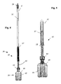
- Fig. 2 shows another embodiment of a wiper device 31 for a device 1 according to the invention for drying.
- the wiper device 31 has a mop head 29 designed as a mop, which is equipped with a plurality of fringes 43.
- the fringes 43 are arranged on a disc-shaped holder 49.
- the wiper device 31 has a handle 51, which carries the spindle 53 of a spindle drive 55.
- the spindle drive 55 comprises a relative to the stem 51 rotatably mounted spindle nut 57, which cooperates with the spindle 53 for generating a rotational movement.
- the user holds the wiper device 31 with one hand on a handle 59, which is rotatably mounted on the mop head 29 opposite end of the handle 51, fixed and moved with the other hand, the spindle nut 57 along the longitudinal extent of the handle 51 up and down , so that the handle 51 is rotated together with the mop head 29 in rotation.
- It is an unillustrated freewheel that allows free rotation of the stem 51 relative to the spindle nut 57 in a rotational direction, so that the stem 51 with the mop head 29 undergoes a driving force when the Spindle nut 57 is moved in one direction, while in the movement of the spindle nut 57 in the other direction no forces on the stem 51 and the mop head 29 are transmitted.
- the wiper device 31 has a further handle 61 which can be used during wiping.
- the fringes 43 are made of strips of non-woven fabric, but they may also be formed of fibers, yarns or the like. It is also possible for the wiper device 31 to be equipped with a flat wiper instead of a mop as a mopping head 29, for example with folding wiper plates.
- Fig. 3 shows the spindle drive 55 of in Fig. 2 illustrated wiper device 31 in detail.
- the thread of the spindle 53 is equipped as a multi-movement thread with a very high pitch, preferably in the range of 0.5 cm to 10 cm per revolution, in particular 1 cm to 2 cm per revolution, so that by the linear movement of the spindle nut 57, the speed of the spindle 53 and thus of the mop head 29 is correspondingly high in order to eject dirt particles and moisture out of the mop head 29.
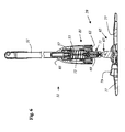
- Fig. 4 shows a further embodiment of a wiper device 31 for a device 1 according to the invention for drying.
- This wiper device 31 also has a drive device 39 designed as a spindle drive 55.
- the wiper head 29 is rotatably mounted on a spindle 53, while on the stem 51 - coaxial with this - rotatably a spindle nut 57 is arranged.
- a rotary sleeve 63 is rotatably mounted relative to the spindle 53 about its longitudinal axis.
- the wiper device 31 For ejecting the wiper head 29, the wiper device 31 is suspended in a device for drying 1 in such a way that the rotary sleeve 63 of the wiper device 31 rests on a support - for example a part of an insertion shaft - supporting the wiper device.
- the wiper head 29 is thereby rotatably suspended relative to the rotary sleeve 63 and thus relative to the support 87 and, for example, in a - preferably a rotatable sieve having - projecting container.
- the spindle 53 By depressing the stem 51 toward the rotary sleeve 63, the spindle 53 rotatably moves into the spindle nut 57, so that the mop head 29 connected to the spindle 53 is rotated.
- the spindle drive 55 has a freewheel, not shown, which allows largely without force on the Wiper head 29 the stem 51 together with the spindle nut 57 - preferably with spring force - in the opposite direction - ie away from the rotary sleeve 63 - to move. Subsequently, the wiper head 29 can be further accelerated by cyclic repetition of this process.
- Fig. 5 shows the spindle drive 55 of in Fig. 4 illustrated wiper device 31 in detail.
- Fig. 6 shows a further embodiment of a wiper device 31 for a device according to the invention for drying 1.
- the wiper device 31 has a handle 51, on which a spindle nut 57 is arranged rotationally fixed.
- the wiping head 29, which is designed as a flat wiping head 65, is connected to a spindle 53 via a universal joint 67, which allows a more comfortable wiping.
- a screw connection 71 is provided between the spindle mount 69 and the mop head 29.
- a rotary sleeve 63 is rotatably mounted relative to the spindle 53 about its longitudinal axis. Analogous to the respect Fig.
- the wiper head 29 can be set by moving the handle 51 in the direction of the rotary sleeve 63 in rotation.
- the spring 73 is compressed, which pushes the handle 51 together with the spindle nut 57 back into the starting position as soon as the user allows this movement after the spin head 29 has been rotationally accelerated.
- a freewheel not shown, which allows independent of the rotational movement of the stem 51 to the starting position is provided.
- the mop head 29 has a hinged wiper plate 75 with two plate wings 77. In the working position shown, the plate wings 77 are in a common plane and tension a attached to them - not shown - mop cover. With a release device 79 - a foot pedal in this embodiment - the lock can be solved, whereby the plate wings 77 and mop cover hang down freely to perform a Ausschleudervorganges.
- the locking device 81 has a relative to the longitudinal extent of the handle 51 slidably mounted bell 83, which is provided at its lower edge with locking lugs.
- the bell 83 is rotationally fixed and arranged coaxially with the stem 51. The detents engage in the locking position in recesses of the spindle attachment 69 and thereby connect the mop head 29 and the handle 51 rotatably.
- the bell 83 is held in the locked position by the weight force.
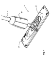
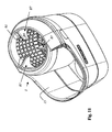
- Fig. 7 shows in a section the end of the in Fig. 2 illustrated wiper device 31 in a perspective view.
- Fig. 8 shows the - particularly compact - spindle drive 55 of another wiper device 31 in an exploded view.
- the recess 85 of the spindle attachment 69 in which engages the - not to be seen - latching nose of the bell 83 in the wiping position.
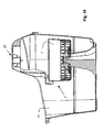
- Fig. 9 shows a device according to the invention for drying 1 a mop head 29.
- the device 1 has a container 15 which carries a spinner 3.
- the centrifugal device 3 has a support 87 into which a wiper device 29 can be suspended in the drying device 1 for ejecting a wiper head 29 in such a way that the rotary sleeve 63 of the wiper device 31 supports the wiper device 31 on a support 87 - for example a part of an insertion shaft rests and the wiper head 29 thereby rotatable relative to the rotary sleeve 63 and thus relative to the support 87 is suspended.
- the wiper head 29 protrudes here into a receptacle 5, which is designed as a rotatably mounted sieve.
- the support 87 has a first support step 89 for the rotary sleeve 63 of a wiper device 31 (see, for example 4, 5 and 6 ) and a second support step 91 for the bell 83 of a wiper device 31 (see, eg 4, 5 and 6 ) on.
- the bell 83 comes to lie on the second support step 91 and is thereby moved relative to the handle up and repealed the handle-mopping rotary locking.
- the bell 83 falls down and restores the twist lock.
- Fig. 10 shows the already in Fig. 9 illustrated device for drying 1 in a sectional view.
- the screen 7 is rotatably mounted on a mandrel and is driven in rotation by the rotating mop head of the mop.
- the sieve 7 is driven directly by a drive device.
- the illustrated apparatus for drying 1 is particularly well suited for drying flat wipers provided with a mop cover, in particular with folding mop wings.
- Fig. 11 shows another device for drying 1 a mop head 29, a three-arm bearing 87 each having a first support step 89 for the rotary sleeve 63 of a wiper device 31 (see, eg 4, 5 and 6 ) and a second support step 91 for the bell 83 of a wiper device 31 (see, eg 4, 5 and 6 ) having.
- the illustrated device for drying 1 is particularly suitable for drying wiping heads 29 in the form of a mop - for example a strip wiping mop.
Landscapes
- Cleaning Implements For Floors, Carpets, Furniture, Walls, And The Like (AREA)
- Drying Of Solid Materials (AREA)
- Formation Of Various Coating Films On Cathode Ray Tubes And Lamps (AREA)
Applications Claiming Priority (3)
| Application Number | Priority Date | Filing Date | Title |
|---|---|---|---|
| DE102005019624.1A DE102005019624B4 (de) | 2005-04-26 | 2005-04-26 | Feuchtreinigungsgerät |
| DE200510023084 DE102005023084A1 (de) | 2005-05-13 | 2005-05-13 | Vorrichtung zum Trocknen eines Wischmops |
| PCT/EP2006/003740 WO2006114253A1 (de) | 2005-04-26 | 2006-04-24 | Vorrichtung zum trockenschleudern eines wischkopfes |
Publications (2)
| Publication Number | Publication Date |
|---|---|
| EP1890583A1 EP1890583A1 (de) | 2008-02-27 |
| EP1890583B1 true EP1890583B1 (de) | 2012-12-12 |
Family
ID=36587069
Family Applications (4)
| Application Number | Title | Priority Date | Filing Date |
|---|---|---|---|
| EP06724523A Expired - Lifetime EP1890583B1 (de) | 2005-04-26 | 2006-04-24 | Vorrichtung zum trockenschleudern eines wischkopfes |
| EP06742652A Expired - Lifetime EP1890585B1 (de) | 2005-04-26 | 2006-04-24 | Wischgerät und vorrichtung zum trocknen mit einer antriebsvorrichtung zum trockenschleudern eines wischkopfes sowie reinigungssystem hieraus |
| EP06724524A Expired - Lifetime EP1890584B1 (de) | 2005-04-26 | 2006-04-24 | Vorrichtung zum trockenschleudern eines wischkopfes |
| EP06724522A Expired - Lifetime EP1898770B1 (de) | 2005-04-26 | 2006-04-24 | Wischgerät mit drehantrieb |
Family Applications After (3)
| Application Number | Title | Priority Date | Filing Date |
|---|---|---|---|
| EP06742652A Expired - Lifetime EP1890585B1 (de) | 2005-04-26 | 2006-04-24 | Wischgerät und vorrichtung zum trocknen mit einer antriebsvorrichtung zum trockenschleudern eines wischkopfes sowie reinigungssystem hieraus |
| EP06724524A Expired - Lifetime EP1890584B1 (de) | 2005-04-26 | 2006-04-24 | Vorrichtung zum trockenschleudern eines wischkopfes |
| EP06724522A Expired - Lifetime EP1898770B1 (de) | 2005-04-26 | 2006-04-24 | Wischgerät mit drehantrieb |
Country Status (10)
| Country | Link |
|---|---|
| US (1) | US8544133B2 (pl) |
| EP (4) | EP1890583B1 (pl) |
| AT (1) | ATE545358T1 (pl) |
| DE (3) | DE202006020930U1 (pl) |
| DK (1) | DK1890585T3 (pl) |
| ES (1) | ES2381027T3 (pl) |
| PL (1) | PL1890585T3 (pl) |
| PT (1) | PT1890585E (pl) |
| SI (1) | SI1890585T1 (pl) |
| WO (4) | WO2006114254A1 (pl) |
Cited By (2)
| Publication number | Priority date | Publication date | Assignee | Title |
|---|---|---|---|---|
| USD723234S1 (en) | 2014-05-20 | 2015-02-24 | Telebrands Corp. | Dual spout mop bucket with agitator |
| USD723758S1 (en) | 2014-05-20 | 2015-03-03 | Telebrands, Corp. | Dual spout mop bucket |
Families Citing this family (40)
| Publication number | Priority date | Publication date | Assignee | Title |
|---|---|---|---|---|
| DE102007005973A1 (de) | 2007-02-07 | 2008-08-14 | Leifheit Ag | Wischer |
| DE102009016205B4 (de) * | 2009-04-03 | 2011-06-22 | Leifheit AG, 56377 | Als Zerkleinerungsvorrichtung für Lebensmittel, Rührvorrichtung oder Schleudervorrichtung ausgebildete Vorrichtung |
| DE102009016204B4 (de) | 2009-04-03 | 2011-05-26 | Leifheit Ag | Spindelantriebsvorrichtung |
| CN101579223B (zh) * | 2009-05-11 | 2011-01-05 | 董成勇 | 一种手压旋转脱水桶 |
| KR200458286Y1 (ko) | 2009-05-27 | 2012-01-31 | 투오 쉔 인터내셔널 코퍼레이션 리미티드 | 논-스테핑 탈수 버킷 |
| TWM368421U (en) * | 2009-05-27 | 2009-11-11 | Tuo Dih Shen Internat Corp | Step-free dehydration bucket |
| KR100989357B1 (ko) | 2009-12-30 | 2010-10-26 | 김기원 | 봉 걸레 탈수조립체 |
| TWM386045U (en) * | 2010-03-16 | 2010-08-11 | cong-mou You | Spinning mop |
| DE102010016322B3 (de) * | 2010-04-01 | 2011-07-21 | Leifheit AG, 56377 | Antriebsvorrichtung für eine Zerkleinerungs- und/oder Schleudervorrichtung, Zerkleinerungsvorrichtung und Schleudervorrichtung |
| WO2011137730A1 (zh) * | 2010-05-04 | 2011-11-10 | Zhao Yimei | 拖把桶和拖把及拖把清洗方法 |
| CN101904728A (zh) * | 2010-07-08 | 2010-12-08 | 赵一美 | 拖把清洗方法 |
| CN104939775B (zh) * | 2010-05-31 | 2019-05-17 | 王鹏 | 清洁工具 |
| KR200451004Y1 (ko) | 2010-08-09 | 2010-11-16 | 윤홍찬 | 청소용구 |
| KR200464298Y1 (ko) | 2010-10-08 | 2012-12-24 | 주식회사 삼성웰비스 | 세척기능을 갖는 탈수장치 |
| CN201831828U (zh) * | 2010-10-20 | 2011-05-18 | 游聪谋 | 自转拖把 |
| CN103188984B (zh) * | 2010-11-04 | 2016-05-04 | 3M创新有限公司 | 拖把 |
| DE202011052363U1 (de) * | 2010-12-30 | 2012-01-24 | Rock Tone Enterprise Co., Ltd. | Wischmoppset |
| ES2463391T3 (es) | 2011-07-15 | 2014-05-27 | Leifheit Ag | Placa limpiadora para un limpiador de suelo |
| PT2545837E (pt) | 2011-07-15 | 2014-01-30 | Leifheit Ag | Sistema de limpeza com cesto de centrifugação |
| CN202875265U (zh) * | 2012-10-11 | 2013-04-17 | 3M中国有限公司 | 可折叠旋转平板拖把和包括它的清洁工具组件 |
| US8997305B1 (en) | 2014-04-28 | 2015-04-07 | Telebrands Corp. | Rotating mop handle and bucket assembly |
| USD720905S1 (en) | 2014-04-30 | 2015-01-06 | Telebrands Corp. | Base for a cleaning apparatus |
| DE202014008140U1 (de) | 2014-10-14 | 2016-01-18 | Ds Produkte Gmbh | Wischgerät |
| FR3040282B1 (fr) * | 2015-08-26 | 2017-08-11 | Regis Masquin | Balai a laver a semelle pliable et ensemble de lavage comprenant le balai. |
| DE102015116169B3 (de) * | 2015-09-24 | 2017-01-26 | Ds Produkte Gmbh | Reinigungssystem, Wischgerät, Behälter und Verfahren zum Reinigen und zum Nachrüsten von Reinigungsmitteln |
| CN107456176B (zh) * | 2016-06-03 | 2022-06-17 | 孙振东 | 清洗时可变速的清洁工具 |
| TR201613645U (tr) * | 2016-08-25 | 2018-03-21 | Freudenberg Carl Kg | Paspas ci̇hazi. |
| AU201811258S (en) | 2017-09-06 | 2018-05-23 | Freudenberg Carl Kg | Mop handle |
| CN108175346B (zh) * | 2018-02-12 | 2023-10-31 | 河北洁仕宝日用塑料制品有限公司 | 立刮折甩清洁工具 |
| CN209136491U (zh) * | 2018-04-11 | 2019-07-23 | 江苏宙际杰智能科技股份有限公司 | 净污水分离的拖把清洗装置 |
| DE102020117838B4 (de) | 2020-07-07 | 2022-04-21 | Leifheit Aktiengesellschaft | Eimer mit Entfeuchtungseinsatz zum Auspressen eines Wischkopfes |
| USD903211S1 (en) * | 2020-07-23 | 2020-11-24 | Hongtao Gao | Dog pooper scooper rod |
| CH717852A1 (de) * | 2020-09-15 | 2022-03-15 | Eyco Direkt Anstalt | Auswringvorrichtung für ein Wischgerät und Auswringsystem mit einer Auswringvorrichtung und einem Eimer. |
| USD973294S1 (en) | 2021-04-20 | 2022-12-20 | The Libman Company | Mop |
| US11717130B2 (en) | 2021-04-20 | 2023-08-08 | The Libman Company | Mop system with rotating mop head |
| USD973295S1 (en) | 2021-04-20 | 2022-12-20 | The Libman Company | Bucket |
| CN113143139B (zh) * | 2021-04-27 | 2024-04-12 | 金卫良 | 一种自拧拖把 |
| FR3127108B1 (fr) | 2021-09-23 | 2023-09-15 | Seb Sa | Dispositif d’entrainement à rotation unidirectionnelle ou bidirectionnelle |
| DE202022105445U1 (de) | 2022-06-07 | 2022-10-06 | Ds Produkte Gmbh | Spinnmopp |
| US12245732B2 (en) | 2023-05-03 | 2025-03-11 | The Libman Company | Grip handle assembly for a mop |
Family Cites Families (22)
| Publication number | Priority date | Publication date | Assignee | Title |
|---|---|---|---|---|
| GB235684A (en) * | 1924-04-17 | 1925-06-25 | Gerald Lawrenoe Opperman | Improvements in and relating to mops |
| US1818948A (en) | 1928-09-10 | 1931-08-11 | Harold V Atwell | Mop-shaking device |
| DE583311C (de) | 1932-04-09 | 1933-09-01 | Friedrich Emil Krauss | Kleinschleuder |
| US2777144A (en) | 1955-03-30 | 1957-01-15 | Leslie J Gombar | Rotatable head dust mop |
| US3197794A (en) | 1963-07-22 | 1965-08-03 | Fallek Joseph | Dust mop cleaner |
| DE1628858A1 (de) | 1967-10-09 | 1971-07-01 | Herbert Zoels | Fussboden-Nassreiniger mit Fliehkraft-Wasserausschleuderung |
| US4506403A (en) * | 1980-12-03 | 1985-03-26 | Trisolini George S | Cleaning apparatus |
| US4344201A (en) * | 1980-12-03 | 1982-08-17 | Trisolini George S | Cleaning apparatus |
| EP0162815A1 (en) * | 1984-04-17 | 1985-11-27 | Giorgio Trisolini | Improved floor-washing apparatus provided with a self-wringing device |
| FR2672791B1 (fr) | 1991-02-14 | 1994-12-23 | Maxnet | Dispositif d'essorage pour tete de balai. |
| US5361448A (en) * | 1993-05-10 | 1994-11-08 | Chao Shu H A | Dewatering device for a swab |
| US5722105A (en) | 1995-12-28 | 1998-03-03 | Thomasson; Stig Ola | Floor mop and wringing mechanism therefor |
| FR2769204B1 (fr) | 1997-10-06 | 1999-11-26 | Net System | Dispositif d'essorage pour tete de balai |
| TW389684B (en) * | 1998-08-20 | 2000-05-11 | Luo De Liang | Portable electric cleaning device |
| JP2000350691A (ja) | 1999-06-11 | 2000-12-19 | Susumu Iwasaki | モップ脱水機 |
| DE10223074C1 (de) | 2002-05-24 | 2003-08-14 | Kaercher Gmbh & Co Kg Alfred | Vorrichtung zum Ausschleudern von Flüssigkeit aus einem Wischkörper |
| DE10311799B3 (de) | 2003-03-12 | 2004-07-08 | Alfred Kärcher Gmbh & Co. Kg | Vorrichtung zum Auswaschen und Ausschleudern eines Wischkörpers |
| DE10311812B3 (de) | 2003-03-12 | 2004-07-01 | Alfred Kärcher GmbH & Co KG | Vorrichtung zum Auswaschen und Ausschleudern eines Wischkörpers |
| DE10343324A1 (de) | 2003-09-11 | 2005-04-14 | Alfred Kärcher Gmbh & Co. Kg | Vorrichtung zum Ausschleudern einer Wischbespannung |
| US20110000046A1 (en) * | 2009-07-01 | 2011-01-06 | Chen Yung-Hua | Non-stepping wringer bucket |
| US8291544B2 (en) * | 2009-07-01 | 2012-10-23 | Tuo Shen International Corporation Limited | Mop with the function of dewatering the yarns by twisting in a single direction via an up-and-down linear motion |
| US8220101B2 (en) * | 2009-12-29 | 2012-07-17 | Tuo Shen International Corporation Limited | Telescopically rotatable mop |
-
2006
- 2006-04-24 EP EP06724523A patent/EP1890583B1/de not_active Expired - Lifetime
- 2006-04-24 PT PT06742652T patent/PT1890585E/pt unknown
- 2006-04-24 EP EP06742652A patent/EP1890585B1/de not_active Expired - Lifetime
- 2006-04-24 PL PL06742652T patent/PL1890585T3/pl unknown
- 2006-04-24 WO PCT/EP2006/003741 patent/WO2006114254A1/de not_active Ceased
- 2006-04-24 DK DK06742652.8T patent/DK1890585T3/da active
- 2006-04-24 US US12/279,827 patent/US8544133B2/en active Active
- 2006-04-24 DE DE202006020930U patent/DE202006020930U1/de not_active Expired - Lifetime
- 2006-04-24 WO PCT/EP2006/003738 patent/WO2006114251A1/de not_active Ceased
- 2006-04-24 AT AT06742652T patent/ATE545358T1/de active
- 2006-04-24 ES ES06742652T patent/ES2381027T3/es not_active Expired - Lifetime
- 2006-04-24 EP EP06724524A patent/EP1890584B1/de not_active Expired - Lifetime
- 2006-04-24 DE DE202006020883U patent/DE202006020883U1/de not_active Expired - Lifetime
- 2006-04-24 SI SI200631310T patent/SI1890585T1/sl unknown
- 2006-04-24 EP EP06724522A patent/EP1898770B1/de not_active Expired - Lifetime
- 2006-04-24 WO PCT/EP2006/003740 patent/WO2006114253A1/de not_active Ceased
- 2006-04-24 WO PCT/EP2006/003739 patent/WO2006114252A1/de not_active Ceased
- 2006-04-24 DE DE202006021005U patent/DE202006021005U1/de not_active Expired - Lifetime
Cited By (2)
| Publication number | Priority date | Publication date | Assignee | Title |
|---|---|---|---|---|
| USD723234S1 (en) | 2014-05-20 | 2015-02-24 | Telebrands Corp. | Dual spout mop bucket with agitator |
| USD723758S1 (en) | 2014-05-20 | 2015-03-03 | Telebrands, Corp. | Dual spout mop bucket |
Also Published As
| Publication number | Publication date |
|---|---|
| EP1890583A1 (de) | 2008-02-27 |
| WO2006114253A1 (de) | 2006-11-02 |
| DE202006020930U1 (de) | 2010-12-30 |
| PL1890585T3 (pl) | 2012-06-29 |
| WO2006114252A1 (de) | 2006-11-02 |
| ES2381027T3 (es) | 2012-05-22 |
| SI1890585T1 (sl) | 2012-05-31 |
| DE202006021005U1 (de) | 2012-01-23 |
| EP1890584B1 (de) | 2012-12-12 |
| DE202006020883U1 (de) | 2010-08-12 |
| DK1890585T3 (da) | 2012-05-07 |
| ATE545358T1 (de) | 2012-03-15 |
| US20090307856A1 (en) | 2009-12-17 |
| EP1890584A1 (de) | 2008-02-27 |
| EP1890585B1 (de) | 2012-02-15 |
| EP1898770A1 (de) | 2008-03-19 |
| PT1890585E (pt) | 2012-05-25 |
| WO2006114251A1 (de) | 2006-11-02 |
| EP1890585A1 (de) | 2008-02-27 |
| EP1898770B1 (de) | 2012-12-12 |
| US8544133B2 (en) | 2013-10-01 |
| WO2006114254A1 (de) | 2006-11-02 |
Similar Documents
| Publication | Publication Date | Title |
|---|---|---|
| EP1890583B1 (de) | Vorrichtung zum trockenschleudern eines wischkopfes | |
| EP3426122B1 (de) | Flächen-reinigungsmaschine | |
| DE10223074C1 (de) | Vorrichtung zum Ausschleudern von Flüssigkeit aus einem Wischkörper | |
| EP3426121B1 (de) | Flächen-reinigungsmaschine | |
| EP4193898B1 (de) | Bodenreinigungsmaschine mit abscheidereinrichtung | |
| DE1628724A1 (de) | Staubsauger,insbesondere zum Reinigen von Teppichen od.dgl. | |
| DE102024103698A1 (de) | Flächenreinigungsgerät mit Fixierungseinrichtung und Verfahren zur Entnahme einer Kassette | |
| EP2545837B1 (de) | Reinigungssystem mit Schleuderkorb | |
| DE4426079A1 (de) | Gerät zur Reinigung von Walzen | |
| EP1955639B1 (de) | Reinigungssystem | |
| DE10343324A1 (de) | Vorrichtung zum Ausschleudern einer Wischbespannung | |
| DE102005023084A1 (de) | Vorrichtung zum Trocknen eines Wischmops | |
| DE102005019624B4 (de) | Feuchtreinigungsgerät | |
| DE102015116169B3 (de) | Reinigungssystem, Wischgerät, Behälter und Verfahren zum Reinigen und zum Nachrüsten von Reinigungsmitteln | |
| WO2004080268A1 (de) | Vorrichtung zum ausschleudern eines wischkörpers | |
| EP4195991B1 (de) | Reinigungsgerät | |
| DE202016008945U1 (de) | Flächen-Reinigungsmaschine | |
| DE202022105445U1 (de) | Spinnmopp | |
| DE1628763C (de) | Reinigungsgerät zur Feuchtreinigung von Bodenflachen | |
| WO2023148006A1 (de) | Reinigungsgerät zur bodenreinigung mit reinigungsrolle | |
| DE202011108402U1 (de) | Aufnahme für ein Reinigungsgerät | |
| DE102017100368A1 (de) | Eigenständige Regenerationseinheit zur Regeneration eines Reinigungselementes |
Legal Events
| Date | Code | Title | Description |
|---|---|---|---|
| PUAI | Public reference made under article 153(3) epc to a published international application that has entered the european phase |
Free format text: ORIGINAL CODE: 0009012 |
|
| 17P | Request for examination filed |
Effective date: 20071126 |
|
| AK | Designated contracting states |
Kind code of ref document: A1 Designated state(s): AT BE BG CH CY CZ DE DK EE ES FI FR GB GR HU IE IS IT LI LT LU LV MC NL PL PT RO SE SI SK TR |
|
| DAX | Request for extension of the european patent (deleted) | ||
| 17Q | First examination report despatched |
Effective date: 20090423 |
|
| GRAP | Despatch of communication of intention to grant a patent |
Free format text: ORIGINAL CODE: EPIDOSNIGR1 |
|
| GRAS | Grant fee paid |
Free format text: ORIGINAL CODE: EPIDOSNIGR3 |
|
| GRAA | (expected) grant |
Free format text: ORIGINAL CODE: 0009210 |
|
| AK | Designated contracting states |
Kind code of ref document: B1 Designated state(s): AT BE BG CH CY CZ DE DK EE ES FI FR GB GR HU IE IS IT LI LT LU LV MC NL PL PT RO SE SI SK TR |
|
| REG | Reference to a national code |
Ref country code: GB Ref legal event code: FG4D Free format text: NOT ENGLISH |
|
| REG | Reference to a national code |
Ref country code: CH Ref legal event code: EP |
|
| REG | Reference to a national code |
Ref country code: AT Ref legal event code: REF Ref document number: 587934 Country of ref document: AT Kind code of ref document: T Effective date: 20121215 |
|
| REG | Reference to a national code |
Ref country code: IE Ref legal event code: FG4D Free format text: LANGUAGE OF EP DOCUMENT: GERMAN |
|
| REG | Reference to a national code |
Ref country code: DE Ref legal event code: R096 Ref document number: 502006012306 Country of ref document: DE Effective date: 20130207 |
|
| REG | Reference to a national code |
Ref country code: NL Ref legal event code: T3 |
|
| PG25 | Lapsed in a contracting state [announced via postgrant information from national office to epo] |
Ref country code: SE Free format text: LAPSE BECAUSE OF FAILURE TO SUBMIT A TRANSLATION OF THE DESCRIPTION OR TO PAY THE FEE WITHIN THE PRESCRIBED TIME-LIMIT Effective date: 20121212 Ref country code: FI Free format text: LAPSE BECAUSE OF FAILURE TO SUBMIT A TRANSLATION OF THE DESCRIPTION OR TO PAY THE FEE WITHIN THE PRESCRIBED TIME-LIMIT Effective date: 20121212 Ref country code: ES Free format text: LAPSE BECAUSE OF FAILURE TO SUBMIT A TRANSLATION OF THE DESCRIPTION OR TO PAY THE FEE WITHIN THE PRESCRIBED TIME-LIMIT Effective date: 20130323 Ref country code: LT Free format text: LAPSE BECAUSE OF FAILURE TO SUBMIT A TRANSLATION OF THE DESCRIPTION OR TO PAY THE FEE WITHIN THE PRESCRIBED TIME-LIMIT Effective date: 20121212 |
|
| REG | Reference to a national code |
Ref country code: LT Ref legal event code: MG4D |
|
| PG25 | Lapsed in a contracting state [announced via postgrant information from national office to epo] |
Ref country code: LV Free format text: LAPSE BECAUSE OF FAILURE TO SUBMIT A TRANSLATION OF THE DESCRIPTION OR TO PAY THE FEE WITHIN THE PRESCRIBED TIME-LIMIT Effective date: 20121212 Ref country code: SI Free format text: LAPSE BECAUSE OF FAILURE TO SUBMIT A TRANSLATION OF THE DESCRIPTION OR TO PAY THE FEE WITHIN THE PRESCRIBED TIME-LIMIT Effective date: 20121212 Ref country code: GR Free format text: LAPSE BECAUSE OF FAILURE TO SUBMIT A TRANSLATION OF THE DESCRIPTION OR TO PAY THE FEE WITHIN THE PRESCRIBED TIME-LIMIT Effective date: 20130313 |
|
| PG25 | Lapsed in a contracting state [announced via postgrant information from national office to epo] |
Ref country code: CY Free format text: LAPSE BECAUSE OF FAILURE TO SUBMIT A TRANSLATION OF THE DESCRIPTION OR TO PAY THE FEE WITHIN THE PRESCRIBED TIME-LIMIT Effective date: 20121212 Ref country code: EE Free format text: LAPSE BECAUSE OF FAILURE TO SUBMIT A TRANSLATION OF THE DESCRIPTION OR TO PAY THE FEE WITHIN THE PRESCRIBED TIME-LIMIT Effective date: 20121212 Ref country code: IS Free format text: LAPSE BECAUSE OF FAILURE TO SUBMIT A TRANSLATION OF THE DESCRIPTION OR TO PAY THE FEE WITHIN THE PRESCRIBED TIME-LIMIT Effective date: 20130412 Ref country code: SK Free format text: LAPSE BECAUSE OF FAILURE TO SUBMIT A TRANSLATION OF THE DESCRIPTION OR TO PAY THE FEE WITHIN THE PRESCRIBED TIME-LIMIT Effective date: 20121212 Ref country code: BG Free format text: LAPSE BECAUSE OF FAILURE TO SUBMIT A TRANSLATION OF THE DESCRIPTION OR TO PAY THE FEE WITHIN THE PRESCRIBED TIME-LIMIT Effective date: 20130312 |
|
| PG25 | Lapsed in a contracting state [announced via postgrant information from national office to epo] |
Ref country code: PT Free format text: LAPSE BECAUSE OF FAILURE TO SUBMIT A TRANSLATION OF THE DESCRIPTION OR TO PAY THE FEE WITHIN THE PRESCRIBED TIME-LIMIT Effective date: 20130412 Ref country code: PL Free format text: LAPSE BECAUSE OF FAILURE TO SUBMIT A TRANSLATION OF THE DESCRIPTION OR TO PAY THE FEE WITHIN THE PRESCRIBED TIME-LIMIT Effective date: 20121212 Ref country code: RO Free format text: LAPSE BECAUSE OF FAILURE TO SUBMIT A TRANSLATION OF THE DESCRIPTION OR TO PAY THE FEE WITHIN THE PRESCRIBED TIME-LIMIT Effective date: 20121212 |
|
| PLBE | No opposition filed within time limit |
Free format text: ORIGINAL CODE: 0009261 |
|
| STAA | Information on the status of an ep patent application or granted ep patent |
Free format text: STATUS: NO OPPOSITION FILED WITHIN TIME LIMIT |
|
| PG25 | Lapsed in a contracting state [announced via postgrant information from national office to epo] |
Ref country code: DK Free format text: LAPSE BECAUSE OF FAILURE TO SUBMIT A TRANSLATION OF THE DESCRIPTION OR TO PAY THE FEE WITHIN THE PRESCRIBED TIME-LIMIT Effective date: 20121212 |
|
| 26N | No opposition filed |
Effective date: 20130913 |
|
| PG25 | Lapsed in a contracting state [announced via postgrant information from national office to epo] |
Ref country code: MC Free format text: LAPSE BECAUSE OF FAILURE TO SUBMIT A TRANSLATION OF THE DESCRIPTION OR TO PAY THE FEE WITHIN THE PRESCRIBED TIME-LIMIT Effective date: 20121212 |
|
| REG | Reference to a national code |
Ref country code: DE Ref legal event code: R097 Ref document number: 502006012306 Country of ref document: DE Effective date: 20130913 |
|
| REG | Reference to a national code |
Ref country code: IE Ref legal event code: MM4A |
|
| PG25 | Lapsed in a contracting state [announced via postgrant information from national office to epo] |
Ref country code: IE Free format text: LAPSE BECAUSE OF NON-PAYMENT OF DUE FEES Effective date: 20130424 |
|
| PG25 | Lapsed in a contracting state [announced via postgrant information from national office to epo] |
Ref country code: TR Free format text: LAPSE BECAUSE OF FAILURE TO SUBMIT A TRANSLATION OF THE DESCRIPTION OR TO PAY THE FEE WITHIN THE PRESCRIBED TIME-LIMIT Effective date: 20121212 |
|
| PG25 | Lapsed in a contracting state [announced via postgrant information from national office to epo] |
Ref country code: HU Free format text: LAPSE BECAUSE OF FAILURE TO SUBMIT A TRANSLATION OF THE DESCRIPTION OR TO PAY THE FEE WITHIN THE PRESCRIBED TIME-LIMIT; INVALID AB INITIO Effective date: 20060424 Ref country code: LU Free format text: LAPSE BECAUSE OF NON-PAYMENT OF DUE FEES Effective date: 20130424 |
|
| REG | Reference to a national code |
Ref country code: DE Ref legal event code: R008 Ref document number: 502006012306 Country of ref document: DE Ref country code: DE Ref legal event code: R039 Ref document number: 502006012306 Country of ref document: DE |
|
| REG | Reference to a national code |
Ref country code: FR Ref legal event code: PLFP Year of fee payment: 11 |
|
| REG | Reference to a national code |
Ref country code: FR Ref legal event code: PLFP Year of fee payment: 12 |
|
| REG | Reference to a national code |
Ref country code: FR Ref legal event code: PLFP Year of fee payment: 13 |
|
| REG | Reference to a national code |
Ref country code: DE Ref legal event code: R040 Ref document number: 502006012306 Country of ref document: DE |
|
| P01 | Opt-out of the competence of the unified patent court (upc) registered |
Effective date: 20230512 |
|
| P04 | Withdrawal of opt-out of the competence of the unified patent court (upc) registered |
Effective date: 20231006 |
|
| REG | Reference to a national code |
Ref country code: DE Ref legal event code: R082 Ref document number: 502006012306 Country of ref document: DE Representative=s name: KBN IP PATENTANWAELTE PARTNERSCHAFT MBB, DE |
|
| PGFP | Annual fee paid to national office [announced via postgrant information from national office to epo] |
Ref country code: NL Payment date: 20250319 Year of fee payment: 20 |
|
| PGFP | Annual fee paid to national office [announced via postgrant information from national office to epo] |
Ref country code: BE Payment date: 20250319 Year of fee payment: 20 |
|
| PGFP | Annual fee paid to national office [announced via postgrant information from national office to epo] |
Ref country code: FR Payment date: 20250319 Year of fee payment: 20 Ref country code: CZ Payment date: 20250324 Year of fee payment: 20 |
|
| PGFP | Annual fee paid to national office [announced via postgrant information from national office to epo] |
Ref country code: GB Payment date: 20250313 Year of fee payment: 20 |
|
| PGFP | Annual fee paid to national office [announced via postgrant information from national office to epo] |
Ref country code: DE Payment date: 20250403 Year of fee payment: 20 |
|
| PGFP | Annual fee paid to national office [announced via postgrant information from national office to epo] |
Ref country code: IT Payment date: 20250414 Year of fee payment: 20 |
|
| PGFP | Annual fee paid to national office [announced via postgrant information from national office to epo] |
Ref country code: CH Payment date: 20250501 Year of fee payment: 20 |
|
| PGFP | Annual fee paid to national office [announced via postgrant information from national office to epo] |
Ref country code: AT Payment date: 20250326 Year of fee payment: 20 |