EP1890117A1 - Method and apparatus for gas flow measurement - Google Patents
Method and apparatus for gas flow measurement Download PDFInfo
- Publication number
- EP1890117A1 EP1890117A1 EP20070015987 EP07015987A EP1890117A1 EP 1890117 A1 EP1890117 A1 EP 1890117A1 EP 20070015987 EP20070015987 EP 20070015987 EP 07015987 A EP07015987 A EP 07015987A EP 1890117 A1 EP1890117 A1 EP 1890117A1
- Authority
- EP
- European Patent Office
- Prior art keywords
- gas
- flow
- sensing circuit
- calibrated volume
- rate
- Prior art date
- Legal status (The legal status is an assumption and is not a legal conclusion. Google has not performed a legal analysis and makes no representation as to the accuracy of the status listed.)
- Withdrawn
Links
Images


Classifications
-
- G—PHYSICS
- G01—MEASURING; TESTING
- G01F—MEASURING VOLUME, VOLUME FLOW, MASS FLOW OR LIQUID LEVEL; METERING BY VOLUME
- G01F1/00—Measuring the volume flow or mass flow of fluid or fluent solid material wherein the fluid passes through a meter in a continuous flow
- G01F1/05—Measuring the volume flow or mass flow of fluid or fluent solid material wherein the fluid passes through a meter in a continuous flow by using mechanical effects
- G01F1/34—Measuring the volume flow or mass flow of fluid or fluent solid material wherein the fluid passes through a meter in a continuous flow by using mechanical effects by measuring pressure or differential pressure
- G01F1/36—Measuring the volume flow or mass flow of fluid or fluent solid material wherein the fluid passes through a meter in a continuous flow by using mechanical effects by measuring pressure or differential pressure the pressure or differential pressure being created by the use of flow constriction
- G01F1/40—Details of construction of the flow constriction devices
- G01F1/42—Orifices or nozzles
-
- G—PHYSICS
- G01—MEASURING; TESTING
- G01F—MEASURING VOLUME, VOLUME FLOW, MASS FLOW OR LIQUID LEVEL; METERING BY VOLUME
- G01F25/00—Testing or calibration of apparatus for measuring volume, volume flow or liquid level or for metering by volume
- G01F25/10—Testing or calibration of apparatus for measuring volume, volume flow or liquid level or for metering by volume of flowmeters
- G01F25/15—Testing or calibration of apparatus for measuring volume, volume flow or liquid level or for metering by volume of flowmeters specially adapted for gas meters
-
- G—PHYSICS
- G01—MEASURING; TESTING
- G01F—MEASURING VOLUME, VOLUME FLOW, MASS FLOW OR LIQUID LEVEL; METERING BY VOLUME
- G01F1/00—Measuring the volume flow or mass flow of fluid or fluent solid material wherein the fluid passes through a meter in a continuous flow
-
- G—PHYSICS
- G01—MEASURING; TESTING
- G01F—MEASURING VOLUME, VOLUME FLOW, MASS FLOW OR LIQUID LEVEL; METERING BY VOLUME
- G01F25/00—Testing or calibration of apparatus for measuring volume, volume flow or liquid level or for metering by volume
-
- G—PHYSICS
- G01—MEASURING; TESTING
- G01F—MEASURING VOLUME, VOLUME FLOW, MASS FLOW OR LIQUID LEVEL; METERING BY VOLUME
- G01F25/00—Testing or calibration of apparatus for measuring volume, volume flow or liquid level or for metering by volume
- G01F25/10—Testing or calibration of apparatus for measuring volume, volume flow or liquid level or for metering by volume of flowmeters
- G01F25/17—Testing or calibration of apparatus for measuring volume, volume flow or liquid level or for metering by volume of flowmeters using calibrated reservoirs
-
- H—ELECTRICITY
- H01—ELECTRIC ELEMENTS
- H01L—SEMICONDUCTOR DEVICES NOT COVERED BY CLASS H10
- H01L22/00—Testing or measuring during manufacture or treatment; Reliability measurements, i.e. testing of parts without further processing to modify the parts as such; Structural arrangements therefor
-
- Y—GENERAL TAGGING OF NEW TECHNOLOGICAL DEVELOPMENTS; GENERAL TAGGING OF CROSS-SECTIONAL TECHNOLOGIES SPANNING OVER SEVERAL SECTIONS OF THE IPC; TECHNICAL SUBJECTS COVERED BY FORMER USPC CROSS-REFERENCE ART COLLECTIONS [XRACs] AND DIGESTS
- Y10—TECHNICAL SUBJECTS COVERED BY FORMER USPC
- Y10T—TECHNICAL SUBJECTS COVERED BY FORMER US CLASSIFICATION
- Y10T137/00—Fluid handling
- Y10T137/0318—Processes
- Y10T137/0324—With control of flow by a condition or characteristic of a fluid
- Y10T137/0368—By speed of fluid
-
- Y—GENERAL TAGGING OF NEW TECHNOLOGICAL DEVELOPMENTS; GENERAL TAGGING OF CROSS-SECTIONAL TECHNOLOGIES SPANNING OVER SEVERAL SECTIONS OF THE IPC; TECHNICAL SUBJECTS COVERED BY FORMER USPC CROSS-REFERENCE ART COLLECTIONS [XRACs] AND DIGESTS
- Y10—TECHNICAL SUBJECTS COVERED BY FORMER USPC
- Y10T—TECHNICAL SUBJECTS COVERED BY FORMER US CLASSIFICATION
- Y10T137/00—Fluid handling
- Y10T137/7722—Line condition change responsive valves
- Y10T137/7758—Pilot or servo controlled
- Y10T137/7761—Electrically actuated valve
Definitions
- Embodiments of the present invention generally relate to a method and apparatus for measuring gas flow. More specifically, embodiments of the invention generally relate to a method and apparatus for measuring gas flows that are provided to a semiconductor processing chamber and related utilities. In particular, embodiments of the invention generally relate to a method and apparatus for measuring gas flow in a semiconductor processing system, and/or in a processing system having a processing chamber.
- Accurate control of gas flows is an important process control attribute critical to many microelectronic device fabrication processes.
- Providing gas between a substrate and a substrate support in a semiconductor processing chamber is a well-known method for improving heat transfer between the substrate and the substrate support, thereby enhancing the precision of substrate temperature control and uniformity.
- precise control of process gas flows into the processing chamber are required in order to obtain desired processing results, particularly as critical dimensions and film thicknesses shrink.
- gases may be added to processing chamber effluent streams to mitigate the environmental impact of substrate processing. Good control of the gases added to the effluent stream is necessary to ensure both cost effective and proper remediation.
- MFC mass gas flow meter
- a calibration circuit for measuring gas flow may be utilized to verify and/or calibrate gas flows utilized for backside cooling, process gas delivery, purge gas delivery, cleaning agent delivery, carrier gases delivery and remediation gas delivery, among others.
- an apparatus for measuring gas flow in a processing system includes a gas source, a diverter valve, an orifice, a regulating device and a sensing circuit.
- the regulating device is fluidly coupled between the gas source and an inlet of the diverter valve.
- the orifice is fluidly coupled to a first outlet of the diverter valve and has substantially the same flow resistance as a processing chamber.
- the sensing circuit is configured to receive the flow of gases passing through the orifice.
- the sensing circuit utilizes a calibrated volume for receiving the gas flow. From properties and/or attributes measured from the gas in the calibrated volume, the flow rate and/or pressure of the gas entering the sensing circuit may be verified.
- the sensing circuit utilizes a non-calibrated volume for receiving the gas flow. From changes in the properties and/or attributes measured over time of the gas in the non-calibrated volume, the flow rate and/or pressure of the gas entering the sensing circuit may be verified.
- the regulating device may be at least one of a vapor delivery module, a flow divider, a pressure controller, a regulator or a mass flow controller.
- the sensing circuit may include a tank having a calibrated volume.
- the sensing circuit may include vibrating member disposed in the calibrated volume.
- the sensing circuit may include a sensor configured to detect at least one of electrical or magnetic characteristics of gases disposed in the calibrated volume.
- the sensing circuit may include a tank supported by a cantilever.
- a method for measuring gas flow in a semiconductor processing system includes setting a gas flow with a flow control device, flowing the gas from the flow control device through an orifice having substantially the same flow resistance as a processing chamber into a sensing circuit, and comparing a flow determined using the sensing circuit with the setting of the flow control device.
- the method may include sampling a characteristic of a gas present in the sensing circuit until an endpoint is reached. In another embodiment, the method may include sampling until a confidence limit is reached. In another embodiment, the method may include sampling until data converges within a predetermined range. In yet another embodiment, the method may include sampling at a frequency rate of less than about 5 millisecond.
- a method for measuring gas flow in a semiconductor processing system comprises providing a processing system having a gas source coupled to a processing chamber and sensing circuit, the sensing circuit having substantially the same flow resistance as the processing chamber; setting a gas flow with a flow control device, the flow being a flow of process gas provided from the gas source at target rate, the target rate being a predefined rate selected for substrate processing in the processing chamber, the flow exiting the flow control device being at an actual rate; flowing the gas from the flow control device through an orifice having substantially the same flow resistance as a processing chamber into a sensing circuit, thereby flowing the gas at the actual rate into the sensing circuit while bypassing the processing chamber; comparing a flow determined using the sensing circuit with the setting of the flow control device, which includes sensing a metric indicative of the actual flow rate; adjusting the setting of the flow control device to correct differences between the actual rate and the target rate; and flowing the process gas from the flow control device into the processing chamber and processing a substrate therein.
- the invention is also directed to apparatuses for carrying out the disclosed methods and including apparatus parts for performing each described method steps. These method steps may be performed by way of hardware components, a computer programmed by appropriate software, by any combination of the two or in any other manner. Furthermore, the invention is also directed to methods by which the described apparatus operates. It includes method steps for carrying out every function of the apparatus or manufacturing every part of the apparatus.
- Figure 1 is a simplified schematic of a conventional semiconductor processing chamber and gas delivery system having a calibration circuit of the present invention.
- Figures 2-9 are simplified schematics of a calibration circuit having various embodiments of a sensing circuit.
- Figure 1 depicts a simplified schematic of a substrate processing system 100 having one embodiment of a gas delivery system 140 of the present invention coupled to an exemplary a semiconductor processing chamber 120.
- the processing chamber 120 may be configured to perform chemical vapor deposition (CVD), physical vapor deposition (PVD), etch chamber, ion implant, thermal processing, ashing, degassing, orientation or other vacuum processing techniques.
- CVD chemical vapor deposition
- PVD physical vapor deposition
- etch chamber ion implant
- thermal processing ashing
- degassing orientation or other vacuum processing techniques.
- the processing chamber 120 includes a substrate support 124 disposed in a chamber body 122.
- the substrate support 124 generally supports a substrate 126 during processing.
- the substrate support 124 generally includes a passage formed therethrough for delivering a heat transfer gas (hereinafter referred to as backside gas) to an area 118 defined between the substrate 126 and substrate support 124.
- backside gas a heat transfer gas
- the size of the area 118 has been exaggerated in Figure 1 for clarity.
- Examples of common backside gases include helium, nitrogen and argon.
- the chamber body 122 generally includes at least one process gas inlet 128 and a pumping port 134.
- the process gas inlet 128 generally provides process and optionally other gases to the interior volume of the processing chamber 120 to facilitate substrate processing, as is conventionally known.
- the gases entering the chamber body 122 may be distributed across the substrate 126 by a gas distribution plate, or showerhead 130.
- the pumping port 134 is formed in the chamber body 122.
- the pumping port 132 is generally coupled to a pumping system that controls the chamber pressure and removes processing by-products from the interior volume of the chamber body 122.
- the pumping system typically includes one or more vacuum pumps and throttle valves, which are not shown.
- a treatment gas port 144 may be provided to deliver remediation gases into a conduit 160 carrying the effluent stream exiting the chamber body 122 via the pumping port 134.
- gases may be provided to react and/or absorb hazardous reaction by-products, excess process gases or gaseous chamber waste to facilitate removal and/or recovery of certain materials from the effluent stream.
- a purge port 132 may also be provided in the chamber body 122.
- Inert gases may be provided through the purge port 132 into the processing chamber 120 to prevent process gases and/or process by-products from entering certain regions of the chamber 120. Examples of purge gases include nitrogen and helium.
- Gases are generally provided to the inlet port 128, the area 118, the purge port 132 and the treatment gas port 144 from one or more gas delivery circuits.
- Each gas delivery circuit generally includes a mechanism for the precise control of the gases flowing therethrough, and at least one of which, may be configured as the gas delivery system 140 of the present invention.
- one gas delivery system 140 is shown coupled to gas delivery lines 112, 114, 116, 138 respectively routed to the inlet port 128, the area 118, the purge port 132 and the treatment gas port 144.
- each line 112, 114, 116, 138 may be respectively coupled to dedicated, separate circuit gas delivery systems 140.
- the gas delivery system 140 includes a gas source 102, a mass flow meter (MFC) 142, a diverter valve 106 and a calibration circuit 104.
- the diverter valve 106 selectively directs flow from the gas source 102 to the calibration circuit 104 or one of the lines 112, 114, 116, 138 through a conduit 110.
- the MFC 142 is disposed between the gas source 102 and the diverter valve 106.
- the MFC 142 is generally utilized to monitor and control the flow from the gas source 102 into either the calibration circuit 104 or conduit 110 coupling the gas delivery system 140 to the processing chamber 120.
- the calibration circuit 104 is configured to accurately measure gas flow.
- the calibration circuit 104 includes an orifice 108 and a sensing circuit 146.
- the orifice 108 is disposed between the sensing circuit 146 and the diverter valve 106.
- the orifice 108 may be sized such that the restriction maintains a chocked flow condition.
- the size of the orifice is selected to simulate the restriction of the actual processing chamber 120. This creates conditions similar to the MFC 142 flowing into the processing chamber 120 under which to perform flow verifications using the calibration circuit 104, while not requiring flow into the actual processing chamber 120.
- the orifice may be determined by experimentation, empirical analysis or by other suitable method.
- the orifice 108 may be determined by measuring the pressure downstream of the orifice and adjusting the orifice size until a desired pressure is realized.
- the size of the orifice may be selected to be different than the restriction of the actual processing chamber 120, as long as the flow is maintained in a chocked flow condition.
- the orifice 108 is sized to create a critical flow (e.g., chocked flow) condition into the sensing circuit 146.
- Critical flow into the sensing circuit 146 means that the flow is determined by the mass flow rate and aperture size of the orifice 108.
- the flow upstream of the orifice 108 e.g., at the MFC 142 is constant and unaffected by pressure fluctuations, thus the upstream volume need not be considered during flow calculations.
- the orifice 108 may be a fixed or variable restriction. In one embodiment, the orifice 108 may be a machined aperture. In another embodiment, the orifice 108 may be adjustable, such as a needle valve.
- FIG. 2 is a schematic diagram of one embodiment of the sensing circuit 146.
- the sensing circuit 146 generally includes a tank 202 having a vibrating member 204 disposed therein.
- a sensor 206 is interfaced with the vibrating member 204 in a manner suitable for providing a processor 208 with a metric indicative of the frequency of oscillation of the vibrating member 204, which may be correlated to the density of gas within the tank 202.
- the sensor 206 is an accelerometer or other suitable senor.
- the tank 202 has a known or predetermined volume. Gas flowing into sensing circuit 146 through the orifice 108 from the gas source 102 will increase the pressure inside the tank 202, and thus the density of the gas the tank 202. Since the volume of the tank 202 is known, the frequency of the vibrating member 204 may be correlated to the mass of the gas within the tank 202. The change in the frequency of oscillation of the vibrating member 204, given the known tank volume, provides information related to the density change within the tank 202, which is also related to the mass flow rate through the MFC 142. Thus, the frequency of the vibrating member may be utilized to verify and/or calibrate the flow through the MFC 142.
- the volume of the tank 204 may not be known.
- the change in frequency of the oscillating member 204 may be used to verify and/or calibrate the flow rate through the MFC 142.
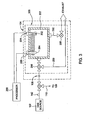
- FIG 3 is a schematic diagram of another embodiment of a sensing circuit 300.
- the sensing circuit 300 generally includes a tank 202 having a vibrating member 204 and a secondary member 302 disposed therein.
- the secondary member 302 is positioned opposite the vibrating member 204.
- a first sensor 206 is interfaced with the vibrating member 204 in a manner suitable for providing a processor 208 with a metric indicative of the frequency of oscillation of the vibrating member 204.
- a second sensor 304 is interfaced with the secondary member 302 in a manner suitable for providing the processor 208 with a metric indicative of the frequency of oscillation of the secondary member 302.
- the vibrating member 204 may be driven at a constant frequency. Energy from the vibrating member 204 is transferred through the gas disposed in the tank 202 and causes the second member 302 to oscillate at a constant frequency. The oscillation of the second member 302 will have a phase shift and amplitude of vibration different than that of the vibrating member 204. These quantities may be measured by the sensors 206, 304 and related to a change in pressure in the tank, which over time relates to a mass flow rate which may be utilized to verify and/or calibrate the flow rate through the MFC 142.
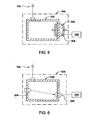
- FIG 4 is a schematic diagram of another embodiment of a sensing circuit 400.
- the sensing circuit 400 generally includes a tank 402 mounted in a cantilevered orientation from a surface 404.
- the mass of gas in the tank 402 is related to the deflection of the cantilevered tank, which may be measured by a sensor 406.
- the sensor 406 may be a strain gauge or a distance measuring device, such as an LVDT. As gas flows into the tank 402, the pressure and density of the gas in the tank 402 will increase, thereby causing a change in the orientation of the tank 402 which is correlated to the additional mass of gas that has been added to the tank 402. The change in tank orientation due to the change in the mass of gas in the tank may be measured by the sensor 406.
- the information from the sensor 406 may be utilized to verify and/or calibrate the MFC 142.
- FIG. 5 is a schematic diagram of another embodiment of a sensing circuit 500.
- the sensing circuit 500 generally includes a tank 502, a displacement device 504 and a sensor 506.
- the tank 502 has a calibrated volume.
- the displacement device 504 may be actuated to disturb the tank 502 such as to cause the tank 502 to oscillate.
- the displacement device 504 may be a transducer, actuator, or other suitable vibration generating device.
- the sensor 506, which may be an accelerometer or other suitable detector, is interfaced with the tank 502 to provide a processor 208 with a metric indicative of the frequency of the tank oscillation. As the mass of gas in the tank 502 increases, the frequency of oscillation will change in a predictable manner which is indicative of a mass flow rate into the tank 502. Thus, the information obtained by the sensor 506 may be utilized to verify the flow rate through the MFC 142.
- the wall of the tank 502 may be perturbed by the displacement device 504 such that it vibrates.
- the stress on the wall will change and the frequency of the vibration will change predictably.
- the vibration may be measured by the sensor 506, and because the volume is known, the pressure change over time may be related to the mass flow rate entering the sensing circuit 500 and may be utilized to verify and/or calibrate the flow rate through the MFC 142.
- FIG. 6 is a schematic diagram of another embodiment of a sensing circuit 600.
- the sensing circuit 600 generally includes a tank 602, a signal generator 604 and a sensor 606.
- the tank 602 has a calibrated volume.
- the signal generator 604 and the sensor 606 may be mounted inside or outside the tank 602.
- the signal generator 604 is configured to generate an acoustic pulse inside the calibrated volume of the tank 602.
- the local speed of the acoustic pulse is related to the density and temperature of the medium (e.g., the gas within the tank).
- the speed of the acoustic pulse may be measured by the sensor 606, and related to the density of the gas within the tank 602.
- the mass of the gas within the tank 602 may be determined using the sensor information and utilized to verify and/or calibrate the flow rate through the MFC 142.
- the signal generator 604 may provide an RF signal or other electromagnetic pulse in the tank 602 to measure the density of gas within the tank. Characteristics of these signals vary predictably with pressure and the sensor 606 may be utilized to provide a metric indicative of at least one of the signal characteristics. The change of the measured characteristics over time may be correlated to a mass flow rate into the sensing circuit 600, and utilized to verify and/or calibrate the flow rate through the MFC 142.
- the senor 606 may be configured to detect changes in at least one of electrical or magnetic characteristics of the gas within the tank 602.
- the electrical or magnetic characteristics change predictably with pressure and may be measured by the sensor 606.
- the metric of change in the electrical or magnetic characteristics of the gas provided by the sensor 606 may be used to determine flow rate through the circuit 600.
- the pressure change over time relates to a mass flow rate in the known volume of the tank 602, and as such, may be utilized to verify and/or calibrate the flow rate through the MFC 142.
- FIG. 7 is a schematic diagram of another embodiment of a sensing circuit 700.
- the sensing circuit 700 generally includes a tank 702 having a piston 704 disposed therein.
- the piston 704 has a known weight and surface area.
- the piston 704 will be displaced against an opposing member 706 relative to the pressure within the tank 702.
- the opposing member 706 may be a spring and/or sealed volume of gas.
- the force needed to move the piston 704 may be resolved from the mass and surface area of the piston 704, the spring force of the opposing member 706, along with the pressure above the piston 704, which can either be controlled or known as a function of piston displacement.
- a sensor 708 is interface with the piston 704 to directly determine the force acting upon the piston.
- the senor 708 may be configured to determine the displacement of the piston 704.
- the force is related to the pressure by the surface area of the piston 704, and the pressure change over time in the known volume may be related to the mass flow rate into the tank 704 and utilized to verify and/or calibrate the flow rate through the MFC 142.
- FIG 8 is a schematic diagram of another embodiment of a sensing circuit 800.
- the sensing circuit 800 generally includes a tank 802 having a piston 704 disposed therein. Flow from the orifice 108 is provided into the tank 802 through first and second inlets 810, 812 respectively positioned above and below the piston 704.
- the piston 704 has known characteristics and will be displaced proportionately to a ratio of flows through the inlets 810, 812. At least one sensor is utilized to determine the relative displacement of the piston 704. In the embodiment depicted in Figure 8, sensors 804, 806 are utilized to determine the displacement of the piston 704 which may be correlated to the flow through the MFC 142.
- FIG. 9 is a schematic diagram of another embodiment of a sensing circuit 900.
- the sensing circuit 900 generally includes a plurality of tanks (shown as tanks 902, 904, 906) coupled to the orifice 108 through a selector valve 908.
- Each tank 902, 904, 906 has a different calibrated volume for use with different ranges of flow rates.
- tank 902 may have a small volume
- tank 904 may have an intermediate volume
- tank 906 may have a large volume.
- the valve 908 is utilized to direct the flow in the circuit 900 to a tank having a volume commensurate flow rate so that good data resolution may be obtained over a reasonable sampling period.
- the smaller tank 902 may be utilized to achieve to achieve greater time resolution for a given pressure rise over a given period of time when low flow rates are being measured.
- the smaller tank 902 facilitate obtaining a rapid pressure rise over time, which provides data set having good resolution over a short sample period.
- the larger tank 908 may be utilized to obtain a pressure rise over time that is not too rapid, thereby providing data having good resolution at high flow rates.
- the larger tank 908 allows the data sample to occur over a longer period of time since the tank holds more volume relative to the small tank 902, which may be filled at high flow rates before a complete data set is obtained. Data relating to the pressure rise may be obtained using any of the techniques described above, or other suitable alternative.
- Each of the sensing circuits described above may include a bypass loop and dump line which allows the tank to be rapidly emptied and refilled, thereby facilitating the rapid acquisition of additional samples.
- Data samples are obtained at a sufficient rate to obtain a statistically valid sample population of data points in a reasonable period of time.
- the frequency rate of sampling is less than about 5 milliseconds. This allows a large data set to be obtained over a shorter test duration, thereby increasing the accuracy of the data while allowing an appropriate endpoint of the test to be rapidly identified.
- the combined measurement error of the sensors/equipment utilized to obtain the data samples may be analyzed to determine their effect on the overall calculation. This information may be utilized to determine and/or adjust the confidence limits.
- the combined measurement error of the sensors/equipment utilized to obtain the data samples may be utilized to simulate a random error distribution in the measured data. A simulated error is then added to each data sample. The number of samples needed to cancel out the effects of the randomly added error may be calculated and utilized as a test end point so that the accurate calculations are realized within the shortest test duration
- An exemplary bypass loop 250 and dump line 252 are shown in the embodiment depicted in Figure 2.
- the flow from the orifice 108 initially goes into the tank 202 and the pressure (density and/or mass) is measured.
- the flow through the sensing circuit 200 is then diverted by a valve 256 through the bypass loop 250 while a second valve 258 is opened to empty the tank 202 through the dump line 252.
- the dump line 252 may be coupled to a vacuum source 260 to expedite the removal of gases from the tank 202.
- the second valve 258 is closed and the flow from the orifice 108 is then directed by the valve 256 back to the tank 202 so that a subsequent sample may be obtained. This process may be repeated multiple times to obtain a data set that provides an accurate measurement of the flow through the MFC 142.
- the processor 208 receiving the date set may use statistical convergence techniques and/or classical robust statistics to determine an appropriate endpoint of the flow verification/calibration. For example, the sampling may be terminated once a suitable convergence calculated based on the known accuracy and repeatability of the measurement devices of the sensing circuit is reached. The sampling endpoint may alternatively be determined dynamically by continuously calculating flows and tracking the convergence toward a mean value.
- the desired level of convergence may be a predetermined level or be determined dynamically using a confidence limit.
- the test will terminate.
- One method of ending the test is to use the known error levels of the measurement devices and use them to calculate the number of samples needed for convergence. Using this predictive method the verification will automatically end once that number of samples has been taken.
- Another method to determine the endpoint is to continuously recalculate the flow and monitor its convergence toward a mean value. As the test runs, every combination of samples collected may be used to calculate the instantaneous flow. When the calculated flows converge to a desired level, the test will terminate.
- the use of multivariate models and statistics to model measurement errors and their effects on the overall system may be used to increase the accuracy of the calculations. The models will show the interaction of different parameters and aid in the selection of optimal parameters.
- Measurement error on both readings will be decreased by averaging multiple samples of each reading, thus making the actual pressure delta for the test more accurate.
- Multivariate models and statistics may be used to model the error of the individual measurements and their effects on the overall system error. These models may be used to determine optimal parameters and system limits. Combinations of the previous techniques may be used to further increase the accuracy of the flow rate calculation.
- flow is determined using standard rate of rise techniques within the tank.
- the orifice at the inlet of the tank is sized to create sonic flow entering the tank.
- the flow into the tank is then related only to the flow from the MFC and the size of the orifice.
- the tank pressure will have no effect on the MFC, and as such, will allow the flow to remain constant.
- the sonic condition at the orifice prevents the upstream pressure from changing, and as such, the mass of gas in the gas line upstream of the orifice remains constant. Under this condition the gas line volume upstream is not utilized in flow calculations, thereby eliminating the need for an upstream volume calculation and further reducing uncertainty in overall flow calculation.
- the MFC can be calibrated under simulated chamber conditions without requiring the actual chamber to be physically present, for example, during bench or pre-installation testing.
- the flow through the MFC may be verified and/or calibrated using the calibration circuit as desired once the chamber is in operation, such as periodic test performed prior to running a new lot of substrates.
- the calibration circuit may be utilized to verify and/or calibrate flow control devices other than MFC's.
- the calibration circuit may be utilized to verify and/or calibrate flow rates (density and/or pressures) from vapor delivery modules, flow dividers, pressure controllers and regulators, among other flow control devices.
- gas delivery systems having calibration circuit that advantageously enable characterization of the MFC utilized to provide gases to a processing system.
- the innovative calibration circuit may be utilized to measure, verify and/or calibrate gas flows utilized for backside cooling, process gas delivery, purge gas delivery, cleaning agent delivery, carrier gases delivery and remediation gas delivery, among others.
- the accuracy and sampling time of the gas flow control has been improved over the state of the art, thereby enabling cost effective and robust processing of next generation devices.
Landscapes
- Physics & Mathematics (AREA)
- Fluid Mechanics (AREA)
- General Physics & Mathematics (AREA)
- Engineering & Computer Science (AREA)
- Manufacturing & Machinery (AREA)
- Computer Hardware Design (AREA)
- Microelectronics & Electronic Packaging (AREA)
- Power Engineering (AREA)
- Measuring Volume Flow (AREA)
- Chemical Vapour Deposition (AREA)
- Drying Of Semiconductors (AREA)
- Physical Vapour Deposition (AREA)
Applications Claiming Priority (2)
| Application Number | Priority Date | Filing Date | Title |
|---|---|---|---|
| US82234506P | 2006-08-14 | 2006-08-14 | |
| US11/833,623 US7743670B2 (en) | 2006-08-14 | 2007-08-03 | Method and apparatus for gas flow measurement |
Publications (1)
| Publication Number | Publication Date |
|---|---|
| EP1890117A1 true EP1890117A1 (en) | 2008-02-20 |
Family
ID=38729030
Family Applications (1)
| Application Number | Title | Priority Date | Filing Date |
|---|---|---|---|
| EP20070015987 Withdrawn EP1890117A1 (en) | 2006-08-14 | 2007-08-14 | Method and apparatus for gas flow measurement |
Country Status (6)
| Country | Link |
|---|---|
| US (2) | US7743670B2 (enExample) |
| EP (1) | EP1890117A1 (enExample) |
| JP (1) | JP2008089575A (enExample) |
| KR (3) | KR20080015374A (enExample) |
| CN (1) | CN101127296B (enExample) |
| TW (1) | TW200820320A (enExample) |
Families Citing this family (31)
| Publication number | Priority date | Publication date | Assignee | Title |
|---|---|---|---|---|
| US7461549B1 (en) * | 2007-06-27 | 2008-12-09 | Mks Instruments, Inc. | Mass flow verifiers capable of providing different volumes, and related methods |
| US7743670B2 (en) * | 2006-08-14 | 2010-06-29 | Applied Materials, Inc. | Method and apparatus for gas flow measurement |
| US8074677B2 (en) * | 2007-02-26 | 2011-12-13 | Applied Materials, Inc. | Method and apparatus for controlling gas flow to a processing chamber |
| US8205629B2 (en) * | 2008-04-25 | 2012-06-26 | Applied Materials, Inc. | Real time lead-line characterization for MFC flow verification |
| EP2113274B1 (en) * | 2008-04-30 | 2016-04-27 | ResMed R&D Germany GmbH | Apparatus for controlled delivery of a breathing gas to the respiratory tracts of a user |
| EP3597251B1 (en) | 2008-06-05 | 2023-04-26 | ResMed Pty Ltd | Treatment of respiratory conditions |
| DE102009004363B4 (de) * | 2009-01-08 | 2022-08-25 | Inficon Gmbh | Leckdetektionsverfahren |
| DE102009018401A1 (de) * | 2009-04-22 | 2010-10-28 | Airbus Deutschland Gmbh | System und Verfahren zum Kühlen eines Raums in einem Fahrzeug |
| CN101872729B (zh) * | 2010-05-28 | 2012-02-29 | 日月光封装测试(上海)有限公司 | 打线设备及其保护气体自动切换系统与方法 |
| CN102288262A (zh) * | 2011-05-04 | 2011-12-21 | 中国航空工业集团公司西安飞机设计研究所 | 一种散热器冷边风量现场校验方法 |
| US9772629B2 (en) | 2011-09-29 | 2017-09-26 | Applied Materials, Inc. | Methods for monitoring a flow controller coupled to a process chamber |
| US9644796B2 (en) * | 2011-09-29 | 2017-05-09 | Applied Materials, Inc. | Methods for in-situ calibration of a flow controller |
| JP5433660B2 (ja) * | 2011-10-12 | 2014-03-05 | Ckd株式会社 | ガス流量監視システム |
| JP5809012B2 (ja) * | 2011-10-14 | 2015-11-10 | 株式会社堀場エステック | 流量制御装置、流量測定機構、又は、当該流量測定機構を備えた流量制御装置に用いられる診断装置及び診断用プログラム |
| JP6094277B2 (ja) * | 2013-03-13 | 2017-03-15 | 三浦工業株式会社 | ボイラ負荷分析装置 |
| US9429247B2 (en) | 2013-03-13 | 2016-08-30 | Applied Materials, Inc. | Acoustically-monitored semiconductor substrate processing systems and methods |
| US9910448B2 (en) | 2013-03-14 | 2018-03-06 | Christopher Max Horwitz | Pressure-based gas flow controller with dynamic self-calibration |
| CN104750125B (zh) * | 2013-12-31 | 2017-10-24 | 北京北方华创微电子装备有限公司 | 一种质量流量控制器的校准方法及装置 |
| GB2557670B (en) * | 2016-12-15 | 2020-04-15 | Thermo Fisher Scient Bremen Gmbh | Improved gas flow control |
| US10031004B2 (en) | 2016-12-15 | 2018-07-24 | Mks Instruments, Inc. | Methods and apparatus for wide range mass flow verification |
| US10663337B2 (en) | 2016-12-30 | 2020-05-26 | Ichor Systems, Inc. | Apparatus for controlling flow and method of calibrating same |
| CN107958838B (zh) * | 2017-11-08 | 2020-08-04 | 上海华力微电子有限公司 | 一种根据射频时数改善一体化刻蚀工艺面内均匀性的方法 |
| KR101915535B1 (ko) | 2017-11-24 | 2018-11-06 | 주식회사 센트리 | 가스측정장치 |
| US11718912B2 (en) | 2019-07-30 | 2023-08-08 | Applied Materials, Inc. | Methods and apparatus for calibrating concentration sensors for precursor delivery |
| CN112563105B (zh) * | 2019-09-10 | 2023-11-03 | 中微半导体设备(上海)股份有限公司 | 等离子体处理装置中实现气体流量验证的系统及方法 |
| US11761083B2 (en) | 2019-09-19 | 2023-09-19 | Applied Materials, Inc. | Methods for controlling a flow pulse shape |
| EP3940288A1 (en) * | 2020-06-25 | 2022-01-19 | Romet Limited | A method and system of monitoring a meter set using a sensor |
| CN114623904B (zh) * | 2022-03-14 | 2023-07-25 | 中公高远(北京)汽车检测技术有限公司 | 一种气体流量计的校准装置和方法 |
| US12264950B2 (en) * | 2022-03-23 | 2025-04-01 | Mks Instruments, Inc. | Method and apparatus for mass flow verification |
| CN116293468A (zh) * | 2022-12-27 | 2023-06-23 | 四川芙蓉川南建设工程有限公司 | 煤层气产量的风险量化评估和收益最大化计算评价方法 |
| WO2025128720A1 (en) * | 2023-12-15 | 2025-06-19 | Lam Research Corporation | Active divert pressure tuning |
Citations (4)
| Publication number | Priority date | Publication date | Assignee | Title |
|---|---|---|---|---|
| EP0323205A1 (en) * | 1987-12-31 | 1989-07-05 | Nomix-Chipman Limited | Apparatus for delivering a liquid |
| WO1997019329A1 (en) * | 1995-11-17 | 1997-05-29 | Mks Instruments, Inc. | System for measuring a gas mass flow |
| US20040261492A1 (en) * | 2003-06-25 | 2004-12-30 | Kaveh Zarkar | System and method for in-situ flow verification and calibration |
| US20060123920A1 (en) * | 2004-12-15 | 2006-06-15 | Tison Stuart A | System and method for measuring flow |
Family Cites Families (19)
| Publication number | Priority date | Publication date | Assignee | Title |
|---|---|---|---|---|
| JPS5313296B2 (enExample) * | 1973-10-06 | 1978-05-09 | ||
| JPH07263350A (ja) * | 1994-03-18 | 1995-10-13 | Fujitsu Ltd | 半導体製造方法 |
| JP3372840B2 (ja) * | 1997-09-08 | 2003-02-04 | 九州日本電気株式会社 | ドライエッチング装置およびガス流量制御の検査方法 |
| US6119710A (en) * | 1999-05-26 | 2000-09-19 | Cyber Instrument Technologies Llc | Method for wide range gas flow system with real time flow measurement and correction |
| US6299753B1 (en) * | 1999-09-01 | 2001-10-09 | Applied Materials, Inc. | Double pressure vessel chemical dispenser unit |
| US6333272B1 (en) * | 2000-10-06 | 2001-12-25 | Lam Research Corporation | Gas distribution apparatus for semiconductor processing |
| JP4148346B2 (ja) * | 2002-02-07 | 2008-09-10 | 東京エレクトロン株式会社 | 熱処理装置 |
| US6875271B2 (en) * | 2002-04-09 | 2005-04-05 | Applied Materials, Inc. | Simultaneous cyclical deposition in different processing regions |
| JP4078982B2 (ja) | 2002-04-22 | 2008-04-23 | 東京エレクトロン株式会社 | 処理システム及び流量測定方法 |
| US6704667B2 (en) * | 2002-05-13 | 2004-03-09 | Taiwan Semiconductor Manufacturing Co., Ltd | Real time mass flow control system with interlock |
| JP2005537464A (ja) * | 2002-07-19 | 2005-12-08 | マイクロリス コーポレイション | 流体フロー測定および比例流体フロー制御デバイス |
| US6813943B2 (en) | 2003-03-19 | 2004-11-09 | Mks Instruments, Inc. | Method and apparatus for conditioning a gas flow to improve a rate of pressure change measurement |
| JP4421393B2 (ja) | 2004-06-22 | 2010-02-24 | 東京エレクトロン株式会社 | 基板処理装置 |
| KR100706243B1 (ko) * | 2005-02-22 | 2007-04-11 | 삼성전자주식회사 | 질화 텅스텐 증착 장치 및 증착 방법 |
| KR101501426B1 (ko) * | 2006-06-02 | 2015-03-11 | 어플라이드 머티어리얼스, 인코포레이티드 | 차압 측정들에 의한 가스 유동 제어 |
| US7743670B2 (en) | 2006-08-14 | 2010-06-29 | Applied Materials, Inc. | Method and apparatus for gas flow measurement |
| US7846497B2 (en) * | 2007-02-26 | 2010-12-07 | Applied Materials, Inc. | Method and apparatus for controlling gas flow to a processing chamber |
| US7775236B2 (en) * | 2007-02-26 | 2010-08-17 | Applied Materials, Inc. | Method and apparatus for controlling gas flow to a processing chamber |
| US8205629B2 (en) * | 2008-04-25 | 2012-06-26 | Applied Materials, Inc. | Real time lead-line characterization for MFC flow verification |
-
2007
- 2007-08-03 US US11/833,623 patent/US7743670B2/en active Active
- 2007-08-08 TW TW96129288A patent/TW200820320A/zh unknown
- 2007-08-11 JP JP2007210558A patent/JP2008089575A/ja active Pending
- 2007-08-14 KR KR1020070081657A patent/KR20080015374A/ko not_active Ceased
- 2007-08-14 EP EP20070015987 patent/EP1890117A1/en not_active Withdrawn
- 2007-08-14 CN CN2007101404553A patent/CN101127296B/zh active Active
-
2010
- 2010-06-25 US US12/823,935 patent/US7975558B2/en active Active
- 2010-06-30 KR KR1020100062945A patent/KR101434869B1/ko active Active
-
2013
- 2013-08-19 KR KR1020130097764A patent/KR20130100085A/ko not_active Withdrawn
Patent Citations (4)
| Publication number | Priority date | Publication date | Assignee | Title |
|---|---|---|---|---|
| EP0323205A1 (en) * | 1987-12-31 | 1989-07-05 | Nomix-Chipman Limited | Apparatus for delivering a liquid |
| WO1997019329A1 (en) * | 1995-11-17 | 1997-05-29 | Mks Instruments, Inc. | System for measuring a gas mass flow |
| US20040261492A1 (en) * | 2003-06-25 | 2004-12-30 | Kaveh Zarkar | System and method for in-situ flow verification and calibration |
| US20060123920A1 (en) * | 2004-12-15 | 2006-06-15 | Tison Stuart A | System and method for measuring flow |
Also Published As
| Publication number | Publication date |
|---|---|
| CN101127296B (zh) | 2010-06-09 |
| KR20130100085A (ko) | 2013-09-09 |
| US7743670B2 (en) | 2010-06-29 |
| US20080035202A1 (en) | 2008-02-14 |
| KR20100091931A (ko) | 2010-08-19 |
| US7975558B2 (en) | 2011-07-12 |
| KR20080015374A (ko) | 2008-02-19 |
| US20100251828A1 (en) | 2010-10-07 |
| JP2008089575A (ja) | 2008-04-17 |
| TW200820320A (en) | 2008-05-01 |
| CN101127296A (zh) | 2008-02-20 |
| KR101434869B1 (ko) | 2014-09-02 |
Similar Documents
| Publication | Publication Date | Title |
|---|---|---|
| US7743670B2 (en) | Method and apparatus for gas flow measurement | |
| US8205629B2 (en) | Real time lead-line characterization for MFC flow verification | |
| US10801867B2 (en) | Method and apparatus for self verification of pressured based mass flow controllers | |
| US7174263B2 (en) | External volume insensitive flow verification | |
| JP6426474B2 (ja) | 自己確認型質量流量制御器および自己確認型質量流量計を提供するためのシステムおよび方法 | |
| CN110073181B (zh) | 用于大范围质量流量检验的方法和设备 | |
| KR102084447B1 (ko) | 유량 제어 기기, 유량 제어 기기의 유량 교정 방법, 유량 측정 기기 및 유량 측정 기기를 사용한 유량 측정 방법 | |
| KR101472146B1 (ko) | 실제 흐름 검증을 실시하는 방법 | |
| US10649471B2 (en) | Method and apparatus for pulse gas delivery with isolation valves | |
| CN103797563A (zh) | 具备原料浓度检测结构的原料气化供给装置 | |
| KR20100047236A (ko) | 상이한 체적을 제공할 수 있는 질량 유동 검증기 및 그 방법 | |
| JP2008089575A5 (enExample) | ||
| KR20030060078A (ko) | 질량유량비율 시스템과 방법 | |
| WO2009091935A1 (en) | Method and apparatus for in situ testing of gas flow controllers | |
| KR20210137227A (ko) | 펄스 가스 전달을 위한 방법 및 장치 | |
| KR20250123783A (ko) | 질량 흐름 제어를 위한 방법 및 장치 | |
| WO2002033361A2 (en) | Apparatus and method for maintaining a constant pressure drop across a gas metering unit | |
| JP2012145338A (ja) | ダイバータ評価装置 |
Legal Events
| Date | Code | Title | Description |
|---|---|---|---|
| PUAI | Public reference made under article 153(3) epc to a published international application that has entered the european phase |
Free format text: ORIGINAL CODE: 0009012 |
|
| AK | Designated contracting states |
Kind code of ref document: A1 Designated state(s): AT BE BG CH CY CZ DE DK EE ES FI FR GB GR HU IE IS IT LI LT LU LV MC MT NL PL PT RO SE SI SK TR |
|
| AX | Request for extension of the european patent |
Extension state: AL BA HR MK YU |
|
| 17P | Request for examination filed |
Effective date: 20080808 |
|
| 17Q | First examination report despatched |
Effective date: 20080915 |
|
| AKX | Designation fees paid |
Designated state(s): AT BE BG CH CY CZ DE DK EE ES FI FR GB GR HU IE IS IT LI LT LU LV MC MT NL PL PT RO SE SI SK TR |
|
| STAA | Information on the status of an ep patent application or granted ep patent |
Free format text: STATUS: THE APPLICATION IS DEEMED TO BE WITHDRAWN |
|
| 18D | Application deemed to be withdrawn |
Effective date: 20100302 |