EP1887778B1 - Apparatus and method of image quality control for printing of code data - Google Patents
Apparatus and method of image quality control for printing of code data Download PDFInfo
- Publication number
- EP1887778B1 EP1887778B1 EP07013124A EP07013124A EP1887778B1 EP 1887778 B1 EP1887778 B1 EP 1887778B1 EP 07013124 A EP07013124 A EP 07013124A EP 07013124 A EP07013124 A EP 07013124A EP 1887778 B1 EP1887778 B1 EP 1887778B1
- Authority
- EP
- European Patent Office
- Prior art keywords
- data
- image
- code data
- code
- size
- Prior art date
- Legal status (The legal status is an assumption and is not a legal conclusion. Google has not performed a legal analysis and makes no representation as to the accuracy of the status listed.)
- Expired - Fee Related
Links
Images


Classifications
-
- H—ELECTRICITY
- H04—ELECTRIC COMMUNICATION TECHNIQUE
- H04N—PICTORIAL COMMUNICATION, e.g. TELEVISION
- H04N1/00—Scanning, transmission or reproduction of documents or the like, e.g. facsimile transmission; Details thereof
- H04N1/32—Circuits or arrangements for control or supervision between transmitter and receiver or between image input and image output device, e.g. between a still-image camera and its memory or between a still-image camera and a printer device
- H04N1/32101—Display, printing, storage or transmission of additional information, e.g. ID code, date and time or title
- H04N1/32144—Display, printing, storage or transmission of additional information, e.g. ID code, date and time or title embedded in the image data, i.e. enclosed or integrated in the image, e.g. watermark, super-imposed logo or stamp
- H04N1/32149—Methods relating to embedding, encoding, decoding, detection or retrieval operations
- H04N1/32203—Spatial or amplitude domain methods
-
- H—ELECTRICITY
- H04—ELECTRIC COMMUNICATION TECHNIQUE
- H04N—PICTORIAL COMMUNICATION, e.g. TELEVISION
- H04N1/00—Scanning, transmission or reproduction of documents or the like, e.g. facsimile transmission; Details thereof
- H04N1/00002—Diagnosis, testing or measuring; Detecting, analysing or monitoring not otherwise provided for
- H04N1/00007—Diagnosis, testing or measuring; Detecting, analysing or monitoring not otherwise provided for relating to particular apparatus or devices
- H04N1/00015—Reproducing apparatus
-
- H—ELECTRICITY
- H04—ELECTRIC COMMUNICATION TECHNIQUE
- H04N—PICTORIAL COMMUNICATION, e.g. TELEVISION
- H04N1/00—Scanning, transmission or reproduction of documents or the like, e.g. facsimile transmission; Details thereof
- H04N1/00002—Diagnosis, testing or measuring; Detecting, analysing or monitoring not otherwise provided for
- H04N1/00026—Methods therefor
- H04N1/00031—Testing, i.e. determining the result of a trial
-
- H—ELECTRICITY
- H04—ELECTRIC COMMUNICATION TECHNIQUE
- H04N—PICTORIAL COMMUNICATION, e.g. TELEVISION
- H04N1/00—Scanning, transmission or reproduction of documents or the like, e.g. facsimile transmission; Details thereof
- H04N1/00002—Diagnosis, testing or measuring; Detecting, analysing or monitoring not otherwise provided for
- H04N1/00026—Methods therefor
- H04N1/00053—Methods therefor out of service, i.e. outside of normal operation
-
- H—ELECTRICITY
- H04—ELECTRIC COMMUNICATION TECHNIQUE
- H04N—PICTORIAL COMMUNICATION, e.g. TELEVISION
- H04N1/00—Scanning, transmission or reproduction of documents or the like, e.g. facsimile transmission; Details thereof
- H04N1/00002—Diagnosis, testing or measuring; Detecting, analysing or monitoring not otherwise provided for
- H04N1/00026—Methods therefor
- H04N1/00063—Methods therefor using at least a part of the apparatus itself, e.g. self-testing
-
- H—ELECTRICITY
- H04—ELECTRIC COMMUNICATION TECHNIQUE
- H04N—PICTORIAL COMMUNICATION, e.g. TELEVISION
- H04N1/00—Scanning, transmission or reproduction of documents or the like, e.g. facsimile transmission; Details thereof
- H04N1/00002—Diagnosis, testing or measuring; Detecting, analysing or monitoring not otherwise provided for
- H04N1/00071—Diagnosis, testing or measuring; Detecting, analysing or monitoring not otherwise provided for characterised by the action taken
- H04N1/00082—Adjusting or controlling
-
- H—ELECTRICITY
- H04—ELECTRIC COMMUNICATION TECHNIQUE
- H04N—PICTORIAL COMMUNICATION, e.g. TELEVISION
- H04N1/00—Scanning, transmission or reproduction of documents or the like, e.g. facsimile transmission; Details thereof
- H04N1/32—Circuits or arrangements for control or supervision between transmitter and receiver or between image input and image output device, e.g. between a still-image camera and its memory or between a still-image camera and a printer device
- H04N1/32101—Display, printing, storage or transmission of additional information, e.g. ID code, date and time or title
- H04N1/32144—Display, printing, storage or transmission of additional information, e.g. ID code, date and time or title embedded in the image data, i.e. enclosed or integrated in the image, e.g. watermark, super-imposed logo or stamp
- H04N1/32149—Methods relating to embedding, encoding, decoding, detection or retrieval operations
- H04N1/32203—Spatial or amplitude domain methods
- H04N1/32208—Spatial or amplitude domain methods involving changing the magnitude of selected pixels, e.g. overlay of information or super-imposition
-
- H—ELECTRICITY
- H04—ELECTRIC COMMUNICATION TECHNIQUE
- H04N—PICTORIAL COMMUNICATION, e.g. TELEVISION
- H04N1/00—Scanning, transmission or reproduction of documents or the like, e.g. facsimile transmission; Details thereof
- H04N1/32—Circuits or arrangements for control or supervision between transmitter and receiver or between image input and image output device, e.g. between a still-image camera and its memory or between a still-image camera and a printer device
- H04N1/32101—Display, printing, storage or transmission of additional information, e.g. ID code, date and time or title
- H04N1/32144—Display, printing, storage or transmission of additional information, e.g. ID code, date and time or title embedded in the image data, i.e. enclosed or integrated in the image, e.g. watermark, super-imposed logo or stamp
- H04N1/32149—Methods relating to embedding, encoding, decoding, detection or retrieval operations
- H04N1/32288—Multiple embedding, e.g. cocktail embedding, or redundant embedding, e.g. repeating the additional information at a plurality of locations in the image
- H04N1/32293—Repeating the additional information in a regular pattern
-
- H—ELECTRICITY
- H04—ELECTRIC COMMUNICATION TECHNIQUE
- H04N—PICTORIAL COMMUNICATION, e.g. TELEVISION
- H04N1/00—Scanning, transmission or reproduction of documents or the like, e.g. facsimile transmission; Details thereof
- H04N1/32—Circuits or arrangements for control or supervision between transmitter and receiver or between image input and image output device, e.g. between a still-image camera and its memory or between a still-image camera and a printer device
- H04N1/32101—Display, printing, storage or transmission of additional information, e.g. ID code, date and time or title
- H04N1/32144—Display, printing, storage or transmission of additional information, e.g. ID code, date and time or title embedded in the image data, i.e. enclosed or integrated in the image, e.g. watermark, super-imposed logo or stamp
- H04N1/32149—Methods relating to embedding, encoding, decoding, detection or retrieval operations
- H04N1/3232—Robust embedding or watermarking
- H04N1/32325—Robust embedding or watermarking the embedded data being visible
-
- H—ELECTRICITY
- H04—ELECTRIC COMMUNICATION TECHNIQUE
- H04N—PICTORIAL COMMUNICATION, e.g. TELEVISION
- H04N2201/00—Indexing scheme relating to scanning, transmission or reproduction of documents or the like, and to details thereof
- H04N2201/0077—Types of the still picture apparatus
- H04N2201/0094—Multifunctional device, i.e. a device capable of all of reading, reproducing, copying, facsimile transception, file transception
-
- H—ELECTRICITY
- H04—ELECTRIC COMMUNICATION TECHNIQUE
- H04N—PICTORIAL COMMUNICATION, e.g. TELEVISION
- H04N2201/00—Indexing scheme relating to scanning, transmission or reproduction of documents or the like, and to details thereof
- H04N2201/32—Circuits or arrangements for control or supervision between transmitter and receiver or between image input and image output device, e.g. between a still-image camera and its memory or between a still-image camera and a printer device
- H04N2201/3201—Display, printing, storage or transmission of additional information, e.g. ID code, date and time or title
- H04N2201/3269—Display, printing, storage or transmission of additional information, e.g. ID code, date and time or title of machine readable codes or marks, e.g. bar codes or glyphs
-
- H—ELECTRICITY
- H04—ELECTRIC COMMUNICATION TECHNIQUE
- H04N—PICTORIAL COMMUNICATION, e.g. TELEVISION
- H04N2201/00—Indexing scheme relating to scanning, transmission or reproduction of documents or the like, and to details thereof
- H04N2201/32—Circuits or arrangements for control or supervision between transmitter and receiver or between image input and image output device, e.g. between a still-image camera and its memory or between a still-image camera and a printer device
- H04N2201/3201—Display, printing, storage or transmission of additional information, e.g. ID code, date and time or title
- H04N2201/3271—Printing or stamping
Definitions
- the present invention relates to an image processing technique for embedding data in a print image.
- this code data is two-dimensionally embedded with data, and is called a two-dimensional (2D) code.
- the user cannot recognize the contents of the printed code data intact.
- the user reads the code data as image data using a reader, and applies corresponding decoding processing to that image data, he or she can recognize the contents of the code data.
- the read image data is transferred to a computer, and an application program which runs on the computer decodes the image data.
- the decoding method is not limited to such specific method.
- a mobile phone compatible to the 2D code can decode the code data inside its reader, or a copying machine having a plurality of functions can internally decode the code data.
- code data is printed on a print medium together with text and images to be printed.
- a technique for printing the code data on a print medium a technique for providing directionality to the size of a rectangle calculated in consideration of the code data and a paper size to be used in printing, and embedding the code data in that rectangle is known (for example, see Japanese Patent Laid-Open No. 2003-101762 ).
- the data size (code size) of the code data Upon applying the code data to a print medium (mainly, a paper sheet), the data size (code size) of the code data have a tradeoff relationship with image quality after combining text and images to be printed together with the code data. For example, if the paper size to be used in printing remains the same, the size of code data to be added increases with increasing data to be embedded. Upon enhancing error robustness, the size of this code data further increases. As a result, after combining with text and images to be printed, the code data impairs image quality since it looks like noise. Hence, in order to add the code data so as not to impair image quality, a data size required to enhance the error robustness such as the size of an error correction code and the like must be limited to some extent.
- US Patent Application Publication No. US 2004/ 0120544 discloses a technique for adjusting image quality after combining code data with text and images to be printed and the error robustness.
- the conventional code data generation processing does not consider the print characteristics of an output device (a copying machine or a printer), which change due to individual differences, environmental changes, and time differences.
- the present invention has been made in consideration of the aforementioned problems, and has as its object to determine the image quality of code data in consideration of the print characteristics that are prone to change.
- the present invention in one aspect provides an image processing apparatus as specified in claims 1 to 7.
- the present invention in another aspect provides an image processing method as specified in claim 8.
- Fig. 1 is a block diagram showing an image processing apparatus and printing device according to the present invention
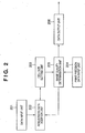
- Fig. 2 is a block diagram showing the arrangement of a data processing unit 102 according to the first embodiment
- Fig. 3 is a flowchart showing the processing for printing code data to be explained in the first embodiment
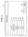
- Fig. 4 shows an example of a window that allows the user to select a source of code data
- Fig. 5 shows an example of a lookup table used to designate an error correction code size
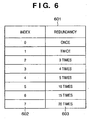
- Fig. 6 shows an example of a lookup table used to designate a redundancy
- Fig. 7 shows an example of the second code data embedding processing
- Fig. 8 shows an example of a window that allows the user to set the robustness and quality
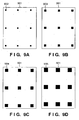
- Figs. 9A to 9D show examples of evaluation patterns used to measure the print precision
- Fig. 10 is a flowchart showing an example of the processing for determining the print precision
- Figs. 11A and 11B show examples of mask patterns used for dot detection
- Fig. 12 shows an example of a dot definition table
- Fig. 13 is a flowchart showing the processing for printing code data to be described in the second embodiment.
- Fig. 14 is a block diagram showing an image processing apparatus according to the second embodiment.
- This embodiment will explain a printing device which determines image quality based on its print characteristics, and can generate code data optimal to a print medium and, more particularly, a copying machine having a plurality of functions.
- Fig. 1 shows a printing device according to the present invention.
- a printing device 1 comprises the following processing units.
- Reference numeral 100 denotes an image input unit such as a scanner or the like.
- Reference numeral 101 denotes a configuration control unit such as a user interface (UI) panel and the like.
- Reference numeral 102 denotes a data processing unit such as a video controller and the like.
- Reference numeral 103 denotes a storage unit such as a hard disk (HD) and the like.
- Reference numeral 104 denotes an image transmission/reception unit such as a network interface (I/F) boar, FAX, and the like; and 105, an image output unit such as a printer and the like.
- I/F network interface
- FAX FAX
- This embodiment will explain an embodiment using a copying machine which is connected to a host computer 116, and comprises a printer and scanner to integrate a copy function, FAX function, and the like. However, the present invention is not limited to such specific embodiment.
- the data processing unit 102 comprises the following processors.
- Reference numeral 110 denotes an input unit I/F; 111, a control unit I/F; 112, an output unit I/F; 113, a transmission/reception unit I/F; and 114, a storage unit I/F.
- Reference numeral 106 denotes a program ROM which stores data processing and control programs.
- Reference numeral 107 denotes a data ROM; 108, a CPU; 109, a RAM serving as a main memory; and 115, a timer (timepiece function).
- the above processors are interconnected via an internal bus 117.
- the data processing unit 102 fetches image data by scanning an input image using the image input unit 100, or by receiving image data, which is sent from an external host computer or external FAX or via a network, via the image transmission/reception unit 104.
- the image data fetched by the data processing unit 102 undergoes image processing in accordance with an operation configuration set by the image input unit 100 or operation configuration data included in the externally transmitted image data. After that, upon printing the image data that has undergone the image processing by the printing device, that image data is output to the image output unit 105. Upon transmitting print data to the external network, the image data is output to the data transmission/reception unit 104. Upon storing the image data in the printing device, the image data is output to the storage unit 103.
- data in the data ROM 107 and the like are referred to as needed.
- a program is read out from the program ROM 106 in accordance with the processing operation configuration acquired via the control unit I/F 111, and image processing is executed using the RAM 109, storage unit 103, and the like.
- Fig. 2 is a block diagram showing the arrangement of this embodiment.
- a data input unit 201 inputs embedding data to be embedded in an image, and converts the input embedding data into code data.
- a robustness data addition unit 202 receives the code information, adds robustness information to the input code data, and generates and adds the code data added with the robustness data a predetermined number of times.
- a cell size setting unit 203 decides a cell size based on the code size of the code data added with the robustness data by the robustness data addition unit 202, and the area of a print medium where an image is to be printed.
- a print precision data input unit 204 receives print precision data recorded in the storage unit 103.
- An image quality determination unit 205 determines the quality of an image based on the density of dots in the cell size set by the cell size setting unit 203 and the print precision data input to the print precision data input unit 204.
- the robustness data addition unit 202 controls the size of the robustness data in accordance with the determination result of the image quality by the image quality determination unit 205.
- a data output unit 206 outputs the code data as print data.
- Step S301 Data to be coded is input.
- the data to be coded is input from the configuration control unit 101 or a dedicated application, printer driver (not shown), or the like on the host computer 116 connected to the printing device 1 based on an instruction from the user or an administrator of the printing device.
- data such as text or the like may be directly input or the location of data to be coded may be designated, and that data may be downloaded from the designated location to the application or printing device.
- meta data such as the user ID, print date & time, print job ID, and the like may be input and coded. Note that not only the user or the administrator of the printing device designates the data but also data (user ID, print date & time, print job ID, and the like) held inside the printing device may be automatically designated as data to be coded.
- Fig. 4 shows an example of a window that allows the user to select data to be input from the printing device main body.
- the selection window allows the user to select displayed items via the configuration control unit 101.
- Reference numeral 401 denotes a key input item that allows the user to directly input data to be coded.
- Reference numeral 402 denotes a BOX designation item that allows the user to select data pre-stored in the storage unit 103.
- Reference numeral 403 denotes a group ID designation item that allows the user to designate a management group of the operator.
- Reference numeral 404 denotes a body ID item that allows the user to designate the body number of the main body.
- Reference numeral 405 denotes a date designation item that allows the user to designate an output date.
- Reference numeral 406 denotes a user ID designation item that allows the user to designate an ID that specifies an output user.
- Reference numeral 407 denotes an OK key used to settle settings; and 408, a cancel key used
- Step S302 The data input or designated in step S301 is converted into code data. Initially, the data input unit 201 analyzes a data sequence input or designated in step S301. Then, the input data sequence is converted into a predetermined bit sequence, and a specifier that specifies a mode (numeric characters, alphanumeric characters, 8-bit byte, kanji, and the like) and a terminal pattern are added to the data as needed. That data is then converted into a predetermined bit code. Finally, in step S302 code data with a code size S (bits) is generated. Note that the code conversion method is not specified, and data is converted into code data after consistency with a decoding algorithm is ensured. Note that the code data may undergo arithmetic processing such as encryption and the like.
- Step S303 An error correction code is added to the code data as robustness data that enhances the robustness of the code data.
- Fig. 5 shows a lookup table 501 which is held in the storage unit 103 of the printing device 1 and is used to determine an error correction code size.
- a column 502 indicates an index used to designate the error correction code size, and a column 503 indicates the ratio of the corresponding error correction code size (the ratio of the error correction code size to the code size S).
- the error correction code size is decided by the numerical value in Fig. 5 .
- the user or administrator may change or create the lookup table 501 directly or via the network.
- code data with a code size N (bits) is generated by adding an error correction code to the code data converted in step S302.
- N S + X where X: the code size (bits) increased by the error correction code size.
- a BCH code premised on the 2D code a Reed-Solomon code compatible to a multi-dimensional code, an LDPC (low-density parity check code) code, or the like is used.
- LDPC low-density parity check code
- Step S304 A redundancy A is added to the code data with the code size N generated in step S303 as robustness data that can further enhance the robustness.
- Fig. 6 shows a lookup table 601 used to decide the redundancy.
- a column 602 indicates an index used to designate a redundancy, and a column 603 indicates a corresponding redundancy count.
- the redundancy A is decided by the numerical value in Fig. 6 .
- the user or administrator may change or create the lookup table 601 directly or via the network.
- Step S306 A cell size in which the code data is to be embedded is decided based on the code size M decided in step S305.
- the cell size is defined by dividing a document area where the code data is to be embedded in accordance with the code size M, and one or a plurality of bits of the code size M can be embedded for each cell size.
- the present invention expresses the code data as a set of dots.
- each cell may express code data (one cell expresses "1" or "0") or one cell may a plurality of bits.
- one cell expresses 1 bit. For example, when one cell expresses 1 bit, for example, if a dot is located above the center of a cell, it represents "1"; if a dot is located below the center of the cell, it represents "0".
- the minimum required number of cells is M.
- a cell 704 in Fig. 7 is an example added with one dot size 702, and a cell 705 is an example added with two dot sizes 702.
- Fig. 7 the full area of a document size 703 is divided into cell sizes. However, only a partial area of the document size may be divided into cell sizes in accordance with the data size to be embedded.
- Step S307 Image quality is calculated based on the cell size decided in step S306 and the number of pixels that expresses one dot to be described later.
- a dot size of 3 ⁇ 3 pixels is determined as that which can definitely be reproduced by the output device with reference to a dot definition table (to be described later) that describes print precision data generated by print precision determination processing to be described later.
- dot sizes 702 having 3 ⁇ 3 pixels as a minimum unit replace the dot size to be expressed in a cell, thereby calculating the maximum number Y of pixels of a dot.
- the dot size determined by the print precision determination processing is 3 ⁇ 3 pixels, and data is expressed by one or two dots per cell, the value of Y is 18.
- step S308 if the maximum number of pixels of a dot in a cell exceeds the image size P ⁇ Q of the cell, since the code data cannot be printed, it is determined in step S308 that the image quality is not satisfied.
- Step S308 Qu calculated in step S307 is assessed using: Qu ⁇ ⁇ ⁇ 1 : High ⁇ ⁇ 1 ⁇ Qu ⁇ ⁇ ⁇ 2 : Mid ⁇ ⁇ 2 ⁇ Qu : Low
- the image quality Qu is decided by the ratio of a dot that occupies a cell, as given by equation (4).
- conditional formulas (5) to (7) by setting ⁇ 1 ⁇ ⁇ 2 ( ⁇ 1 and ⁇ 2 are equal to or larger than 0), if inequality (5) is met, the dot density that occupies the cell is low. Hence, in this state, it is determined that image quality is high. Conversely, if inequality (7) is met, the image quality may deteriorate, but the robustness to an output print material may become higher than the case in which inequality (5) or (6) is met. Hence, in this state, it is determined that robustness is high.
- the values of ⁇ 1 and ⁇ 2 may be arbitrarily determined in accordance with the characteristics of the printing device.
- Conditional formulas (5) to (7) link with a window used to set the robustness/quality shown in Fig. 8.
- Fig. 8 allows the user to select the robustness and image quality in three levels: "robustness priority" level 801, "image quality priority” level 803, and "middle priority” level 802. The user can also select the condition using the configuration control unit 101 in accordance with data of a document to be added.
- reference numeral 804 denotes an OK key used to settle the selected condition; and 805, a cancel key used to cancel the selected condition.
- the level 801 corresponds to inequality (7) that represents robustness priority.
- the level 803 corresponds to inequality (5) that sets the highest image quality.
- the level 802 corresponds to inequality (6) that sets an intermediate level. In this embodiment, assume that the level 802 is set as a default setting.
- step S308 If it is determined in step S308 that the image quality Qu is not satisfied, the lookup table 601 of the redundancy is looked up again.
- the index is set to be "5" as the default setting. However, upon resetting the redundancy, the index is set to be "4" as a setting lower by one level, thus adjusting the redundancy.
- step S309 If the image quality Qu is not satisfied, this processing is repeated until the index value in Fig. 5 indicates "0".
- the configuration control unit 101 notifies the operator that the code data cannot be embedded based on the designated robustness/quality setting.
- step S308 If the corresponding conditional formula is met in step S308, the process advances to step S309.
- Step S309 If the corresponding conditional formula is met in step S308, the code data is generated as print data, thus ending the processing.
- the generated code data is combined with image data from the scanner 100, PDL data from the host computer 116, and the like inside the data processing unit, and the combined data is output via the image output unit 105.
- the print precision determination processing is executed independently from the code data generation processing.
- the print precision is determined using the minimum dot size that the printing device can print as a print criterion.
- the user or administrator launches the print precision determination processing periodically or at an arbitrary timing, and the processing result is stored in the printing device 1.
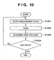
- Fig. 10 is a flowchart showing the processing for deciding the print precision.
- Step S1001 Measurement patches (images) are output.
- four patterns shown in Figs. 9A to 9D are output as measurement patches. Each pattern is obtained by printing data of an identical dot size at nine points of an output paper size.
- Reference numeral 901 denotes a paper size to be output; 902 ( Fig. 9A ), a 1 ⁇ 1 dot size; 903 ( Fig. 9B ), a 2 ⁇ 2 dot size; 904 ( Fig. 9C ), a 3 ⁇ 3 dot size; and 905 ( Fig. 9D ), a 4 ⁇ 4 dot size.
- step S1001 a pattern generation program stored in the storage unit 103 is launched, and the CPU 108 assures a predetermined memory area on the RAM 109. After measurement patch data in Fig. 9A is generated, the generated image data is output to and printed by the image output unit 105.
- the measurement patches to be output are not limited to black ones.
- a plurality of color patches may be generated and output.
- Step S1002 The image input unit 100 scans the measurement patches output in step S1001.
- the scanned patch images are temporarily stored in the RAM 109 as patch image data via the input unit I/F 110.
- each patch image data is separated into signals of three channels red, green, and blue, and are fetched as multi-valued data.
- each patch image data is scanned as a gray signal and is fetched as multi-valued data.
- Step S1003 It is checked if a detectable dot is printed in the patch image data stored in step S1002.
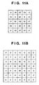
- the print precision is determined by the convolution operation between mask patterns shown in Figs. 11A and 11B and the patch image data temporarily stored in the RAM 109 in step S1002.
- the mask patterns shown in Figs. 11A and 11B have different sizes and coefficients depending on the sizes of patch image data to be determined.
- Fig. 11A is used for the patch image data obtained by scanning the measurement patches shown in Figs. 9A and 9B
- Fig. 11B is used for the patch image data obtained by scanning the measurement patches shown in Figs. 9C and 9D .
- These mask patterns are stored in advance in the storage unit 103.
- the CPU 108 stores the convolution operation results in the RAM 109.
- this embodiment adopts the processing for switching the threshold.
- Step S1004 It is confirmed if the last patch is processed. Steps S1001 to S1003 are repeated until the last patch is processed.
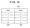
- Fig. 12 shows a dot definition table 1201 generated by this processing.
- a column 1202 indicates an index, which corresponds to each dot size to be confirmed.
- a column 1203 stores the result determined by this flow.
- a dot size whose column 1203 describes "1" and which corresponds to the smallest index is applied.
- the measurement patches are printed on a plurality of pages, and the printed patches are scanned.
- the measurement patches may be printed on one page together, and may be separately analyzed upon scanning.
- four different dot sizes are verified upon recognizing the characteristics of the output device.
- a plurality of more than four sizes may be used.
- the configuration control unit 101 notifies the user of the contents.
- the notification may be simply displayed on the configuration control unit 101.
- data may be sent to a driver (not shown) used in the host computer 116.
- that notification may be sent to a management server (not shown).
- the image quality of the code data can be determined in consideration of the changing print characteristics. Also, the code data can be generated in consideration of the changing print characteristics.
- the number of conditions that represent the robustness/quality is not limited to three, and a larger number of conditions may be used to allow flexible determination.
- This embodiment will explain processing for changing not only the redundancy but also the error correction code size, as shown in Fig. 13 .
- the same reference numerals denote the same components as in the first embodiment, and a repetitive description thereof will be avoided. Only differences will be described below.
- step S1301 the index of the lookup table 501 is confirmed. If it is determined in step S1302 that the image quality Qu is not satisfied, the error correction code size is set again in step S1301.
- the first embodiment has explained an embodiment of the present invention in an advanced-function printing device such as an MFP or the like.
- the present invention may be applied to a system configured by a plurality of devices (e.g., a host computer, interface device, scanner, printer, and the like).
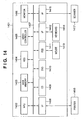
- Fig. 14 is a block diagram for explaining the arrangement of an image processing system according to this embodiment. Note that use of all the functions shown in Fig. 14 is not indispensable to implement the image processing apparatus.
- a computer 1401 can be a generally prevalent personal computer, which can receive an image scanned by an image input device 1417 such as a scanner or the like, and can edit and store the received image. Also, the computer 1401 can print the image obtained by the image input device 1417 using a printer 1416. Note that the user inputs various instructions and the like via a mouse 1413 and keyboard 1414.
- an MPU 1402 controls the operations of respective blocks in the computer 1401, or can execute internally stored programs.
- a main memory 1403 is a device which temporarily stores programs and image data to be processed for the processing to be executed by the MPU 1402.
- a hard disk drive (HDD) 1404 is a device which stores programs and image data transferred to the main memory 1403 or the like in advance, and can save image data after processing.
- a scanner interface (I/F) 1415 is an I/F which is connected to the scanner 1417 that scans a document, film, or the like to generate image data, and can receive image data scanned by the scanner 1417.
- a printer I/F 1408 is an I/F which is connected to the printer 1416 that prints image data, and can transmit image data to be printed to the printer 1416.
- a CD drive 1409 is a device which can read out data stored in a CD (CD-R/CD-RW) as one of external storage media or write data on the CD.
- a floppy disk drive (FD) 1411 is a device which can read out data from an FD or can write data on the FD as in the CD drive 1409.
- a DVD drive 1410 is a device which can read out data from a DVD or can write data on the DVD as in the FDD 1411.
- the CD, FD, DVD, or the like store image edit programs or a printer driver, these programs are installed on the HDD 1404 and are transferred to the main memory 1403 as needed.
- An interface (I/F) 1412 is an I/F which is connected to the mouse 1413 and keyboard 1414 to accept input instructions from them.
- a monitor 1406 is a display device which can display the result and processes of watermark information extraction processing.
- a video controller 1405 is a device used to transmit display data to the monitor 1406.
- the image input unit 100 corresponds to the scanner 1417
- the configuration control unit 101 corresponds to the monitor 1406.
- the data processing unit 102 corresponds to the main memory 1403 and MPU 1402
- the storage unit 103 corresponds to the HDD 1404
- the image transmission/reception unit 104 corresponds to the I/Fs 1408 and 1415
- the image output unit 105 corresponds to the printer 1416.
- the present invention is not limited to the first to third embodiments, and allows various modifications as long as the same effects can be obtained.
- the error correction code and redundancy are added as robustness data.
- either one of these data may be added as the robustness data.
- the image quality is determined based on the data size of the code data added with the robustness data.
- the image quality may be determined based on only the code data without adding the robustness data.
- the processing for realizing the robustness/quality designated by the user is done by changing the error correction code size and redundancy.
- the image quality Qu is verified by updating only the error correction code size. If the image quality Qu is not satisfied yet, the redundancy may be updated.
- the image quality Qu is determined using conditional formulas (5) to (7).
- the present invention is not limited to this.
- the magnitude relationship between the image quality Qu and a certain threshold ⁇ ' may be used as a condition. For example, if the image quality Qu is larger than the threshold ⁇ ', generation and printing of code data are aborted.
- the configuration control unit 101 may display a message for the user indicating that code data cannot be generated.
- the present invention can be applied to an apparatus comprising a single device or to system constituted by a plurality of devices.
- the invention can be implemented by supplying a software program, which implements the functions of the foregoing embodiments, directly or indirectly to a system or apparatus, reading the supplied program code with a computer of the system or apparatus, and then executing the program code.
- a software program which implements the functions of the foregoing embodiments
- reading the supplied program code with a computer of the system or apparatus, and then executing the program code.
- the mode of implementation need not rely upon a program.
- the program code installed in the computer also implements the present invention.
- the claims of the present invention also cover a computer program for the purpose of implementing the functions of the present invention.
- the program may be executed in any form, such as an object code, a program executed by an interpreter, or scrip data supplied to an operating system.
- Example of storage media that can be used for supplying the program are a floppy disk, a hard disk, an optical disk, a magneto-optical disk, a CD-ROM, a CD-R, a CD-RW, a magnetic tape, a non-volatile type memory card, a ROM, and a DVD (DVD-ROM and a DVD-R).
- a client computer can be connected to a website on the Internet using a browser of the client computer, and the computer program of the present invention or an automatically-installable compressed file of the program can be downloaded to a recording medium such as a hard disk.
- the program of the present invention can be supplied by dividing the program code constituting the program into a plurality of files and downloading the files from different websites.
- a WWW World Wide Web
- a storage medium such as a CD-ROM
- an operating system or the like running on the computer may perform all or a part of the actual processing so that the functions of the foregoing embodiments can be implemented by this processing.
- a CPU or the like mounted on the function expansion board or function expansion unit performs all or a part of the actual processing so that the functions of the foregoing embodiments can be implemented by this processing.
Applications Claiming Priority (1)
| Application Number | Priority Date | Filing Date | Title |
|---|---|---|---|
| JP2006216916A JP4829715B2 (ja) | 2006-08-09 | 2006-08-09 | 画像処理装置、画像処理方法、画像処理プログラム並びに記憶媒体 |
Publications (2)
| Publication Number | Publication Date |
|---|---|
| EP1887778A1 EP1887778A1 (en) | 2008-02-13 |
| EP1887778B1 true EP1887778B1 (en) | 2011-04-06 |
Family
ID=38515835
Family Applications (1)
| Application Number | Title | Priority Date | Filing Date |
|---|---|---|---|
| EP07013124A Expired - Fee Related EP1887778B1 (en) | 2006-08-09 | 2007-07-04 | Apparatus and method of image quality control for printing of code data |
Country Status (5)
| Country | Link |
|---|---|
| US (1) | US8482805B2 (zh) |
| EP (1) | EP1887778B1 (zh) |
| JP (1) | JP4829715B2 (zh) |
| CN (1) | CN101123663B (zh) |
| DE (1) | DE602007013655D1 (zh) |
Families Citing this family (5)
| Publication number | Priority date | Publication date | Assignee | Title |
|---|---|---|---|---|
| JP2010074436A (ja) * | 2008-09-17 | 2010-04-02 | Ricoh Co Ltd | 画像処理装置、画像処理方法、画像処理プログラム |
| CN101895661B (zh) * | 2010-01-11 | 2016-01-27 | 珠海天威飞马打印耗材有限公司 | 耗材芯片、耗材容器、成像装置及其成像控制方法 |
| JP7010016B2 (ja) * | 2018-01-19 | 2022-01-26 | セイコーエプソン株式会社 | コード変換装置、出力物の生産方法およびコード変換プログラム |
| WO2020190278A1 (en) * | 2019-03-19 | 2020-09-24 | Hewlett-Packard Development Company, L.P. | Extraction and comparison of actual and target surface attribute values |
| US20230034244A1 (en) * | 2019-11-28 | 2023-02-02 | Advanced Track & Trace | Secure marking method and device and authentication method and device |
Family Cites Families (12)
| Publication number | Priority date | Publication date | Assignee | Title |
|---|---|---|---|---|
| JP3010136B2 (ja) * | 1996-03-28 | 2000-02-14 | オリンパス光学工業株式会社 | コードデータ出力装置 |
| JP3053576B2 (ja) * | 1996-08-07 | 2000-06-19 | オリンパス光学工業株式会社 | コードイメージデータ出力装置及び出力方法 |
| JP3745179B2 (ja) * | 1999-01-12 | 2006-02-15 | キヤノン株式会社 | 情報処理装置及びその制御方法及び記憶媒体 |
| CN1169342C (zh) * | 1999-06-07 | 2004-09-29 | 惠普公司 | 自动确定打印装置介质盘中介质类型的系统和有关方法 |
| JP3736379B2 (ja) * | 2001-04-19 | 2006-01-18 | ソニー株式会社 | 電子透かし埋め込み処理装置、電子透かし検出処理装置、および電子透かし埋め込み処理方法、電子透かし検出処理方法、並びにプログラム記憶媒体、およびプログラム |
| JP3628312B2 (ja) | 2001-07-18 | 2005-03-09 | 沖電気工業株式会社 | 透かし情報埋め込み装置,及び,透かし情報検出装置 |
| US7085399B2 (en) * | 2002-06-18 | 2006-08-01 | Oki Electric Industry Co., Ltd. | Watermark information embedding device and watermark information detection device |
| JP2004104494A (ja) * | 2002-09-10 | 2004-04-02 | Canon Inc | 電子透かし埋め込み装置及びその制御方法 |
| JP3975870B2 (ja) | 2002-09-10 | 2007-09-12 | コニカミノルタビジネステクノロジーズ株式会社 | 画像データ配信システム |
| JP2005286999A (ja) * | 2004-03-05 | 2005-10-13 | Fuji Photo Film Co Ltd | 閾値マトリクスの割当方法 |
| JP4155213B2 (ja) * | 2004-03-10 | 2008-09-24 | 沖電気工業株式会社 | 電子透かし埋め込み装置,電子透かし検出装置,電子透かし埋め込み方法,および電子透かし検出方法 |
| JP3930502B2 (ja) * | 2004-03-29 | 2007-06-13 | 沖電気工業株式会社 | 品質調整システムおよび透かし品質検査装置 |
-
2006
- 2006-08-09 JP JP2006216916A patent/JP4829715B2/ja not_active Expired - Fee Related
-
2007
- 2007-07-04 EP EP07013124A patent/EP1887778B1/en not_active Expired - Fee Related
- 2007-07-04 DE DE602007013655T patent/DE602007013655D1/de active Active
- 2007-07-12 US US11/776,806 patent/US8482805B2/en not_active Expired - Fee Related
- 2007-08-09 CN CN200710142925XA patent/CN101123663B/zh not_active Expired - Fee Related
Also Published As
| Publication number | Publication date |
|---|---|
| JP2008042733A (ja) | 2008-02-21 |
| US8482805B2 (en) | 2013-07-09 |
| CN101123663A (zh) | 2008-02-13 |
| EP1887778A1 (en) | 2008-02-13 |
| CN101123663B (zh) | 2011-01-05 |
| DE602007013655D1 (de) | 2011-05-19 |
| JP4829715B2 (ja) | 2011-12-07 |
| US20080037037A1 (en) | 2008-02-14 |
Similar Documents
| Publication | Publication Date | Title |
|---|---|---|
| US8625167B2 (en) | Image processing, reading or forming apparatus and method for adding specific image data to obtained image data while encrypting details data specifying specific data and adding encrypted details data to obtained image data, and non-transitory recording medium recording program for causing computer to function as the same | |
| US8508792B2 (en) | Image processing apparatus, an image processing method, and a program thereof for handling a copy-forgery-inhibited pattern image | |
| KR100805594B1 (ko) | 농도 결정 방법, 화상 형성 장치 및 화상 처리 시스템 | |
| US20110002012A1 (en) | Image processing apparatus, image reading apparatus, image forming apparatus and recording medium | |
| US8442336B2 (en) | Image processing apparatus, compression method, and extension method | |
| EP1887778B1 (en) | Apparatus and method of image quality control for printing of code data | |
| JP5212886B2 (ja) | 画像形成システム、及び、画像形成プログラム | |
| JP2010028309A (ja) | 装置、方法、プログラムおよび記憶媒体 | |
| US7911649B2 (en) | Image outputting apparatus and control method thereof with output of color copy despite setting for black and white copy | |
| US7460158B2 (en) | Recording material consumption control for an image forming apparatus | |
| JP4208901B2 (ja) | 情報処理装置、画像処理装置、それらの装置の制御方法、プログラム、及びコンピュータ可読の記憶媒体 | |
| CN101090433A (zh) | 图像形成装置和图像形成方法 | |
| US7952750B2 (en) | Image processing apparatus and image processing method | |
| JP4653006B2 (ja) | 潜像画像、背景画像の濃度信号値を決定する方法及び装置及びプログラム | |
| JP4323742B2 (ja) | 画像処理装置および画像処理装置の制御方法およびプログラム | |
| JP4979428B2 (ja) | 画像処理装置およびその制御方法 | |
| JP2007258804A (ja) | 画像処理装置 | |
| JP2007158808A (ja) | 画像処理装置、その装置の制御方法、プログラム、記憶媒体 | |
| JP2007166510A (ja) | 画像処理装置、画像処理装置の制御方法、プログラム、及び記憶媒体 | |
| JP2007088968A (ja) | 出力システム | |
| JP2009194538A (ja) | 二次元コードを処理する装置、方法、プログラム、記憶媒体 | |
| US8170353B2 (en) | Information processing apparatus and control method thereof | |
| JP2010171598A (ja) | 画像処理装置 | |
| JP2004255820A (ja) | 画像形成装置及びその方法 | |
| JP2006174241A (ja) | 画像形成装置及びその制御方法 |
Legal Events
| Date | Code | Title | Description |
|---|---|---|---|
| PUAI | Public reference made under article 153(3) epc to a published international application that has entered the european phase |
Free format text: ORIGINAL CODE: 0009012 |
|
| AK | Designated contracting states |
Kind code of ref document: A1 Designated state(s): AT BE BG CH CY CZ DE DK EE ES FI FR GB GR HU IE IS IT LI LT LU LV MC MT NL PL PT RO SE SI SK TR |
|
| AX | Request for extension of the european patent |
Extension state: AL BA HR MK YU |
|
| 17P | Request for examination filed |
Effective date: 20080813 |
|
| AKX | Designation fees paid |
Designated state(s): DE FR GB |
|
| 17Q | First examination report despatched |
Effective date: 20081015 |
|
| GRAP | Despatch of communication of intention to grant a patent |
Free format text: ORIGINAL CODE: EPIDOSNIGR1 |
|
| GRAS | Grant fee paid |
Free format text: ORIGINAL CODE: EPIDOSNIGR3 |
|
| GRAA | (expected) grant |
Free format text: ORIGINAL CODE: 0009210 |
|
| AK | Designated contracting states |
Kind code of ref document: B1 Designated state(s): DE FR GB |
|
| REG | Reference to a national code |
Ref country code: GB Ref legal event code: FG4D |
|
| REF | Corresponds to: |
Ref document number: 602007013655 Country of ref document: DE Date of ref document: 20110519 Kind code of ref document: P |
|
| REG | Reference to a national code |
Ref country code: DE Ref legal event code: R096 Ref document number: 602007013655 Country of ref document: DE Effective date: 20110519 |
|
| PLBE | No opposition filed within time limit |
Free format text: ORIGINAL CODE: 0009261 |
|
| STAA | Information on the status of an ep patent application or granted ep patent |
Free format text: STATUS: NO OPPOSITION FILED WITHIN TIME LIMIT |
|
| 26N | No opposition filed |
Effective date: 20120110 |
|
| REG | Reference to a national code |
Ref country code: DE Ref legal event code: R097 Ref document number: 602007013655 Country of ref document: DE Effective date: 20120110 |
|
| REG | Reference to a national code |
Ref country code: FR Ref legal event code: PLFP Year of fee payment: 10 |
|
| PGFP | Annual fee paid to national office [announced via postgrant information from national office to epo] |
Ref country code: GB Payment date: 20160727 Year of fee payment: 10 Ref country code: DE Payment date: 20160731 Year of fee payment: 10 |
|
| PGFP | Annual fee paid to national office [announced via postgrant information from national office to epo] |
Ref country code: FR Payment date: 20160726 Year of fee payment: 10 |
|
| REG | Reference to a national code |
Ref country code: DE Ref legal event code: R119 Ref document number: 602007013655 Country of ref document: DE |
|
| GBPC | Gb: european patent ceased through non-payment of renewal fee |
Effective date: 20170704 |
|
| REG | Reference to a national code |
Ref country code: FR Ref legal event code: ST Effective date: 20180330 |
|
| PG25 | Lapsed in a contracting state [announced via postgrant information from national office to epo] |
Ref country code: GB Free format text: LAPSE BECAUSE OF NON-PAYMENT OF DUE FEES Effective date: 20170704 Ref country code: DE Free format text: LAPSE BECAUSE OF NON-PAYMENT OF DUE FEES Effective date: 20180201 |
|
| PG25 | Lapsed in a contracting state [announced via postgrant information from national office to epo] |
Ref country code: FR Free format text: LAPSE BECAUSE OF NON-PAYMENT OF DUE FEES Effective date: 20170731 |